GROUND DISTRIBUTION NISSAN ALMERA N16 2001 Electronic Repair Manual
[x] Cancel search | Manufacturer: NISSAN, Model Year: 2001, Model line: ALMERA N16, Model: NISSAN ALMERA N16 2001Pages: 2493, PDF Size: 66.97 MB
Page 17 of 2493
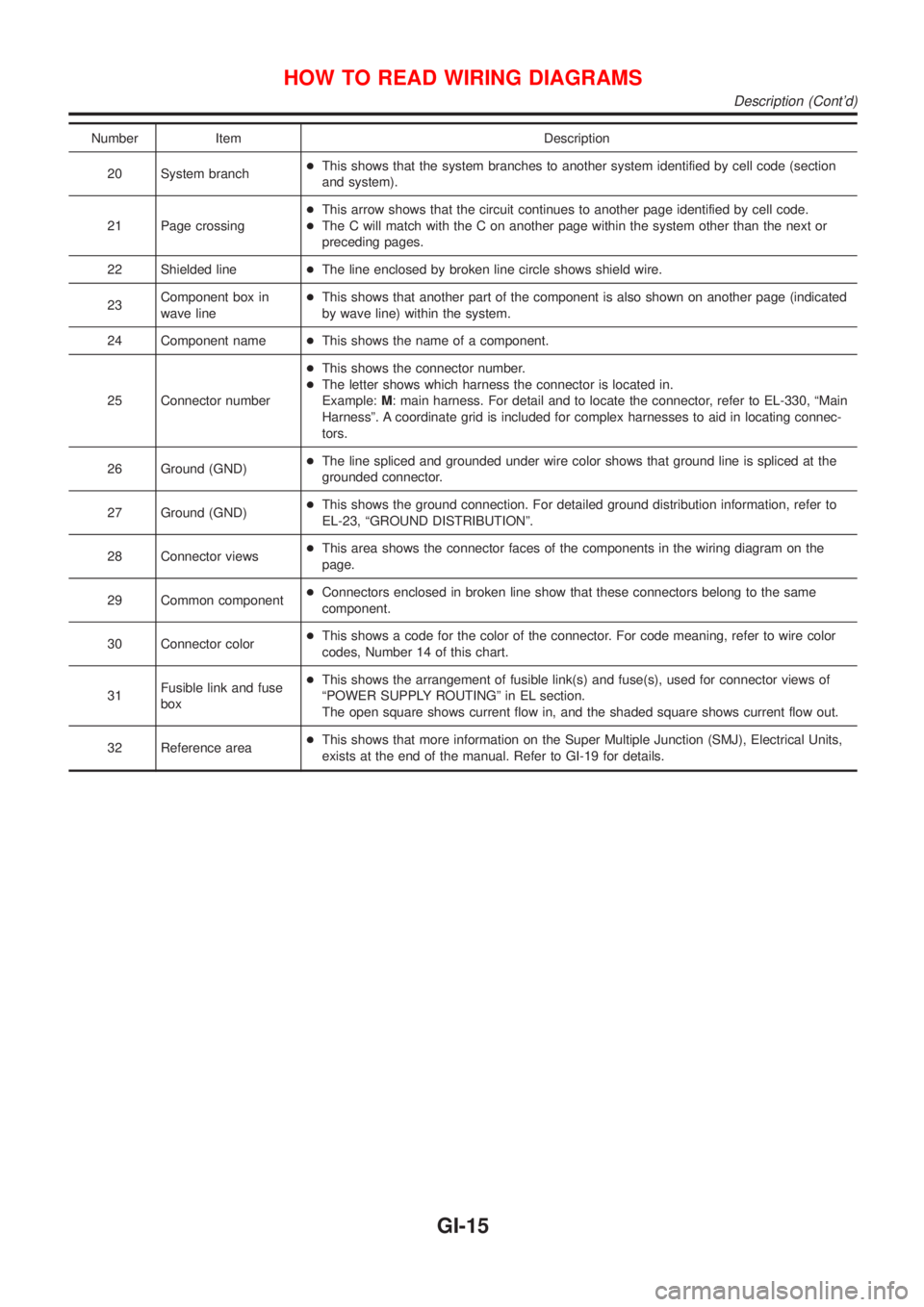
Number Item Description
20 System branch+This shows that the system branches to another system identified by cell code (section
and system).
21 Page crossing+This arrow shows that the circuit continues to another page identified by cell code.
+The C will match with the C on another page within the system other than the next or
preceding pages.
22 Shielded line+The line enclosed by broken line circle shows shield wire.
23Component box in
wave line+This shows that another part of the component is also shown on another page (indicated
by wave line) within the system.
24 Component name+This shows the name of a component.
25 Connector number+This shows the connector number.
+The letter shows which harness the connector is located in.
Example:M: main harness. For detail and to locate the connector, refer to EL-330, ªMain
Harnessº. A coordinate grid is included for complex harnesses to aid in locating connec-
tors.
26 Ground (GND)+The line spliced and grounded under wire color shows that ground line is spliced at the
grounded connector.
27 Ground (GND)+This shows the ground connection. For detailed ground distribution information, refer to
EL-23, ªGROUND DISTRIBUTIONº.
28 Connector views+This area shows the connector faces of the components in the wiring diagram on the
page.
29 Common component+Connectors enclosed in broken line show that these connectors belong to the same
component.
30 Connector color+This shows a code for the color of the connector. For code meaning, refer to wire color
codes, Number 14 of this chart.
31Fusible link and fuse
box+This shows the arrangement of fusible link(s) and fuse(s), used for connector views of
ªPOWER SUPPLY ROUTINGº in EL section.
The open square shows current flow in, and the shaded square shows current flow out.
32 Reference area+This shows that more information on the Super Multiple Junction (SMJ), Electrical Units,
exists at the end of the manual. Refer to GI-19 for details.
HOW TO READ WIRING DIAGRAMS
Description (Cont'd)
GI-15
Page 315 of 2493
SEF605X
+Do not operate fuel pump when there is no fuel in lines.
+Tighten fuel hose clamps to the specified torque.
SEF709Y
+Do not depress accelerator pedal when starting.
+Immediately after starting, do not rev up engine unneces-
sarily.
+Do not rev up engine just prior to shutdown.
SEF708Y
+When installing C.B. ham radio or a mobile phone, be sure
to observe the following as it may adversely affect elec-
tronic control systems depending on installation location.
1)Keep the antenna as far as possible from the electronic
control units.
2)Keep the antenna feeder line more than 20 cm (8 in) away
from the harness of electronic controls.
Do not let them run parallel for a long distance.
3)Adjust the antenna and feeder line so that the standing-
wave ratio can be kept smaller.
4)Be sure to ground the radio to vehicle body.
Wiring Diagrams and Trouble DiagnosisNJEC0006When you read Wiring diagrams, refer to the following:
+GI-12, ªHOW TO READ WIRING DIAGRAMSº
+EL-10, ªPOWER SUPPLY ROUTINGº for power distribution
circuit
When you perform trouble diagnosis, refer to the following:
+GI-31, ªHOW TO FOLLOW TEST GROUP IN TROUBLE
DIAGNOSISº
+GI-21, ªHOW TO PERFORM EFFICIENT DIAGNOSIS FOR
AN ELECTRICAL INCIDENTº
PRECAUTIONSQG
Engine Fuel & Emission Control System (Cont'd)
EC-19
Page 793 of 2493
SEF348N
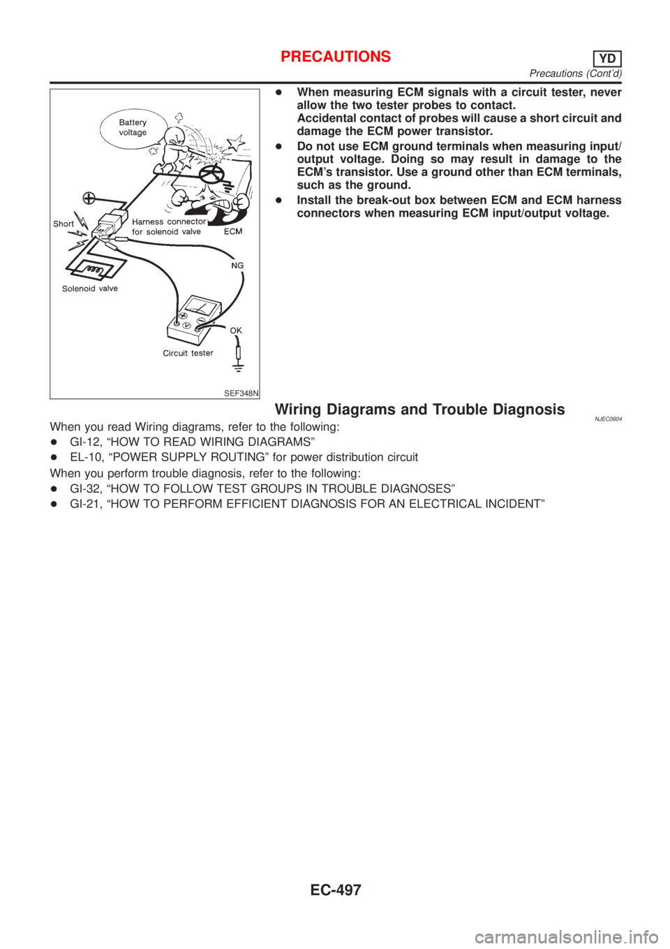
+When measuring ECM signals with a circuit tester, never
allow the two tester probes to contact.
Accidental contact of probes will cause a short circuit and
damage the ECM power transistor.
+Do not use ECM ground terminals when measuring input/
output voltage. Doing so may result in damage to the
ECM's transistor. Use a ground other than ECM terminals,
such as the ground.
+Install the break-out box between ECM and ECM harness
connectors when measuring ECM input/output voltage.
Wiring Diagrams and Trouble DiagnosisNJEC0604When you read Wiring diagrams, refer to the following:
+GI-12, ªHOW TO READ WIRING DIAGRAMSº
+EL-10, ªPOWER SUPPLY ROUTINGº for power distribution circuit
When you perform trouble diagnosis, refer to the following:
+GI-32, ªHOW TO FOLLOW TEST GROUPS IN TROUBLE DIAGNOSESº
+GI-21, ªHOW TO PERFORM EFFICIENT DIAGNOSIS FOR AN ELECTRICAL INCIDENTº
PRECAUTIONSYD
Precautions (Cont'd)
EC-497
Page 2113 of 2493
ELECTRICAL SYSTEM
SECTION
EL
CONTENTS
PRECAUTIONS...............................................................4
Supplemental Restraint System (SRS)²AIR
BAG²and²SEAT BELT PRE-TENSIONER²...............4
Wiring Diagrams and Trouble Diagnosis .....................4
HARNESS CONNECTOR................................................5
Description ...................................................................5
STANDARDIZED RELAY................................................7
Description ...................................................................7
POWER SUPPLY ROUTING...........................................9
Schematic ..................................................................10
Wiring Diagram - POWER - ......................................12
Inspection...................................................................22
GROUND........................................................................23
Ground Distribution ....................................................23
COMBINATION SWITCH..............................................37
Check .........................................................................37
Replacement ..............................................................38
STEERING SWITCH......................................................39
Check .........................................................................39
HEADLAMP...................................................................40
Wiring Diagram - H/LAMP -.......................................40
Trouble Diagnoses.....................................................41
Bulb Replacement .....................................................42
Aiming Adjustment .....................................................42
HEADLAMP - DAYTIME LIGHT SYSTEM -.................44
System Description ....................................................44
Schematic ..................................................................45
Wiring Diagram - DTRL - ...........................................46
Trouble Diagnoses.....................................................49
Bulb Replacement .....................................................49
Aiming Adjustment .....................................................50
HEADLAMP - HEADLAMP AIMING CONTROL -........51
Wiring Diagram - H/AIM - ..........................................51
PARKING, LICENSE AND TAIL LAMPS.....................53
Wiring Diagram - TAIL/L - ..........................................53
STOP LAMP..................................................................56
Wiring Diagram - STOP/L - .......................................56
BACK-UP LAMP............................................................58
Wiring Diagram - BACK/L - .......................................58FRONT FOG LAMP.......................................................60
Wiring Diagram - F/FOG - .........................................60
Bulb Replacement .....................................................61
Aiming Adjustment .....................................................62
REAR FOG LAMP.........................................................63
Wiring Diagram - R/FOG -.........................................63
TURN SIGNAL AND HAZARD WARNING LAMPS.....65
System Description ....................................................65
Schematic ..................................................................66
Wiring Diagram - TURN - ..........................................67
Trouble Diagnoses.....................................................70
ILLUMINATION..............................................................71
Schematic ..................................................................71
Wiring Diagram - ILL - ...............................................72
INTERIOR ROOM LAMP...............................................76
System Description/ With Interior Room Lamp
Timer ..........................................................................76
Wiring Diagram - ROOM/L -/ With Interior Room
Lamp Timer ................................................................78
Trouble Diagnoses/ With Interior Room Lamp
Timer ..........................................................................80
Wiring Diagram - ROOM/L -/ Without Timer .............86
SPOT AND TRUNK ROOM LAMPS.............................87
Wiring Diagram - INT/L - ...........................................87
METERS AND GAUGES...............................................89
Component Parts and Harness Connector
Location .....................................................................89
System Description ....................................................89
Combination Meter ....................................................91
Schematic ..................................................................92
Construction ...............................................................93
Wiring Diagram - METER - .......................................94
Combination Meter Self-Diagnosis ............................96
Trouble Diagnoses.....................................................99
Electrical Components Inspection ...........................106
WARNING LAMPS......................................................107
Schematic ................................................................107
Wiring Diagram - WARN - .......................................108
Electrical Components Inspection ........................... 112
Page 2135 of 2493
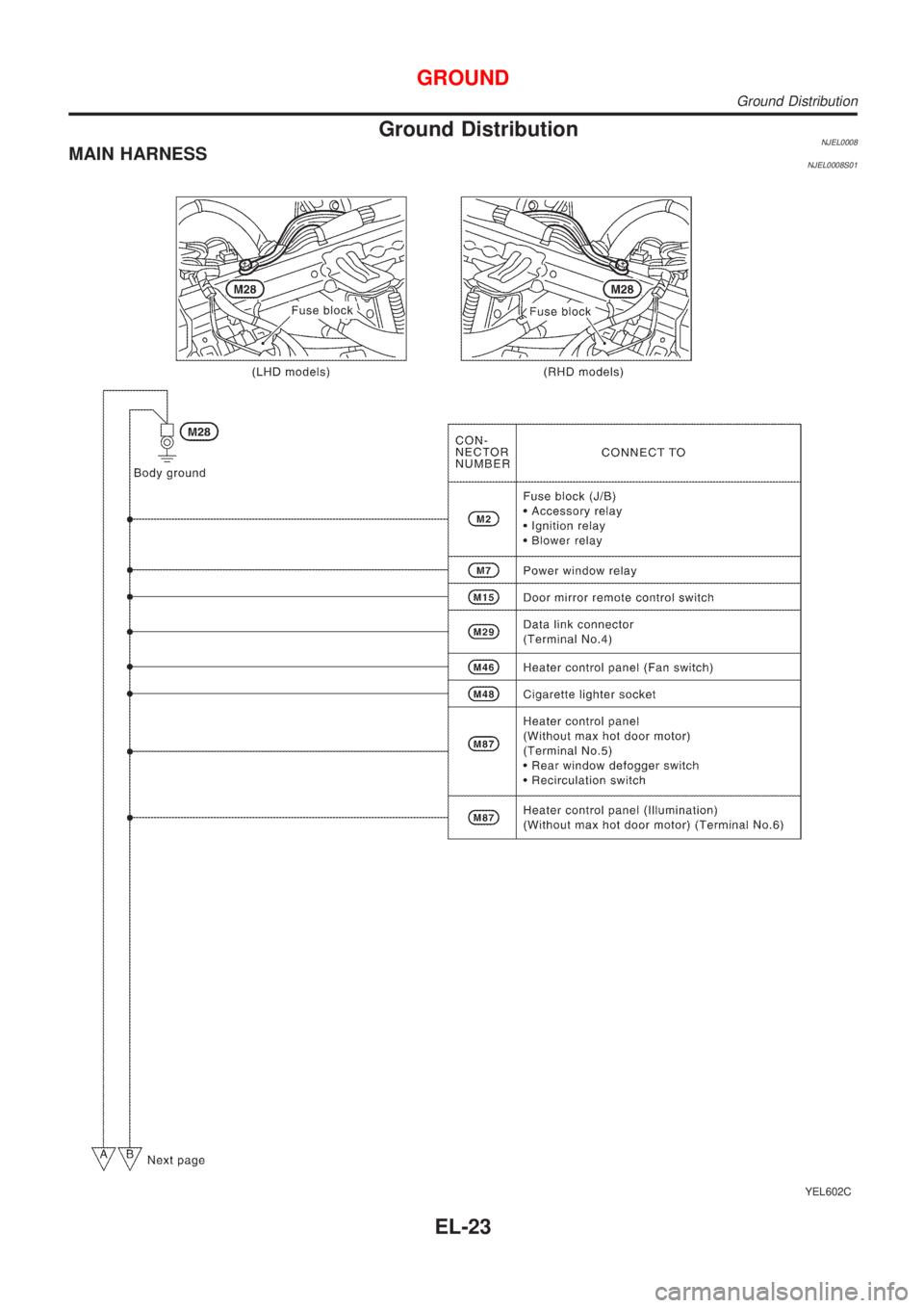
Ground DistributionNJEL0008MAIN HARNESSNJEL0008S01
YEL602C
GROUND
Ground Distribution
EL-23
Page 2136 of 2493
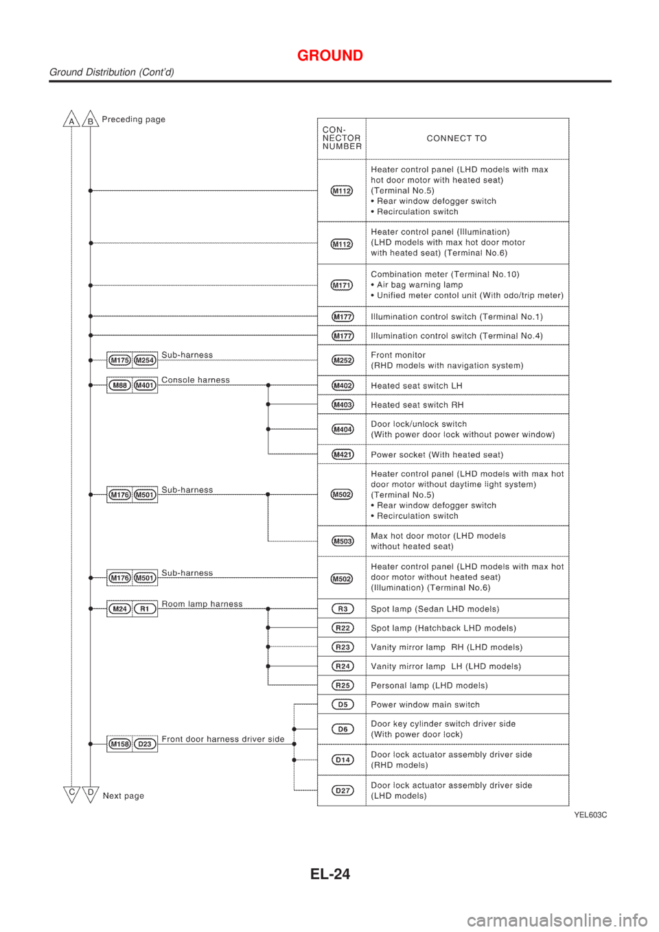
YEL603C
GROUND
Ground Distribution (Cont'd)
EL-24
Page 2137 of 2493
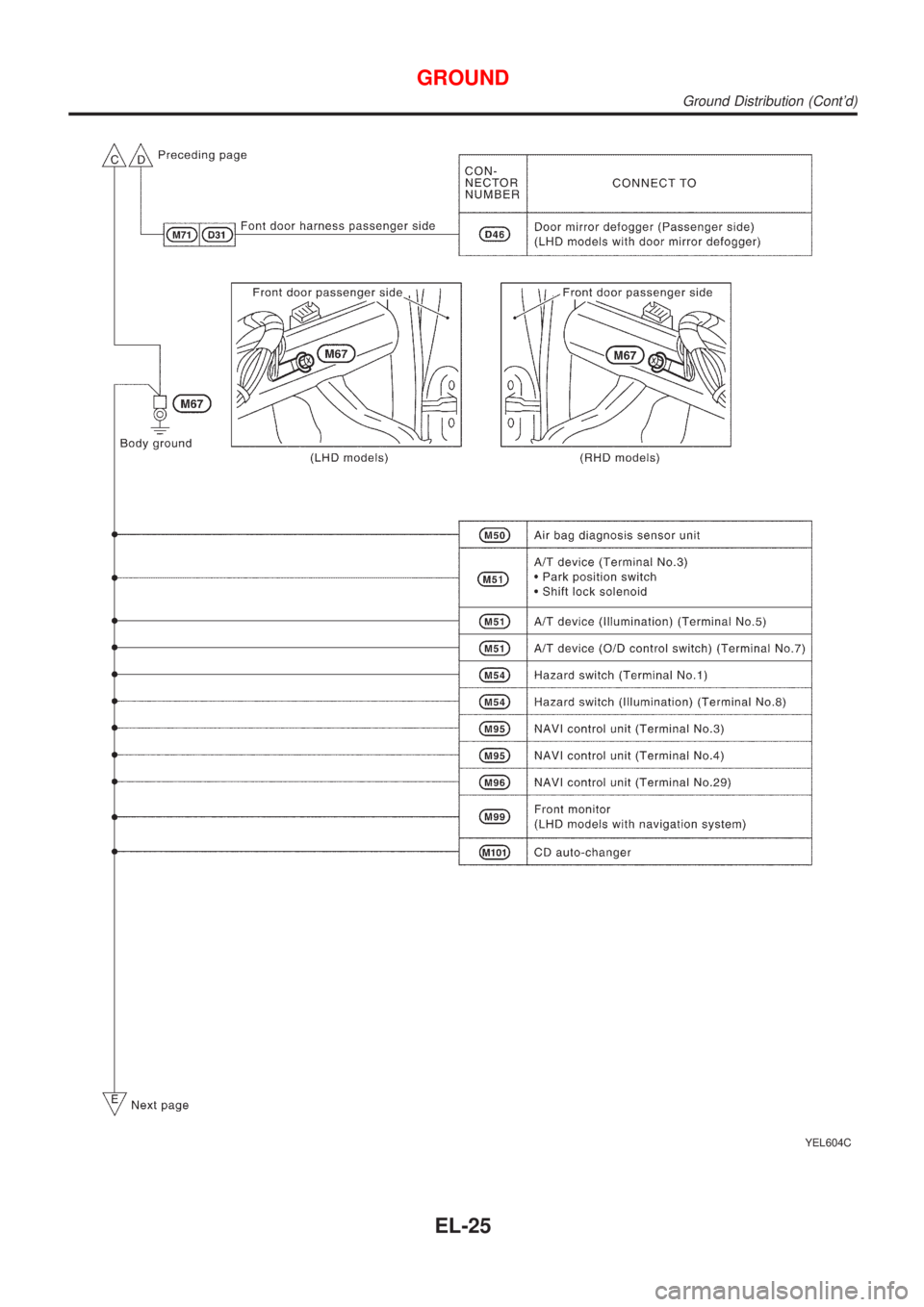
YEL604C
GROUND
Ground Distribution (Cont'd)
EL-25
Page 2138 of 2493
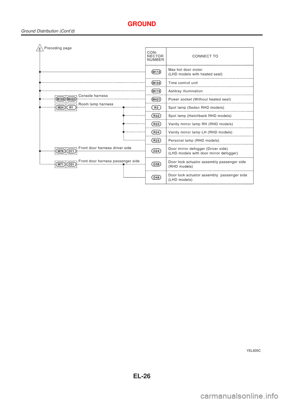
YEL605C
GROUND
Ground Distribution (Cont'd)
EL-26
Page 2139 of 2493
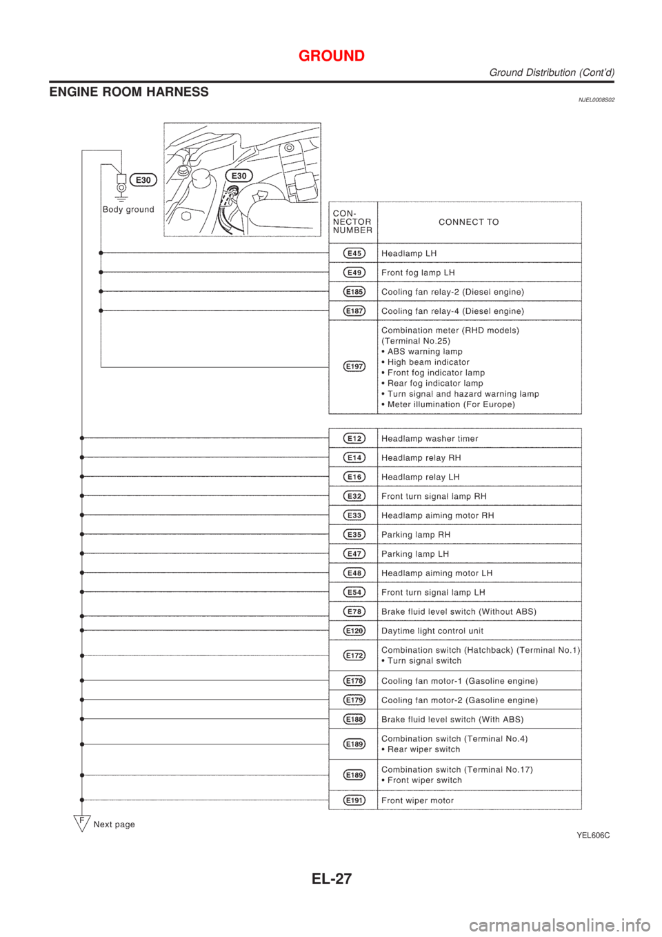
ENGINE ROOM HARNESSNJEL0008S02
YEL606C
GROUND
Ground Distribution (Cont'd)
EL-27
Page 2140 of 2493
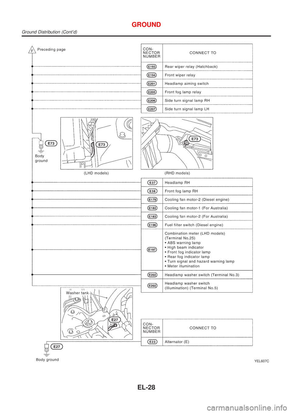
YEL607C
GROUND
Ground Distribution (Cont'd)
EL-28