dimensions NISSAN ALMERA N16 2003 Electronic User Guide
[x] Cancel search | Manufacturer: NISSAN, Model Year: 2003, Model line: ALMERA N16, Model: NISSAN ALMERA N16 2003Pages: 3189, PDF Size: 54.76 MB
Page 190 of 3189
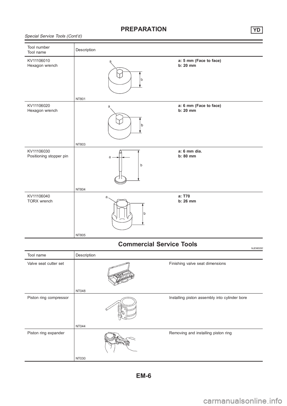
Tool number
Tool nameDescription
KV11106010
Hexagon wrench
NT801
a: 5 mm (Face to face)
b: 20 mm
KV11106020
Hexagon wrench
NT803
a: 6 mm (Face to face)
b: 20 mm
KV11106030
Positioning stopper pin
NT804
a: 6 mm dia.
b: 80 mm
KV11106040
TORX wrench
NT805
a: T70
b: 26 mm
Commercial Service ToolsNJEM0050
Tool name Description
Valve seat cutter set
NT048
Finishing valve seat dimensions
Piston ring compressor
NT044
Installing piston assembly into cylinder bore
Piston ring expander
NT030
Removing and installing piston ring
PREPARATIONYD
Special Service Tools (Cont’d)
EM-6
Page 202 of 3189
JEM116G
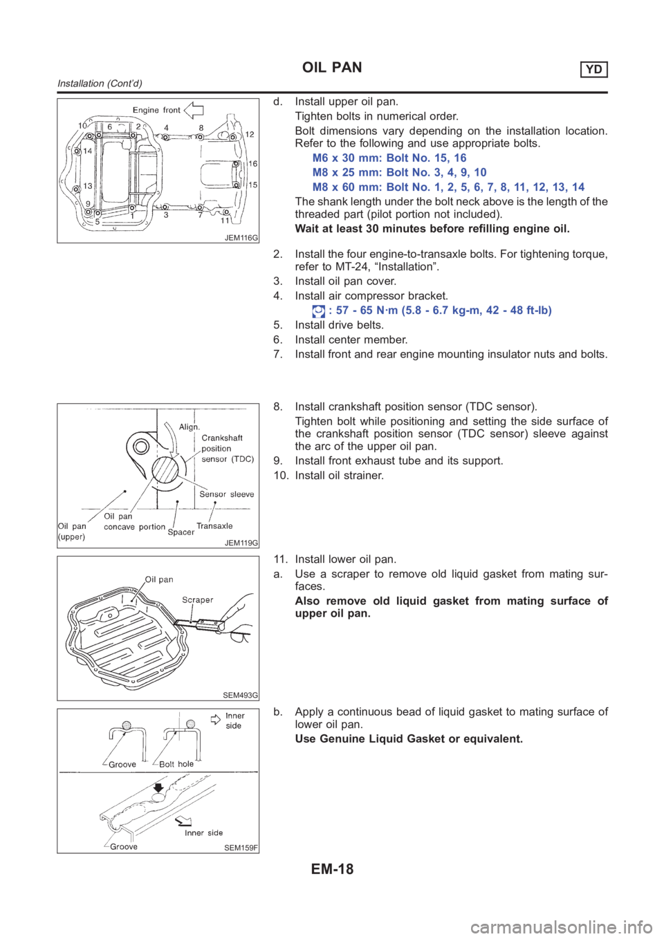
d. Install upper oil pan.
Tighten bolts in numerical order.
Bolt dimensions vary depending on the installation location.
Refer to the following and use appropriate bolts.
M6 x 30 mm: Bolt No. 15, 16
M8x25mm:BoltNo.3,4,9,10
M8x60mm:BoltNo.1,2,5,6,7,8,11,12,13,14
The shank length under the bolt neck above is the length of the
threaded part (pilot portion not included).
Wait at least 30 minutes before refilling engine oil.
2. Install the four engine-to-transaxle bolts. For tightening torque,
refer to MT-24, “Installation”.
3. Install oil pan cover.
4. Install air compressor bracket.
: 57 - 65 N·m (5.8 - 6.7 kg-m, 42 - 48 ft-lb)
5. Install drive belts.
6. Install center member.
7. Install front and rear engine mounting insulator nuts and bolts.
JEM119G
8. Install crankshaft position sensor (TDC sensor).
Tighten bolt while positioning and setting the side surface of
the crankshaft position sensor (TDC sensor) sleeve against
the arc of the upper oil pan.
9. Install front exhaust tube and its support.
10. Install oil strainer.
SEM493G
11. Install lower oil pan.
a. Use a scraper to remove old liquid gasket from mating sur-
faces.
Also remove old liquid gasket from mating surface of
upper oil pan.
SEM159F
b. Apply a continuous bead of liquid gasket to mating surface of
lower oil pan.
Use Genuine Liquid Gasket or equivalent.
OIL PANYD
Installation (Cont’d)
EM-18
Page 236 of 3189
SEM934C
JEM157G
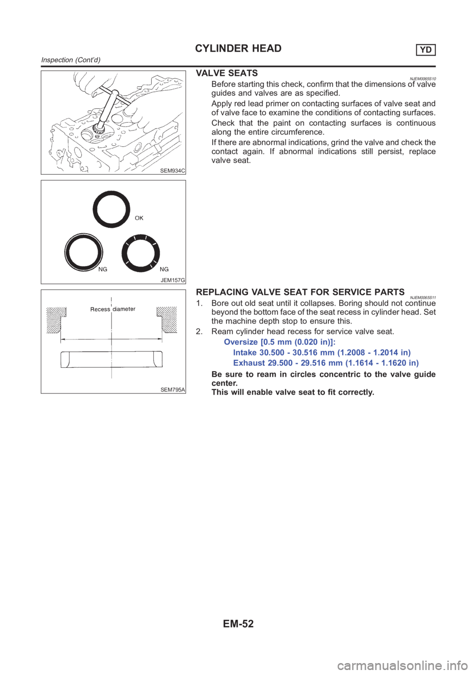
VALVE SEATSNJEM0065S10Before starting this check, confirm that the dimensions of valve
guides and valves are as specified.
Apply red lead primer on contacting surfaces of valve seat and
of valve face to examine the conditions of contacting surfaces.
Check that the paint on contacting surfaces is continuous
along the entire circumference.
If there are abnormal indications, grind the valve and check the
contact again. If abnormal indications still persist, replace
valve seat.
SEM795A
REPLACING VALVE SEAT FOR SERVICE PARTSNJEM0065S111. Bore out old seat until it collapses. Boring should not continue
beyond the bottom face of the seat recess in cylinder head. Set
the machine depth stop to ensure this.
2. Ream cylinder head recess for service valve seat.
Oversize [0.5 mm (0.020 in)]:
Intake 30.500 - 30.516 mm (1.2008 - 1.2014 in)
Exhaust 29.500 - 29.516 mm (1.1614 - 1.1620 in)
Be sure to ream in circles concentric to the valve guide
center.
This will enable valve seat to fit correctly.
CYLINDER HEADYD
Inspection (Cont’d)
EM-52
Page 237 of 3189
JEM158G
SEM301G
3. Heat cylinder head to 110 to 120°C (230 to 248°F) by soaking
in heated oil.
4. Sufficiently cool valve seat with dry ice. Force fit valve seat into
cylinder head.
WARNING:
Do not touch cold valve seat with your bare hands.
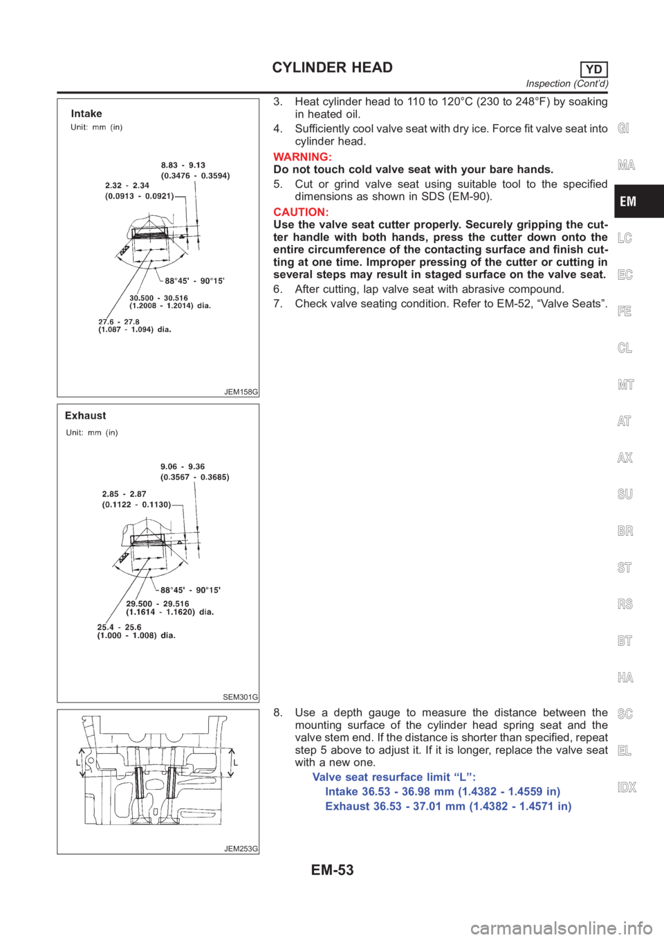
5. Cut or grind valve seat using suitable tool to the specified
dimensions as shown in SDS (EM-90).
CAUTION:
Use the valve seat cutter properly. Securely gripping the cut-
ter handle with both hands, press the cutter down onto the
entire circumference of the contacting surface and finish cut-
ting at one time. Improper pressing of the cutter or cutting in
several steps may result in staged surface on the valve seat.
6. After cutting, lap valve seat with abrasive compound.
7. Check valve seating condition. Refer to EM-52, “Valve Seats”.
JEM253G
8. Use a depth gauge to measure the distance between the
mounting surface of the cylinder head spring seat and the
valve stem end. If the distance is shorter than specified, repeat
step 5 above to adjust it. If it is longer, replace the valve seat
with a new one.
Valve seat resurface limit “L”:
Intake 36.53 - 36.98 mm (1.4382 - 1.4559 in)
Exhaust 36.53 - 37.01 mm (1.4382 - 1.4571 in)
GI
MA
LC
EC
FE
CL
MT
AT
AX
SU
BR
ST
RS
BT
HA
SC
EL
IDX
CYLINDER HEADYD
Inspection (Cont’d)
EM-53
Page 238 of 3189
SEM188A
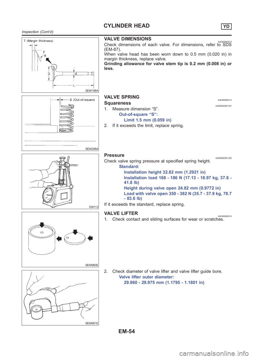
VALVE DIMENSIONSNJEM0065S12Check dimensions of each valve. For dimensions, refer to SDS
(EM-87).
When valve head has been worn down to 0.5 mm (0.020 in) in
margin thickness, replace valve.
Grinding allowance for valve stem tip is 0.2 mm (0.008 in) or
less.
SEM288A
VALVE SPRINGNJEM0065S13SquarenessNJEM0065S13011. Measure dimension “S”.
Out-of-square “S”:
Limit 1.5 mm (0.059 in)
2. If it exceeds the limit, replace spring.
EM113
PressureNJEM0065S1302Check valve spring pressure at specified spring height.
Standard:
Installation height 32.82 mm (1.2921 in)
Installation load 168 - 186 N (17.13 - 18.97 kg, 37.8 -
41.8 lb)
Height during valve open 24.82 mm (0.9772 in)
Load with valve open 350 - 382 N (35.7 - 37.9 kg, 78.7
- 83.6 lb)
If it exceeds the standard, replace spring.
SEM960E
VALVE LIFTERNJEM0065S141. Check contact and sliding surfaces for wear or scratches.
SEM961E
2. Check diameter of valve lifter and valve lifter guide bore.
Valve lifter outer diameter:
29.960 - 29.975 mm (1.1795 - 1.1801 in)
CYLINDER HEADYD
Inspection (Cont’d)
EM-54
Page 1392 of 3189
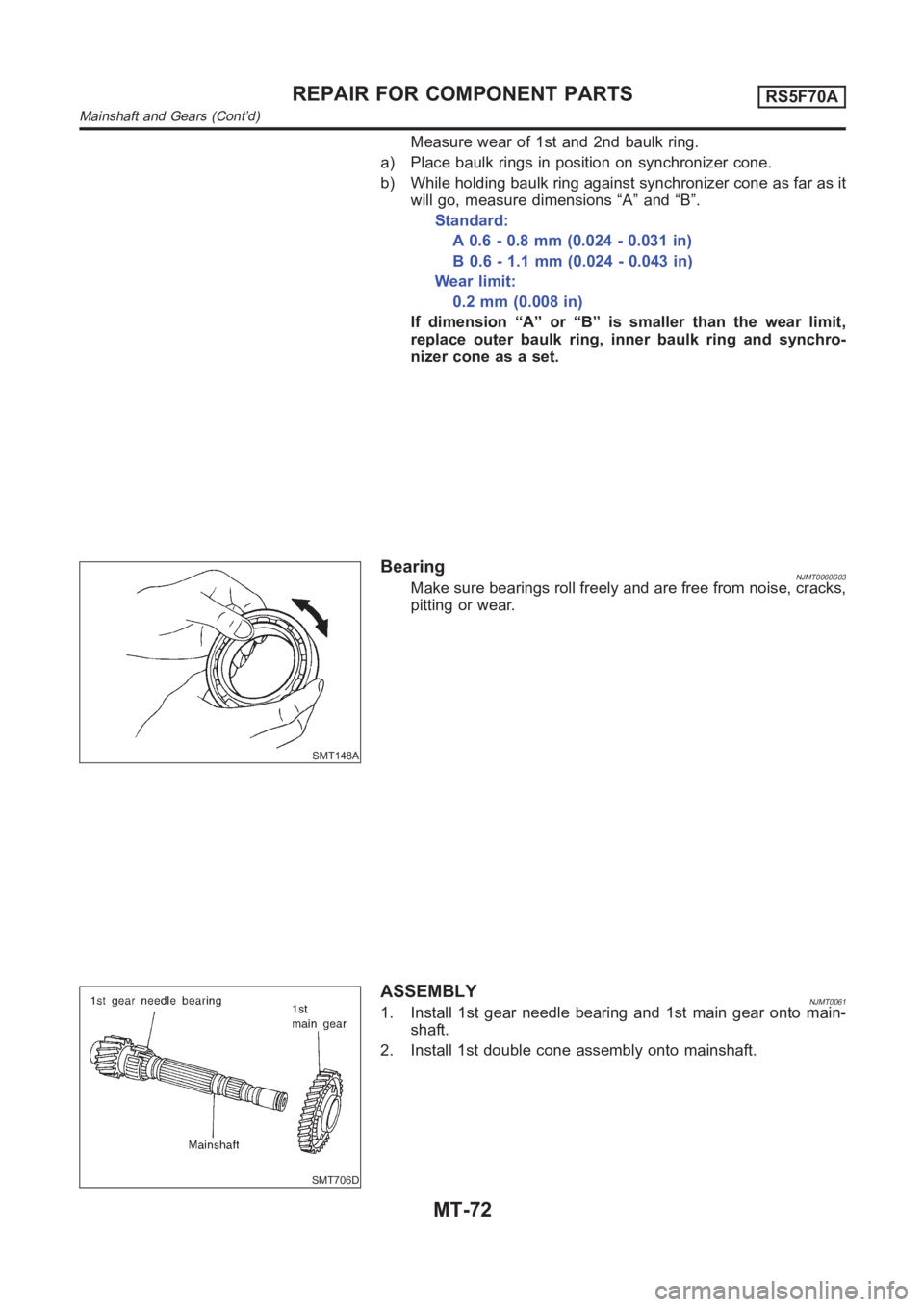
Measure wear of 1st and 2nd baulk ring.
a) Place baulk rings in position on synchronizer cone.
b) While holding baulk ring against synchronizer cone as far as it
will go, measure dimensions “A” and “B”.
Standard:
A 0.6 - 0.8 mm (0.024 - 0.031 in)
B 0.6 - 1.1 mm (0.024 - 0.043 in)
Wear limit:
0.2mm(0.008in)
If dimension “A” or “B” is smaller than the wear limit,
replace outer baulk ring, inner baulk ring and synchro-
nizer cone as a set.
SMT148A
BearingNJMT0060S03Make sure bearings roll freely and are free from noise, cracks,
pitting or wear.
SMT706D
ASSEMBLYNJMT00611. Install 1st gear needle bearing and 1st main gear onto main-
shaft.
2. Install 1st double cone assembly onto mainshaft.
REPAIR FOR COMPONENT PARTSRS5F70A
Mainshaft and Gears (Cont’d)
MT-72
Page 1425 of 3189
SMT420CA
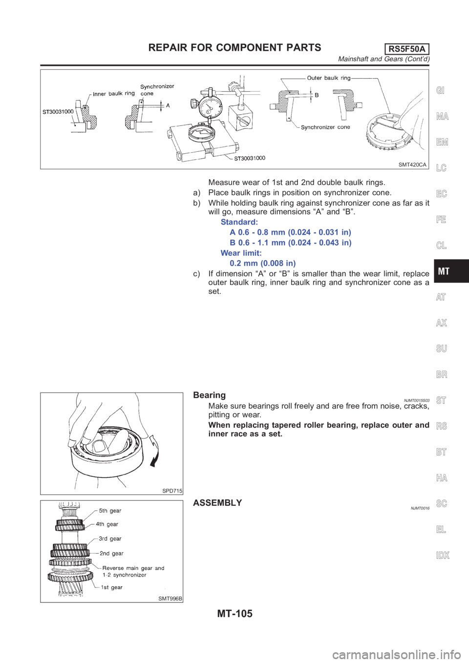
Measure wear of 1st and 2nd double baulk rings.
a) Place baulk rings in position on synchronizer cone.
b) While holding baulk ring against synchronizer cone as far as it
will go, measure dimensions “A” and “B”.
Standard:
A 0.6 - 0.8 mm (0.024 - 0.031 in)
B 0.6 - 1.1 mm (0.024 - 0.043 in)
Wear limit:
0.2mm(0.008in)
c) If dimension “A” or “B” is smaller than the wear limit, replace
outer baulk ring, inner baulk ring and synchronizer cone as a
set.
SPD715
BearingNJMT0015S03Make sure bearings roll freely and are free from noise, cracks,
pitting or wear.
When replacing tapered roller bearing, replace outer and
inner race as a set.
SMT996B
ASSEMBLYNJMT0016
GI
MA
EM
LC
EC
FE
CL
AT
AX
SU
BR
ST
RS
BT
HA
SC
EL
IDX
REPAIR FOR COMPONENT PARTSRS5F50A
Mainshaft and Gears (Cont’d)
MT-105
Page 1865 of 3189
![NISSAN ALMERA N16 2003 Electronic User Guide ON-VEHICLE SERVICE
AT-409
[ALL]
D
E
F
G
H
I
J
K
L
MA
B
AT
Differential Side Oil Seal ReplacementECS007T2
1. Remove drive shaft assemblies. Refer to AX-10, "FRONT
DRIVE SHAFT".
2. Remove oil se](/img/5/57350/w960_57350-1864.png "NISSAN ALMERA N16 2003 Electronic User Guide ON-VEHICLE SERVICE
AT-409
[ALL]
D
E
F
G
H
I
J
K
L
MA
B
AT
Differential Side Oil Seal ReplacementECS007T2
1. Remove drive shaft assemblies. Refer to AX-10, \"FRONT
DRIVE SHAFT\".
2. Remove oil se")
ON-VEHICLE SERVICE
AT-409
[ALL]
D
E
F
G
H
I
J
K
L
MA
B
AT
Differential Side Oil Seal ReplacementECS007T2
1. Remove drive shaft assemblies. Refer to AX-10, "FRONT
DRIVE SHAFT".
2. Remove oil seals.
3. Install oil seals.
●Apply ATF to oil seal surface before installing.
●Drift for installing
●Install oil seals so that dimensions “A” and “B” are within
specifications.
Unit: mm (in)
4. Reinstall any part removed.
Revolution Sensor ReplacementECS007T3
1. Disconnect revolution sensor harness connector.
2. Remove harness bracket from A/T.
3. Remove revolution sensor from A/T.
4. Reinstall any part removed.
Always use new sealing parts.
SAT905D
AAT976
AB
5.5 to 6.5 (0.217 to 0.256)−0.5 to 0.5 (−0.020 to 0.020)
MCIB9018E
SAT303G
Page 1952 of 3189
![NISSAN ALMERA N16 2003 Electronic User Guide AT-496
[ALL]
ASSEMBLY
1. Remove transmission case and final drive assembly from converter housing.
2. Select proper thickness of reduction pinion gear bearing adjusting shim using the following proced](/img/5/57350/w960_57350-1951.png "NISSAN ALMERA N16 2003 Electronic User Guide AT-496
[ALL]
ASSEMBLY
1. Remove transmission case and final drive assembly from converter housing.
2. Select proper thickness of reduction pinion gear bearing adjusting shim using the following proced")
AT-496
[ALL]
ASSEMBLY
1. Remove transmission case and final drive assembly from converter housing.
2. Select proper thickness of reduction pinion gear bearing adjusting shim using the following procedures.
a. Place reduction pinion gear on transmission case as shown.
b. Place idler gear bearing on transmission case.
c. Measure dimensions “B” “C” and “D” and calculate dimension
“A”.
●Measure dimension “B” between the end of reduction pinion
gear and the surface of transmission case.
●Measure dimension “B” in at least two places.
●Measure dimension “C” between the surface of idler gear
bearing inner race and the surface of transmission case.
●Measure dimension “C” in at least two places.
●Measure dimension “D” between the end of reduction pinion
gear and the adjusting shim mating surface of reduction pin-
ion gear.
●Measure dimension “D” in at least two places.
●Calculate dimension “A”.A = D − (B + C)
“A”: Distance between the surface of idler gear bear-
ing inner race and the adjusting shim mating
surface of reduction pinion gear.
SAT333DA
SAT334DA
SAT335D
A = D − (B + C)
SAT336DA
Page 1955 of 3189
![NISSAN ALMERA N16 2003 Electronic User Guide ASSEMBLY
AT-499
[ALL]
D
E
F
G
H
I
J
K
L
MA
B
AT
4. Measure dimensions “1 ” and “2 ” at side cover and then cal-
culate dimension “A”.
●Measure dimension “1 ” and “2 ” in at l](/img/5/57350/w960_57350-1954.png "NISSAN ALMERA N16 2003 Electronic User Guide ASSEMBLY
AT-499
[ALL]
D
E
F
G
H
I
J
K
L
MA
B
AT
4. Measure dimensions “1 ” and “2 ” at side cover and then cal-
culate dimension “A”.
●Measure dimension “1 ” and “2 ” in at l")
ASSEMBLY
AT-499
[ALL]
D
E
F
G
H
I
J
K
L
MA
B
AT
4. Measure dimensions “1 ” and “2 ” at side cover and then cal-
culate dimension “A”.
●Measure dimension “1 ” and “2 ” in at least two
places.
5. Measure dimensions “
2 ” and “3 ” and then calculate dimen-
sion “B”.
●Measure “2 ” and “3 ” in at least two places.
6. Select proper thickness of adjusting shim so that output shaft
end play (clearance between side cover and output shaft bear-
ing) is within specifications.
7. Install adjusting shim on output shaft bearing.
8. Apply locking sealant to transmission case as shown in illustra-
tion.
9. Install side cover on transmission case.
●Apply locking sealant to the mating surface of transmis-
sion case.“A”: Distance between transmission case fitting
surface and adjusting shim mating surface.
A =
1−2
2
:Height of gauge
SAT874DA
“B”: Distance between the end of output shaft bear-
ing outer race and the side cover fitting sur-
face of transmission case.
B =
2−3
2
:Height of gauge
SAT875DA
Output shaft end play (A − B):
0 - 0.5 mm (0 - 0.020 in)
Output shaft end play adjusting shims:
Refer to AT- 5 1 5 , "
SERVICE DATA AND SPECIFICA-
TIONS (SDS)" .
SAT440D
SAT441D
SAT442D