Fan motor NISSAN ALMERA N16 2003 Electronic Owner's Manual
[x] Cancel search | Manufacturer: NISSAN, Model Year: 2003, Model line: ALMERA N16, Model: NISSAN ALMERA N16 2003Pages: 3189, PDF Size: 54.76 MB
Page 2009 of 3189
TROUBLE DIAGNOSIS
ATC-29
C
D
E
F
G
H
I
K
L
MA
B
AT C
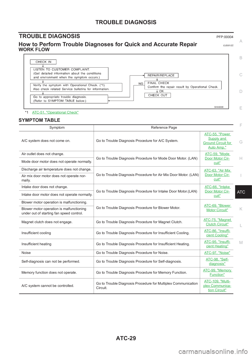
TROUBLE DIAGNOSISPFP:00004
How to Perform Trouble Diagnoses for Quick and Accurate RepairEJS001ZC
WORK FLOW
SYMPTOM TABLE
*1AT C - 5 1 , "Operational Check"
SHA900E
Symptom Reference Page
A/C system does not come on. Go to Trouble Diagnosis Procedure for A/C System.ATC-55, "
Power
Supply and
Ground Circuit for
Auto Amp."
Air outlet does not change.
Go to Trouble Diagnosis Procedure for Mode Door Motor. (LAN)AT C - 5 9 , "Mode
Door Motor Cir-
cuit"Mode door motor does not operate normally.
Discharge air temperature does not change.
Go to Trouble Diagnosis Procedure for Air Mix Door Motor. (LAN)ATC-63, "
Air Mix
Door Motor Cir-
cuit"Air mix door motor does not operate nor-
mally.
Intake door does not change.
Go to Trouble Diagnosis Procedure for Intake Door Motor.(LAN)AT C - 6 6 , "
Intake
Door Motor Cir-
cuit"Intake door motor does not operate normally.
Blower motor operation is malfunctioning.
Go to Trouble Diagnosis Procedure for Blower Motor.ATC-69, "
Blower
Motor Circuit"Blower motor operation is malfunctioning
under out of starting fan speed control.
Magnet clutch does not engage. Go to Trouble Diagnosis Procedure for Magnet Clutch.AT C - 7 5 , "
Magnet
Clutch Circuit"
Insufficient cooling Go to Trouble Diagnosis Procedure for Insufficient Cooling.AT C - 8 6 , "Insuffi-
cient Cooling"
Insufficient heating Go to Trouble Diagnosis Procedure for Insufficient Heating.AT C - 9 5 , "Insuffi-
cient Heating"
Noise Go to Trouble Diagnosis Procedure for Noise.ATC-97, "Noise"
Self-diagnosis can not be performed. Go to Trouble Diagnosis Procedure for Self-diagnosis.AT C - 9 8 , "Self-
diagnosis"
Memory function does not operate. Go to Trouble Diagnosis Procedure for Memory Function.AT C - 9 9 , "Memory
Function"
A/C system cannot be controlled.Go to Trouble Diagnosis Procedure for Multiplex Communication
Circuit.ATC-109, "
Multi-
plex Communica-
tion Circuit"
Page 2021 of 3189
TROUBLE DIAGNOSIS
ATC-41
C
D
E
F
G
H
I
K
L
MA
B
AT C
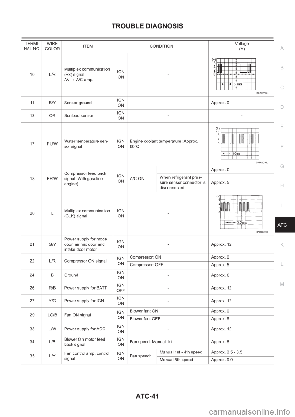
10 L/RMultiplex communication
(Rx) signal
AV → A/C amp.IGN
ON-
11 B/Y Sensor ground IGN
ON-Approx. 0
12 OR Sunload sensorIGN
ON--
17 PU/WWater temperature sen-
sor signalIGN
ONEngine coolant temperature: Approx.
60°C
18 BR/WCompressor feed back
signal (With gasoline
engine)IGN
ONA/C ON-Approx. 0
When refrigerant pres-
sure sensor connector is
disconnected.Approx. 5
20 LMultiplex communication
(CLK) signalIGN
ON-
21 G/YPower supply for mode
door, air mix door and
intake door motorIGN
ON-Approx. 12
22 L/R Compressor ON signalIGN
ONCompressor: ON Approx. 0
Compressor: OFF Approx. 5
24 B GroundIGN
ON-Approx. 0
26 R/B Power supply for BATTIGN
OFF-Approx. 12
27 Y/G Power supply for IGNIGN
ON-Approx. 12
29 LG/B Fan ON signalIGN
ONBlower fan: ON Approx. 0
Blower fan: OFF Approx. 5
33 L/W Power supply for ACCIGN
ON-Approx. 12
34 L/BBlower fan motor feed
back signalIGN
ONFan speed: Manual 1st Approx. 8
35 L/YFan control amp. control
signalIGN
ONFan speed:Manual 1st - 4th speed Approx. 2.5 - 3.5
Manual 5th speed Approx. 9.0 TERMI-
NAL NO.WIRE
COLORITEM CONDITIONVo lta g e
(V)
RJIA0213E
SKIA0056J
HAK0363D
Page 2022 of 3189
ATC-42
TROUBLE DIAGNOSIS
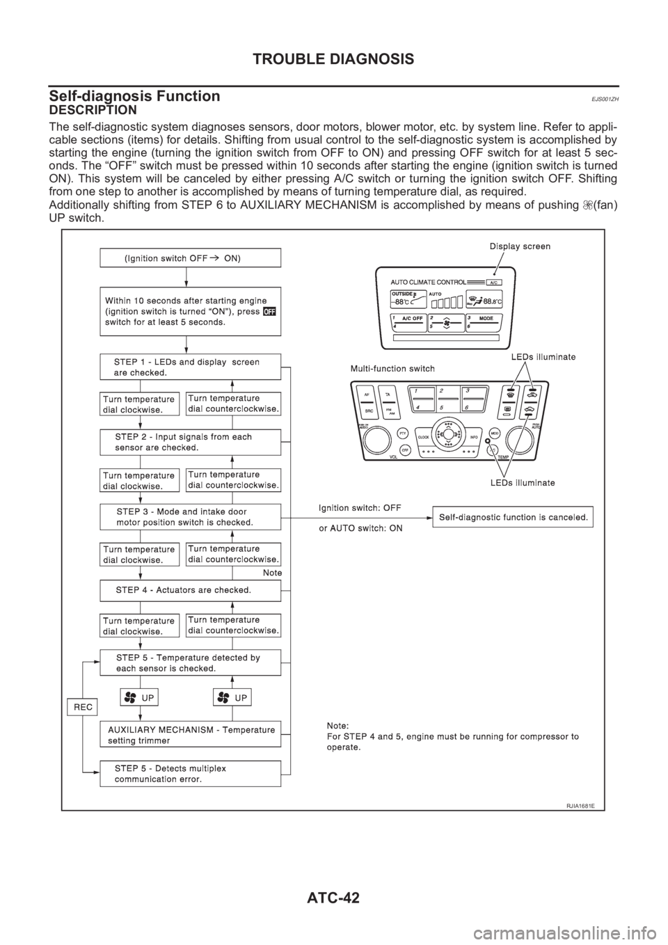
Self-diagnosis Function
EJS001ZH
DESCRIPTION
The self-diagnostic system diagnoses sensors, door motors, blower motor, etc. by system line. Refer to appli-
cable sections (items) for details. Shifting from usual control to the self-diagnostic system is accomplished by
starting the engine (turning the ignition switch from OFF to ON) and pressing OFF switch for at least 5 sec-
onds. The “OFF” switch must be pressed within 10 seconds after starting the engine (ignition switch is turned
ON). This system will be canceled by either pressing A/C switch or turning the ignition switch OFF. Shifting
from one step to another is accomplished by means of turning temperature dial, as required.
Additionally shifting from STEP 6 to AUXILIARY MECHANISM is accomplished by means of pushing (fan)
UP switch.
RJIA1681E
Page 2026 of 3189
ATC-46
TROUBLE DIAGNOSIS
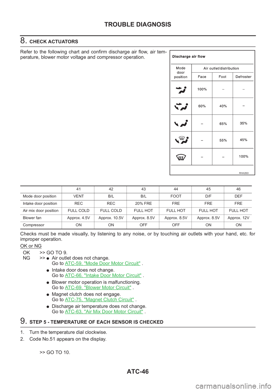
8. CHECK ACTUATORS
Refer to the following chart and confirm discharge air flow, air tem-
perature, blower motor voltage and compressor operation.
Checks must be made visually, by listening to any noise, or by touching air outlets with your hand, etc. for
improper operation.
OK or NG
OK >> GO TO 9.
NG >>
●Air outlet does not change.
Go to AT C - 5 9 , "
Mode Door Motor Circuit" .
●Intake door does not change.
Go to AT C - 6 6 , "
Intake Door Motor Circuit" .
●Blower motor operation is malfunctioning.
Go to AT C - 6 9 , "
Blower Motor Circuit" .
●Magnet clutch does not engage.
Go to AT C - 7 5 , "
Magnet Clutch Circuit" .
●Discharge air temperature does not change.
Go to AT C - 6 3 , "
Air Mix Door Motor Circuit" .
9. STEP 5 - TEMPERATURE OF EACH SENSOR IS CHECKED
1. Turn the temperature dial clockwise.
2. Code No.51 appears on the display.
>> GO TO 10.
RHA280I
41 42 43 44 45 46
Mode door position VENT B/L B/L FOOT D/F DEF
Intake door position REC REC 20% FRE FRE FRE FRE
Air mix door position FULL COLD FULL COLD FULL HOT FULL HOT FULL HOTFULL HOT
Blower fan Approx. 4.5V Approx. 10.5V Approx. 8.5V Approx. 8.5V Approx. 8.5V Approx. 12V
Compressor ON ON OFF OFF ON ON
Page 2029 of 3189
TROUBLE DIAGNOSIS
ATC-49
C
D
E
F
G
H
I
K
L
MA
B
AT C
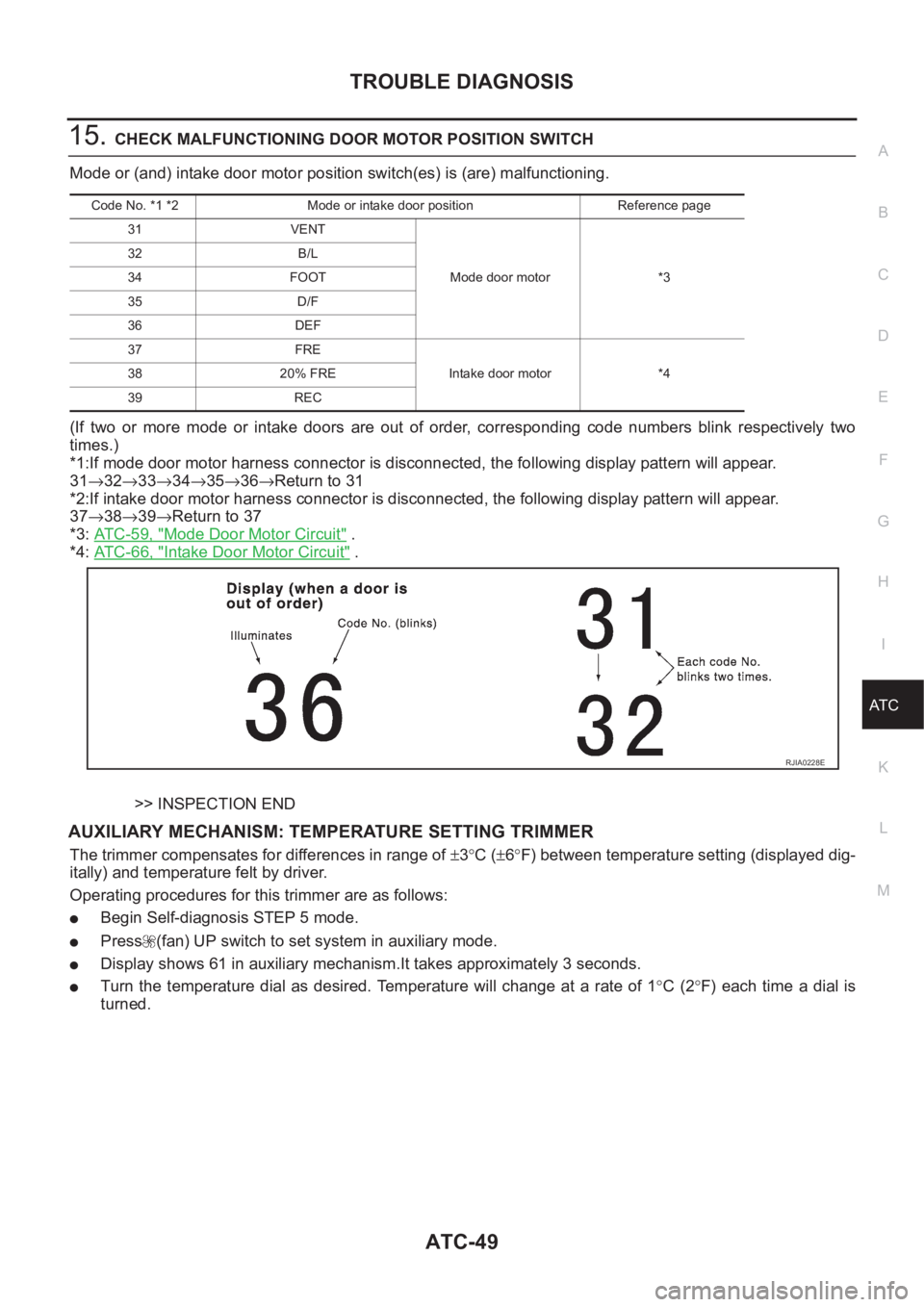
15.CHECK MALFUNCTIONING DOOR MOTOR POSITION SWITCH
Mode or (and) intake door motor position switch(es) is (are) malfunctioning.
(If two or more mode or intake doors are out of order, corresponding code numbers blink respectively two
times.)
*1:If mode door motor harness connector is disconnected, the following display pattern will appear.
31→32→33→34→35→36→Return to 31
*2:If intake door motor harness connector is disconnected, the following display pattern will appear.
37→38→39→Return to 37
*3: AT C - 5 9 , "
Mode Door Motor Circuit" .
*4: AT C - 6 6 , "
Intake Door Motor Circuit" .
>> INSPECTION END
AUXILIARY MECHANISM: TEMPERATURE SETTING TRIMMER
The trimmer compensates for differences in range of ±3°C (±6°F) between temperature setting (displayed dig-
itally) and temperature felt by driver.
Operating procedures for this trimmer are as follows:
●Begin Self-diagnosis STEP 5 mode.
●Press (fan) UP switch to set system in auxiliary mode.
●Display shows 61 in auxiliary mechanism.It takes approximately 3 seconds.
●Turn the temperature dial as desired. Temperature will change at a rate of 1°C (2°F) each time a dial is
turned.
Code No. *1 *2 Mode or intake door position Reference page
31 VENT
Mode door motor *3 32 B/L
34 FOOT
35 D/F
36 DEF
37 FRE
Intake door motor *4 38 20% FRE
39 REC
RJIA0228E
Page 2031 of 3189
TROUBLE DIAGNOSIS
ATC-51
C
D
E
F
G
H
I
K
L
MA
B
AT C
Operational CheckEJS001ZI
The purpose of the operational check is to confirm that the system operates properly.
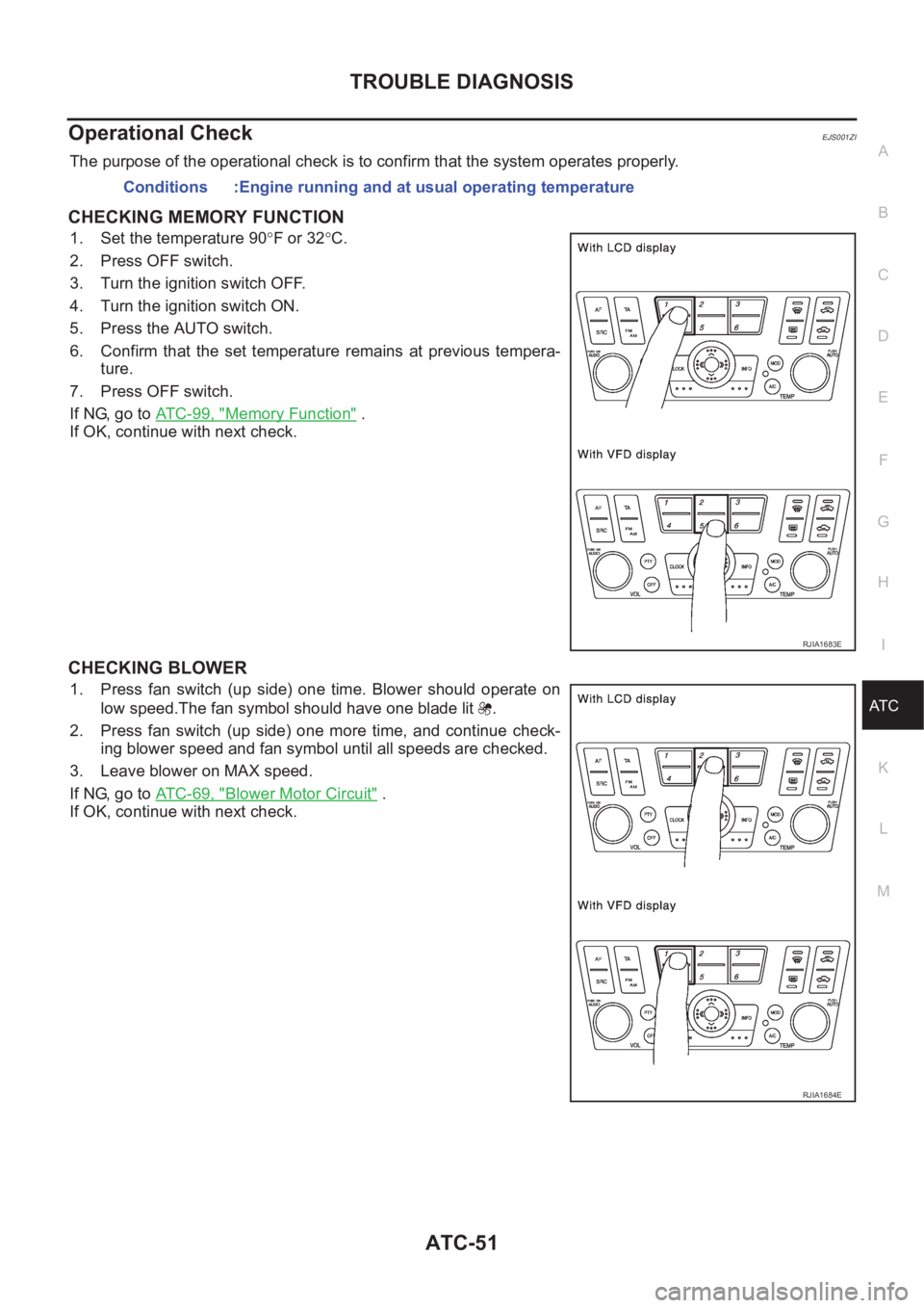
CHECKING MEMORY FUNCTION
1. Set the temperature 90°F or 32°C.
2. Press OFF switch.
3. Turn the ignition switch OFF.
4. Turn the ignition switch ON.
5. Press the AUTO switch.
6. Confirm that the set temperature remains at previous tempera-
ture.
7. Press OFF switch.
If NG, go to ATC-99, "
Memory Function" .
If OK, continue with next check.
CHECKING BLOWER
1. Press fan switch (up side) one time. Blower should operate on
low speed.The fan symbol should have one blade lit .
2. Press fan switch (up side) one more time, and continue check-
ing blower speed and fan symbol until all speeds are checked.
3. Leave blower on MAX speed.
If NG, go to ATC-69, "
Blower Motor Circuit" .
If OK, continue with next check.Conditions :Engine running and at usual operating temperature
RJIA1683E
RJIA1684E
Page 2049 of 3189
TROUBLE DIAGNOSIS
ATC-69
C
D
E
F
G
H
I
K
L
MA
B
AT C
Blower Motor CircuitEJS001ZO
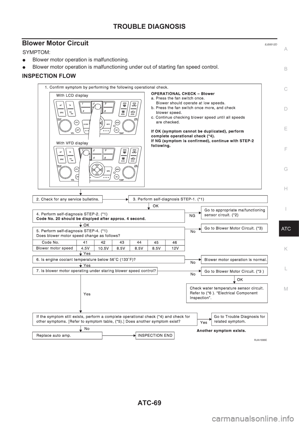
SYMPTOM:
●Blower motor operation is malfunctioning.
●Blower motor operation is malfunctioning under out of starting fan speed control.
INSPECTION FLOW
RJIA1696E
Page 2050 of 3189
ATC-70
TROUBLE DIAGNOSIS
SYSTEM DESCRIPTION
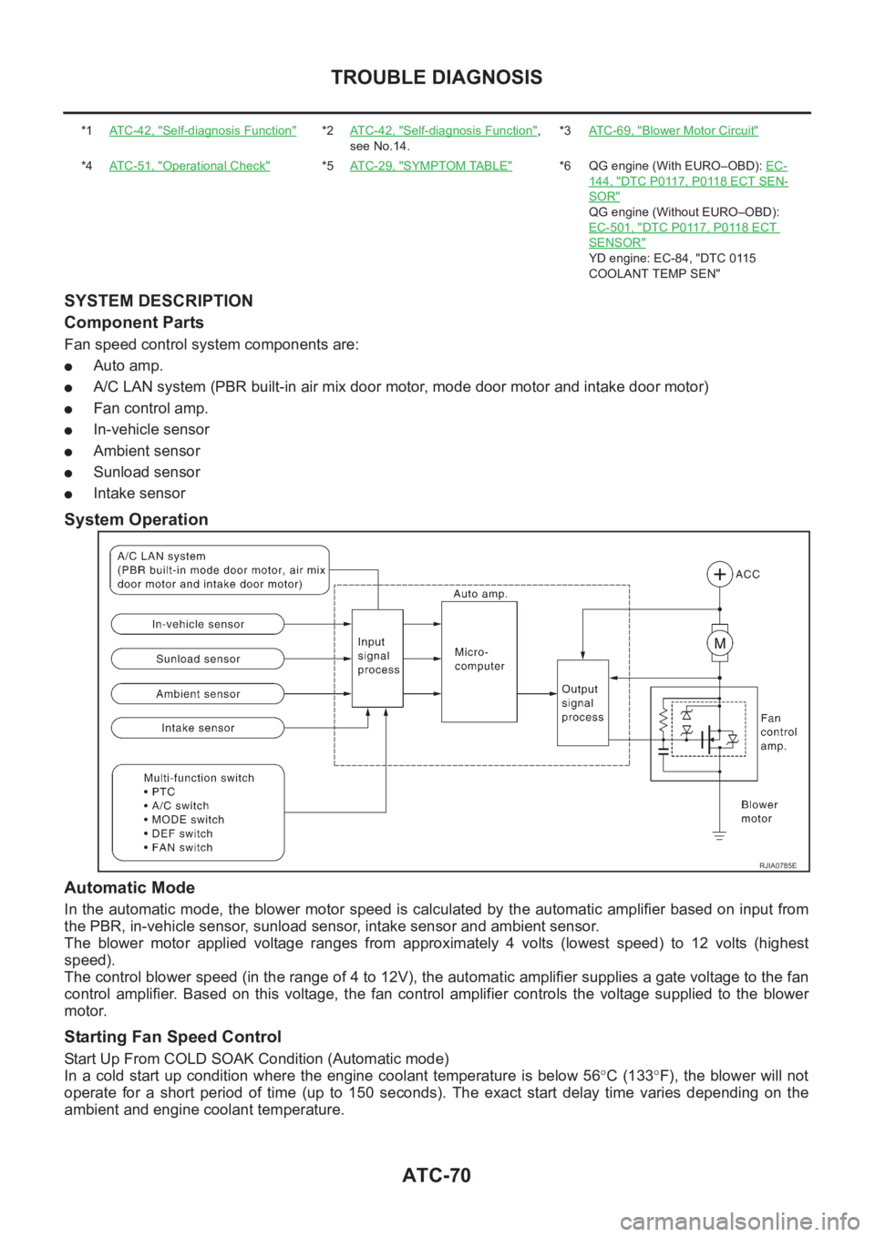
Component Parts
Fan speed control system components are:
●Auto amp.
●A/C LAN system (PBR built-in air mix door motor, mode door motor and intake door motor)
●Fan control amp.
●In-vehicle sensor
●Ambient sensor
●Sunload sensor
●Intake sensor
System Operation
Automatic Mode
In the automatic mode, the blower motor speed is calculated by the automatic amplifier based on input from
the PBR, in-vehicle sensor, sunload sensor, intake sensor and ambient sensor.
The blower motor applied voltage ranges from approximately 4 volts (lowest speed) to 12 volts (highest
speed).
The control blower speed (in the range of 4 to 12V), the automatic amplifier supplies a gate voltage to the fan
control amplifier. Based on this voltage, the fan control amplifier controls the voltage supplied to the blower
motor.
Starting Fan Speed Control
Start Up From COLD SOAK Condition (Automatic mode)
In a cold start up condition where the engine coolant temperature is below 56°C (133°F), the blower will not
operate for a short period of time (up to 150 seconds). The exact start delay time varies depending on the
ambient and engine coolant temperature.
*1AT C - 4 2 , "Self-diagnosis Function"*2AT C - 4 2 , "Self-diagnosis Function",
see No.14.*3AT C - 6 9 , "Blower Motor Circuit"
*4AT C - 5 1 , "Operational Check"*5AT C - 2 9 , "SYMPTOM TABLE"*6 QG engine (With EURO–OBD): EC-
144, "DTC P0117, P0118 ECT SEN-
SOR"
QG engine (Without EURO–OBD):
EC-501, "
DTC P0117, P0118 ECT
SENSOR"
YD engine: EC-84, "DTC 0115
COOLANT TEMP SEN"
RJIA0785E
Page 2051 of 3189
TROUBLE DIAGNOSIS
ATC-71
C
D
E
F
G
H
I
K
L
MA
B
AT C
In the most extreme case (very low ambient) the blower starting delay will be 150 seconds as described
above. After this delay, the blower will operate at low speed until the engine coolant temperature rises above
56°C (133°F), at which time the blower speed will increase to the objective speed.
Start Up From Usual or HOT SOAK Condition (Automatic mode)
The blower will begin operation momentarily after the A/C button is pushed. The blower speed will gradually
rise to the objective speed over a time period of 3 seconds or less (actual time depends on the objective
blower speed).
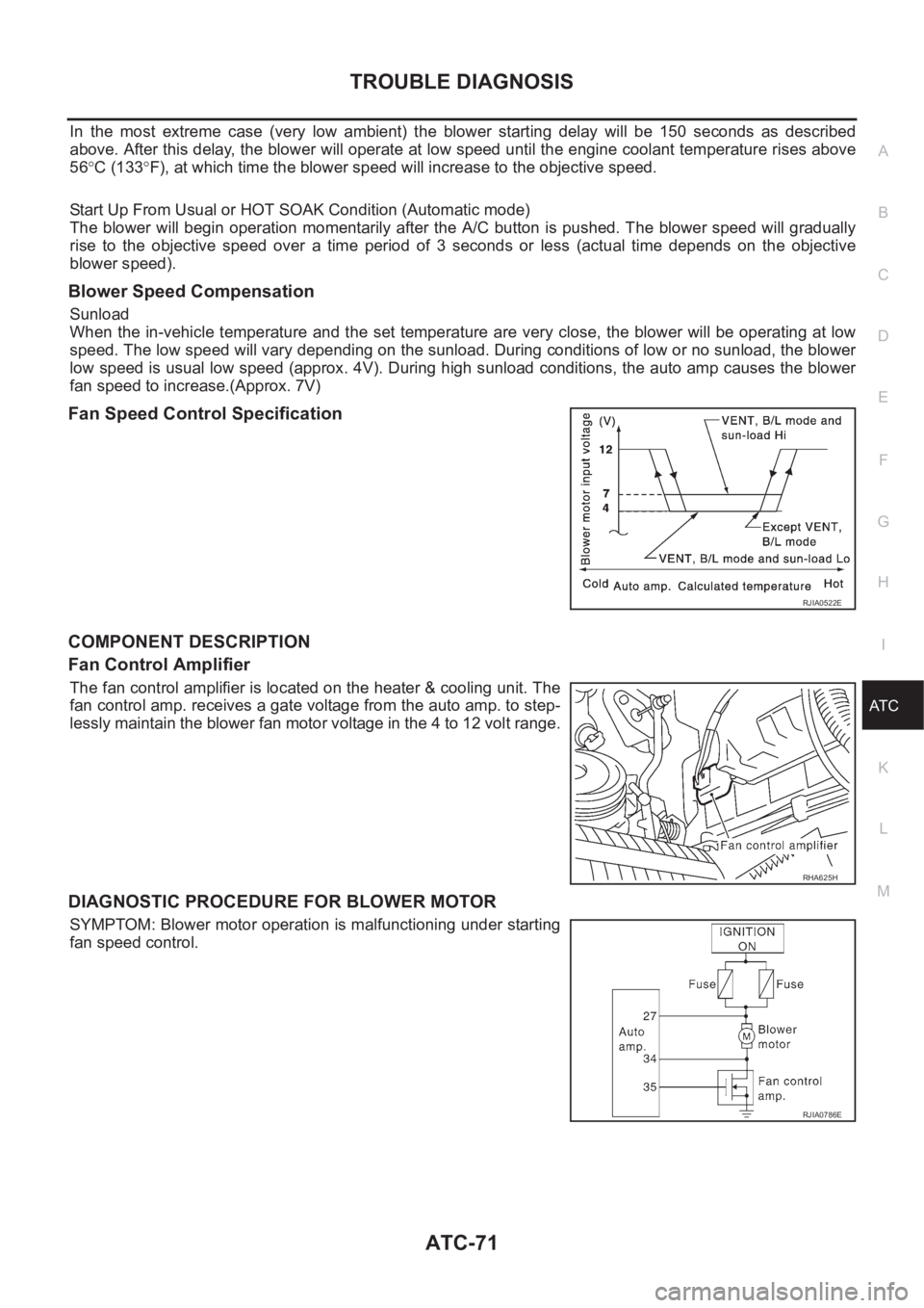
Blower Speed Compensation
Sunload
When the in-vehicle temperature and the set temperature are very close, the blower will be operating at low
speed. The low speed will vary depending on the sunload. During conditions of low or no sunload, the blower
low speed is usual low speed (approx. 4V). During high sunload conditions, the auto amp causes the blower
fan speed to increase.(Approx. 7V)
Fan Speed Control Specification
COMPONENT DESCRIPTION
Fan Control Amplifier
The fan control amplifier is located on the heater & cooling unit. The
fan control amp. receives a gate voltage from the auto amp. to step-
lessly maintain the blower fan motor voltage in the 4 to 12 volt range.
DIAGNOSTIC PROCEDURE FOR BLOWER MOTOR
SYMPTOM: Blower motor operation is malfunctioning under starting
fan speed control.
RJIA0522E
RHA625H
RJIA0786E
Page 2052 of 3189
ATC-72
TROUBLE DIAGNOSIS
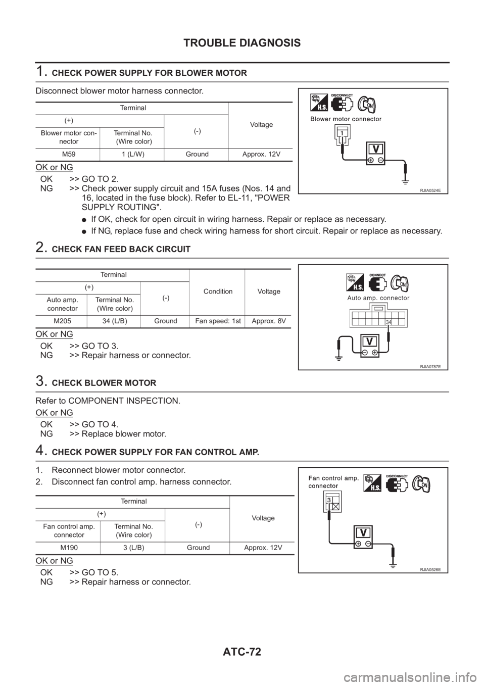
1. CHECK POWER SUPPLY FOR BLOWER MOTOR
Disconnect blower motor harness connector.
OK or NG
OK >> GO TO 2.
NG >> Check power supply circuit and 15A fuses (Nos. 14 and
16, located in the fuse block). Refer to EL-11, "POWER
SUPPLY ROUTING".
●If OK, check for open circuit in wiring harness. Repair or replace as necessary.
●If NG, replace fuse and check wiring harness for short circuit. Repair or replace as necessary.
2. CHECK FAN FEED BACK CIRCUIT
OK or NG
OK >> GO TO 3.
NG >> Repair harness or connector.
3. CHECK BLOWER MOTOR
Refer to COMPONENT INSPECTION.
OK or NG
OK >> GO TO 4.
NG >> Replace blower motor.
4. CHECK POWER SUPPLY FOR FAN CONTROL AMP.
1. Reconnect blower motor connector.
2. Disconnect fan control amp. harness connector.
OK or NG
OK >> GO TO 5.
NG >> Repair harness or connector.
Terminal
Vo l ta g e (+)
(-)
Blower motor con-
nectorTerminal No.
(Wire color)
M59 1 (L/W) Ground Approx. 12V
RJIA0524E
Te r m i n a l
Condition Voltage (+)
(-)
Auto amp.
connectorTerminal No.
(Wire color)
M205 34 (L/B) Ground Fan speed: 1st Approx. 8V
RJIA0787E
Te r m i n a l
Voltag e (+)
(-)
Fan control amp.
connectorTerminal No.
(Wire color)
M190 3 (L/B) Ground Approx. 12V
RJIA0526E