brake fluid NISSAN ALMERA N16 2003 Electronic Owner's Manual
[x] Cancel search | Manufacturer: NISSAN, Model Year: 2003, Model line: ALMERA N16, Model: NISSAN ALMERA N16 2003Pages: 3189, PDF Size: 54.76 MB
Page 1460 of 3189

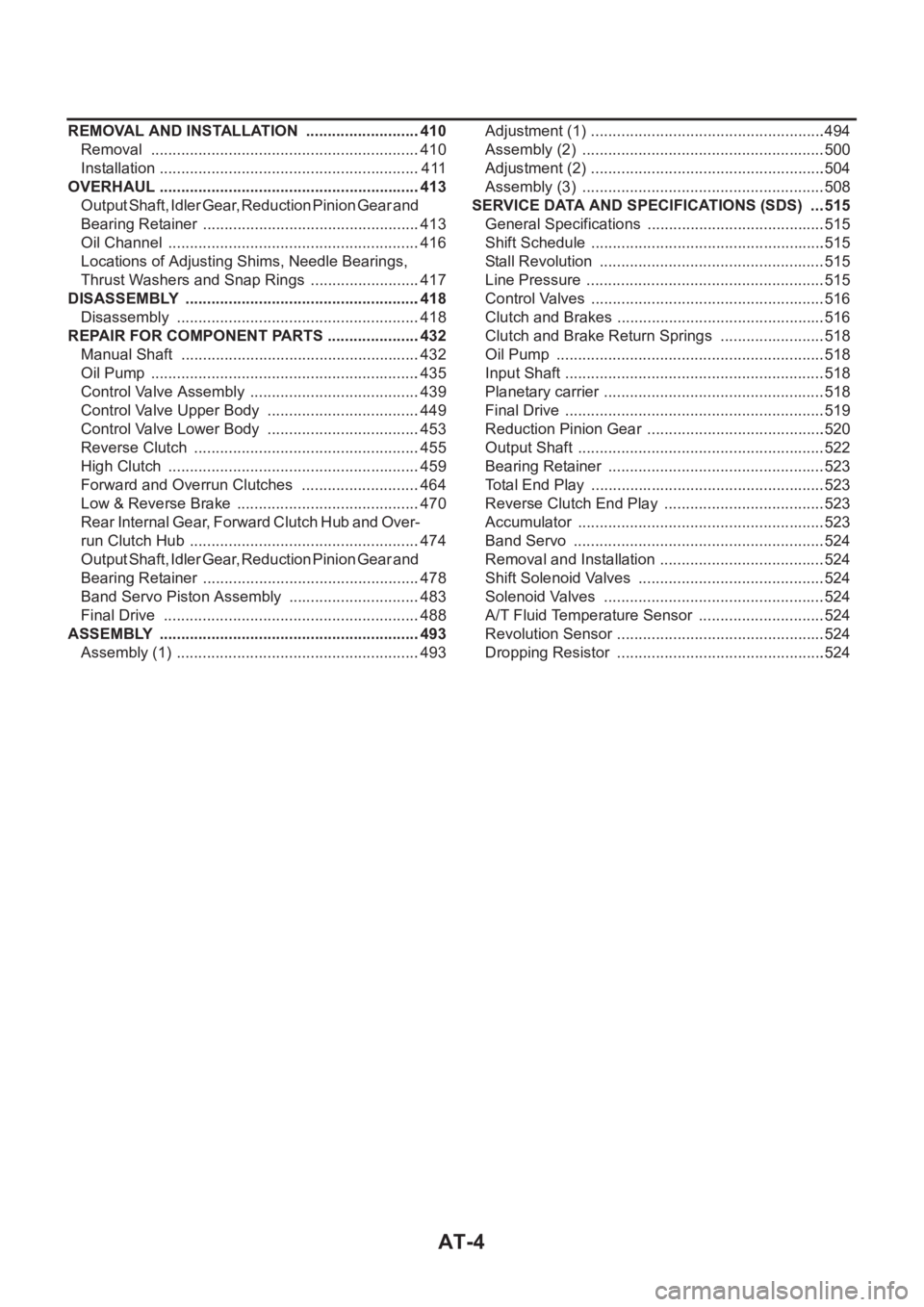
AT-4
REMOVAL AND INSTALLATION ...........................410
Removal ...............................................................410
Installation .............................................................411
OVERHAUL .............................................................413
Output Shaft, Idler Gear, Reduction Pinion Gear and
Bearing Retainer ...................................................413
Oil Channel ...........................................................416
Locations of Adjusting Shims, Needle Bearings,
Thrust Washers and Snap Rings ..........................417
DISASSEMBLY .......................................................418
Disassembly .........................................................418
REPAIR FOR COMPONENT PARTS ......................432
Manual Shaft ........................................................432
Oil Pump ...............................................................435
Control Valve Assembly ........................................439
Control Valve Upper Body ....................................449
Control Valve Lower Body ....................................453
Reverse Clutch .....................................................455
High Clutch ...........................................................459
Forward and Overrun Clutches ............................464
Low & Reverse Brake ...........................................470
Rear Internal Gear, Forward Clutch Hub and Over-
run Clutch Hub ......................................................474
Output Shaft, Idler Gear, Reduction Pinion Gear and
Bearing Retainer ...................................................478
Band Servo Piston Assembly ...............................483
Final Drive ............................................................488
ASSEMBLY .............................................................493
Assembly (1) .........................................................493Adjustment (1) .......................................................494
Assembly (2) .........................................................500
Adjustment (2) .......................................................504
Assembly (3) .........................................................508
SERVICE DATA AND SPECIFICATIONS (SDS) ....515
General Specifications ......................................... .515
Shift Schedule .......................................................515
Stall Revolution .....................................................515
Line Pressure ........................................................515
Control Valves .......................................................516
Clutch and Brakes .................................................516
Clutch and Brake Return Springs .........................518
Oil Pump ......................................................
.........518
Input Shaft .............................................................518
Planetary carrier ....................................................518
Final Drive .............................................................519
Reduction Pinion Gear ..........................................520
Output Shaft ..........................................................522
Bearing Retainer ...................................................523
Total End Play .......................................................523
Reverse Clutch End Play ......................................523
Accumulator ..........................................................523
Band Servo ...........................................................524
Removal and Installation .......................................524
Shift Solenoid Valves ............................................524
Solenoid Valves ....................................................524
A/T Fluid Temperature Sensor ..............................524
Revolution Sensor .................................................524
Dropping Resistor .................................................524
Page 1469 of 3189

A/T FLUID
AT-13
D
E
F
G
H
I
J
K
L
MA
B
AT
A/T FLUIDPFP:KLE40
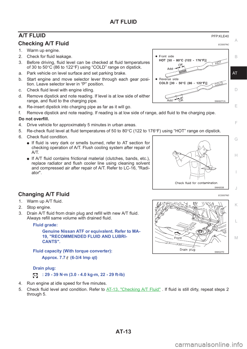
Checking A/T FluidECS007NC
1. Warm up engine.
2. Check for fluid leakage.
3. Before driving, fluid level can be checked at fluid temperatures
of 30 to 50°C (86 to 122°F) using “COLD” range on dipstick.
a. Park vehicle on level surface and set parking brake.
b. Start engine and move selector lever through each gear posi-
tion. Leave selector lever in “P” position.
c. Check fluid level with engine idling.
d. Remove dipstick and note reading. If level is at low side of either
range, and fluid to the charging pipe.
e. Re-insert dipstick into charging pipe as far as it will go.
f. Remove dipstick and note reading. If reading is at low side of range, add fluid to the charging pipe.
Do not overfill.
4. Drive vehicle for approximately 5 minutes in urban areas.
5. Re-check fluid level at fluid temperatures of 50 to 80°C (122 to 176°F) using “HOT” range on dipstick.
6. Check fluid condition.
●If fluid is very dark or smells burned, refer to AT section for
checking operation of A/T. Flush cooling system after repair of
A/T.
●If A/T fluid contains frictional material (clutches, bands, etc.),
replace radiator and flush cooler line using cleaning solvent
and compressed air after repair of A/T. Refer to LC-16, "Radi-
ator".
Changing A/T FluidECS007ND
1. Warm up A/T fluid.
2. Stop engine.
3. Drain A/T fluid from drain plug and refill with new A/T fluid.
Always refill same volume with drained fluid.
4. Run engine at idle speed for five minutes.
5. Check fluid level and condition. Refer to AT- 1 3 , "
Checking A/T Fluid" . If fluid is still dirty, repeat steps 2
through 5.
SMA827CA
SMA853B
Fluid grade:
Genuine Nissan ATF or equivalent. Refer to MA-
19, "RECOMMENDED FLUID AND LUBRI-
CANTS".
Fluid capacity (With torque converter):
Approx. 7.7 (6-3/4 lmp qt)
Drain plug:
: 29 - 39 N·m (3.0 - 4.0 kg-m, 22 - 29 ft-lb)
SMA027D
Page 1484 of 3189

AT-28
OVERALL SYSTEM
TCM FUNCTION
The function of the TCM is to:
●Receive input signals sent from various switches and sensors.
●Determine required line pressure, shifting point, lock-up operation, and engine brake operation.
●Send required output signals to the respective solenoid valves.
INPUT/OUTPUT SIGNAL OF TCM
Control MechanismECS007NK
LINE PRESSURE CONTROL
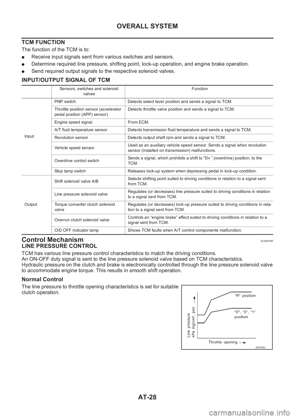
TCM has various line pressure control characteristics to match the driving conditions.
An ON-OFF duty signal is sent to the line pressure solenoid valve based on TCM characteristics.
Hydraulic pressure on the clutch and brake is electronically controlled through the line pressure solenoid valve
to accommodate engine torque. This results in smooth shift operation.
Normal Control
The line pressure to throttle opening characteristics is set for suitable
clutch operation.
Sensors, switches and solenoid
valvesFunction
InputPNP switch Detects select lever position and sends a signal to TCM.
Throttle position sensor (accelerator
pedal position (APP) sensor)Detects throttle valve position and sends a signal to TCM.
Engine speed signal From ECM.
A/T fluid temperature sensor Detects transmission fluid temperature and sends a signal to TCM.
Revolution sensor Detects output shaft rpm and sends a signal to TCM.
Vehicle speed sensorUsed as an auxiliary vehicle speed sensor. Sends a signal when revolution
sensor (installed on transmission) malfunctions.
Overdrive control switchSends a signal, which prohibits a shift to “D
4 ” (overdrive) position, to the
TCM.
Stop lamp switch Releases lock-up system when depressing pedal in lock-up condition.
OutputShift solenoid valve A/BSelects shifting point suited to driving conditions in relation to a signal sent
from TCM.
Line pressure solenoid valveRegulates (or decreases) line pressure suited to driving conditions in relation
to a signal sent from TCM.
Torque converter clutch solenoid
valveRegulates (or decreases) lock-up pressure suited to driving conditions in rela-
tion to a signal sent from TCM.
Overrun clutch solenoid valveControls an “engine brake” effect suited to driving conditions in relation to a
signal sent from TCM.
O/D OFF indicator lamp Shows TCM faults when A/T control components malfunction.
SAT003J
Page 1485 of 3189

OVERALL SYSTEM
AT-29
D
E
F
G
H
I
J
K
L
MA
B
AT
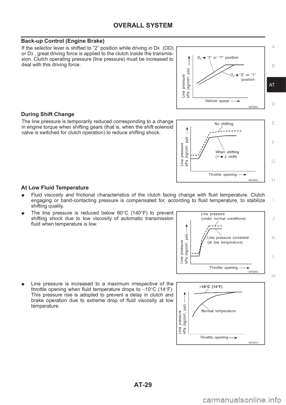
Back-up Control (Engine Brake)
If the selector lever is shifted to “2” position while driving in D4 (OD)
or D
3 , great driving force is applied to the clutch inside the transmis-
sion. Clutch operating pressure (line pressure) must be increased to
deal with this driving force.
During Shift Change
The line pressure is temporarily reduced corresponding to a change
in engine torque when shifting gears (that is, when the shift solenoid
valve is switched for clutch operation) to reduce shifting shock.
At Low Fluid Temperature
●Fluid viscosity and frictional characteristics of the clutch facing change with fluid temperature. Clutch
engaging or band-contacting pressure is compensated for, according to fluid temperature, to stabilize
shifting quality.
●The line pressure is reduced below 60°C (140°F) to prevent
shifting shock due to low viscosity of automatic transmission
fluid when temperature is low.
●Line pressure is increased to a maximum irrespective of the
throttle opening when fluid temperature drops to −10°C (14°F).
This pressure rise is adopted to prevent a delay in clutch and
brake operation due to extreme drop of fluid viscosity at low
temperature.
SAT004J
SAT005J
SAT006J
SAT007J
Page 1514 of 3189
![NISSAN ALMERA N16 2003 Electronic Owners Manual AT-58
[EURO-OBD]
TROUBLE DIAGNOSIS — INTRODUCTION
Diagnostic Worksheet
1.❏ Read the Fail-safe and listen to customer complaints.AT-57, "Infor-
mation from
Customer"
2.❏ CHECK A/T FLUIDA NISSAN ALMERA N16 2003 Electronic Owners Manual AT-58
[EURO-OBD]
TROUBLE DIAGNOSIS — INTRODUCTION
Diagnostic Worksheet
1.❏ Read the Fail-safe and listen to customer complaints.AT-57, "Infor-
mation from
Customer"
2.❏ CHECK A/T FLUIDA](/img/5/57350/w960_57350-1513.png)
AT-58
[EURO-OBD]
TROUBLE DIAGNOSIS — INTRODUCTION
Diagnostic Worksheet
1.❏ Read the Fail-safe and listen to customer complaints.AT-57, "Infor-
mation from
Customer"
2.❏ CHECK A/T FLUIDAT-63, "A/T
Fluid Check"❏ Leakage (Follow specified procedure)
❏ Fluid condition
❏ Fluid level
3.❏ Perform STALL TEST and LINE PRESSURE TEST.AT-64, "
Stall
Te s t",AT- 6 7 ,
"Line Pres-
sure Test"
❏ Stall test — Mark possible damaged components/others.
❏ Torque converter one-way clutch
❏ Reverse clutch
❏ Forward clutch
❏ Overrun clutch
❏ Forward one-way clutch❏ Low & reverse brake
❏ Low one-way clutch
❏ Engine
❏ Line pressure is low
❏ Clutches and brakes except high clutch and
brake band are OK
❏ Line Pressure test — Suspected parts:
4.❏ Perform all ROAD TEST and mark required procedures.AT-68, "
Road
Te s t"
4-
1.Check before engine is started.AT-70, "1.
CHECK
BEFORE
ENGINE IS
STARTED"
❏ SELF-DIAGNOSTIC PROCEDURE/DIAGNOSTIC TROUBLE CODE (DTC) CONFIRMATION PROCE-
DURE. — Mark detected items.
❏ PNP switch, AT- 111
.
❏ A/T fluid temperature sensor, AT- 11 7
.
❏ Vehicle speed sensor·A/T (Revolution sensor), AT-123
.
❏ Engine speed signal, AT-129
.
❏ Torque converter clutch solenoid valve, AT- 1 5 9
.
❏ Line pressure solenoid valve, AT-164
.
❏ Shift solenoid valve A, AT-171
.
❏ Shift solenoid valve B, AT-176
.
❏ Accelerator pedal position (APP) sensor, AT-181
.
❏ Overrun clutch solenoid valve, AT-187
.
❏ PNP & overdrive control switches, and throttle position sensor, AT- 2 3 7
.
❏ Batt/fluid temp sen (A/T fluid temperature sensor and TCM power source), AT-195
.
❏ Vehicle speed sensor·MTR, AT- 2 0 1
.
❏ CAN communication line, AT-192
.
❏ Control unit (RAM), control unit (ROM), AT- 2 0 5
.
❏ Control unit (EEP ROM), AT- 2 0 7
.
❏ Battery
❏ Others
4-
2.Check at idleAT-71, "
2.
CHECK AT
IDLE"❏ 1. O/D OFF Indicator Lamp Does Not Come On, AT- 2 11 .
❏ 2. Engine Cannot Be Started In “P” And “N” Position, AT- 2 1 2
.
❏ 3. In “P” Position, Vehicle Moves Forward Or Backward When Pushed, AT- 2 1 3
.
❏ 4. In “N” Position, Vehicle Moves, AT- 2 1 4
.
❏ 5. Large Shock. “N” → “R” Position, AT-215
.
❏ 6. Vehicle Does Not Creep Backward In “R” Position, AT- 2 1 6
.
❏ 7. Vehicle Does Not Creep Forward In “D”, “2” Or “1” Position, AT-219
.
Page 1515 of 3189
![NISSAN ALMERA N16 2003 Electronic Owners Manual TROUBLE DIAGNOSIS — INTRODUCTION
AT-59
[EURO-OBD]
D
E
F
G
H
I
J
K
L
MA
B
AT
4. 4-
3.Cruise testAT- 7 4 , "3.
CRUISE
TEST"
AT- 7 8 ,
"Cruise Test
— Part 1"
Part-1
❏ 8. Vehi NISSAN ALMERA N16 2003 Electronic Owners Manual TROUBLE DIAGNOSIS — INTRODUCTION
AT-59
[EURO-OBD]
D
E
F
G
H
I
J
K
L
MA
B
AT
4. 4-
3.Cruise testAT- 7 4 , "3.
CRUISE
TEST"
AT- 7 8 ,
"Cruise Test
— Part 1"
Part-1
❏ 8. Vehi](/img/5/57350/w960_57350-1514.png)
TROUBLE DIAGNOSIS — INTRODUCTION
AT-59
[EURO-OBD]
D
E
F
G
H
I
J
K
L
MA
B
AT
4. 4-
3.Cruise testAT- 7 4 , "3.
CRUISE
TEST"
AT- 7 8 ,
"Cruise Test
— Part 1"
Part-1
❏ 8. Vehicle Cannot Be Started From D
1 , AT- 2 2 1 .
❏ 9. A/T Does Not Shift: D
1→ D2 Or Does Not Kickdown: D4→ D2 , AT- 2 2 3 .
❏ 10. A/T Does Not Shift: D
2→ D3 , AT- 2 2 5 .
❏ 11. A/T Does Not Shift: D
3→ D4 , AT-227 .
❏ 12. A/T Does Not Perform Lock-up, AT- 2 3 0
.
❏ 13. A/T Does Not Hold Lock-up Condition, AT- 2 3 1
.
❏ 14. Lock-up Is Not Released, AT- 2 3 2
.
❏ 15. Engine Speed Does Not Return To Idle (Light Braking D
4→ D3 ), AT-233 .
Part-2AT- 8 1 ,
"Cruise Test
— Part 2"❏ 16. Vehicle Does Not Start From D1 , AT- 2 3 4 .
❏ 9. A/T Does Not Shift: D
1→ D2 Or Does Not Kickdown: D4→ D2 , AT- 2 2 3 .
❏ 10. A/T Does Not Shift: D
2→ D3 , AT- 2 2 5 .
❏ 11. A/T Does Not Shift: D
3→ D4 , AT-227 .
Part-3AT- 8 3 ,
"Cruise Test
— Part 3"❏ 17. A/T Does Not Shift: D4→ D3 When Overdrive Control Switch “ON” → “OFF”, AT- 2 3 5 .
❏ 15. Engine Speed Does Not Return To Idle (Light Braking D
4→ D3 ), AT-233 .
❏ 18. A/T Does Not Shift: D
3→ 22 , When Selector Lever “D” → “2” Position, AT-235 .
❏ 15. Engine Speed Does Not Return To Idle (Light Braking D
4→ D3 ), AT-233 .
❏ 19. A/T Does Not Shift: 2
2→ 11 , When Selector Lever “2” → “1” Position, AT-236 .
❏ 20. Vehicle Does Not Decelerate By Engine Brake, AT- 2 3 7
.
❏ 21. TCM Self-diagnosis Does Not Activate (PNP & Overdrive Control Switches, and Throttle Position
Sensor Circuit Checks), AT- 2 3 7
.
❏ SELF-DIAGNOSTIC PROCEDURE/DIAGNOSTIC TROUBLE CODE (DTC) CONFIRMATION PROCE-
DURE — Mark detected items.
❏ PNP switch, AT- 111
.
❏ A/T fluid temperature sensor, AT- 11 7
.
❏ Vehicle speed sensor·A/T (Revolution sensor), AT- 1 2 3
.
❏ Engine speed signal, AT- 1 2 9
.
❏ Torque converter clutch solenoid valve, AT-159
.
❏ Line pressure solenoid valve, AT-164
.
❏ Shift solenoid valve A, AT- 1 7 1
.
❏ Shift solenoid valve B, AT- 1 7 6
.
❏ Accelerator pedal position (APP) sensor, AT-181
.
❏ Overrun clutch solenoid valve, AT- 1 8 7
.
❏ PNP & overdrive control switches, and throttle position sensor, AT- 2 3 7
.
❏ A/T fluid temperature sensor and TCM power source, AT-195
.
❏ Vehicle speed sensor·MTR, AT-201
.
❏ CAN communication line, AT- 1 9 2
❏ Control unit (RAM), control unit (ROM), AT-205 .
❏ Control unit (EEP ROM), AT-207
.
❏ Battery
❏ Others
5.❏ For self-diagnosis NG items, inspect each component. Repair or replace the damaged parts.AT- 5 0 , "
Diag-
nostic Proce-
dure Without
CONSULT-II"
6.❏ Perform all ROAD TEST and re-mark required procedures.AT- 6 8 , "Road
Te s t"
7.❏ Perform DTC CONFIRMATION PROCEDURE for following MI indicating items and check out NG items.
Refer toEC-37, "
Emission-related Diagnostic Information" .EC section
❏ DTC (P0731) A/T 1st gear function, AT- 1 3 3
.
❏ DTC (P0732) A/T 2nd gear function, AT-139
.
❏ DTC (P0733) A/T 3rd gear function, AT- 1 4 5
.
❏ DTC (P0734) A/T 4th gear function, AT- 1 5 1
.
Page 1518 of 3189
![NISSAN ALMERA N16 2003 Electronic Owners Manual AT-62
[EURO-OBD]
TROUBLE DIAGNOSIS — INTRODUCTION
*1:AT-57, "Information from Customer"*2:AT-58, "Diagnostic Worksheet"*3:AT-7, "Service Notice or Precau-
tions"
*4:AT-63, &# NISSAN ALMERA N16 2003 Electronic Owners Manual AT-62
[EURO-OBD]
TROUBLE DIAGNOSIS — INTRODUCTION
*1:AT-57, "Information from Customer"*2:AT-58, "Diagnostic Worksheet"*3:AT-7, "Service Notice or Precau-
tions"
*4:AT-63, &#](/img/5/57350/w960_57350-1517.png)
AT-62
[EURO-OBD]
TROUBLE DIAGNOSIS — INTRODUCTION
*1:AT-57, "Information from Customer"*2:AT-58, "Diagnostic Worksheet"*3:AT-7, "Service Notice or Precau-
tions"
*4:AT-63, "A/T Fluid Check"*5:AT-64, "Stall Test" and AT- 6 7 , "Line Pressure
Te s t"
*6:AT- 6 8 , "Road Test"
*7:AT-41, "CONSULT-II"*8:AT-37, "ON BOARD DIAGNOSTIC SYSTEM
DESCRIPTION"
*9:AT- 5 0 , "Diagnostic Procedure
Without CONSULT-II"
*10:AT- 111 , "DTC P0705 PARK/NEU-
TRAL POSITION (PNP) SWITCH"
*11:AT-123, "DTC P0720 VEHICLE SPEED
SENSOR A/T (REVOLUTION SENSOR)"
and AT- 2 0 5 , "DTC CONTROL UNIT (RAM),
CONTROL UNIT (ROM)" to AT-207, "DTC
CONTROL UNIT (EEP ROM)"
*12:AT- 2 11 , "1. O/D OFF Indicator
Lamp Does Not Come On"
*13:AT-237, "20. Vehicle Does Not
Decelerate By Engine Brake"
*14:AT-86, "Symptom Chart"*15:AT- 3 9 , "HOW TO ERASE DTC"
*16:AT- 111 , "DTC P0705 PARK/NEU-
TRAL POSITION (PNP) SWITCH"
*17:AT-123, "DTC P0720 VEHICLE SPEED
SENSOR A/T (REVOLUTION SENSOR)"
and AT- 2 0 5 , "DTC CONTROL UNIT (RAM),
CONTROL UNIT (ROM)" to AT-207, "DTC
CONTROL UNIT (EEP ROM)"
*18:EC-429, "Emission-related Diag-
nostic Information"
Page 1519 of 3189
![NISSAN ALMERA N16 2003 Electronic Owners Manual TROUBLE DIAGNOSIS — BASIC INSPECTION
AT-63
[EURO-OBD]
D
E
F
G
H
I
J
K
L
MA
B
AT
TROUBLE DIAGNOSIS — BASIC INSPECTIONPFP:00000
A/T Fluid CheckECS007NW
FLUID LEAKAGE CHECK
1. Clean area suspected of NISSAN ALMERA N16 2003 Electronic Owners Manual TROUBLE DIAGNOSIS — BASIC INSPECTION
AT-63
[EURO-OBD]
D
E
F
G
H
I
J
K
L
MA
B
AT
TROUBLE DIAGNOSIS — BASIC INSPECTIONPFP:00000
A/T Fluid CheckECS007NW
FLUID LEAKAGE CHECK
1. Clean area suspected of](/img/5/57350/w960_57350-1518.png)
TROUBLE DIAGNOSIS — BASIC INSPECTION
AT-63
[EURO-OBD]
D
E
F
G
H
I
J
K
L
MA
B
AT
TROUBLE DIAGNOSIS — BASIC INSPECTIONPFP:00000
A/T Fluid CheckECS007NW
FLUID LEAKAGE CHECK
1. Clean area suspected of leaking. — for example, mating surface
of converter housing and transmission case.
2. Start engine, apply foot brake, place selector lever in “D” posi-
tion and wait a few minutes.
3. Stop engine.
4. Check for fluid leakage.
FLUID CONDITION CHECK
FLUID LEVEL CHECK
Refer to AT-13, "Checking A/T Fluid" .
SAT767B
SAT288G
Fluid color Suspected problem
Dark or black with burned odor Wear of frictional material
Milky pink Water contamination — Road water
entering through filler tube or breather
Varnished fluid, light to dark brown and
tackyOxidation — Over or under filling, —
Overheating
SAT638A
Page 1520 of 3189
![NISSAN ALMERA N16 2003 Electronic Owners Manual AT-64
[EURO-OBD]
TROUBLE DIAGNOSIS — BASIC INSPECTION
Stall Test
ECS007NX
STALL TEST PROCEDURE
1. Check A/T fluid and engine oil levels. If necessary, add.
2. Drive vehicle for approx. 10 minut NISSAN ALMERA N16 2003 Electronic Owners Manual AT-64
[EURO-OBD]
TROUBLE DIAGNOSIS — BASIC INSPECTION
Stall Test
ECS007NX
STALL TEST PROCEDURE
1. Check A/T fluid and engine oil levels. If necessary, add.
2. Drive vehicle for approx. 10 minut](/img/5/57350/w960_57350-1519.png)
AT-64
[EURO-OBD]
TROUBLE DIAGNOSIS — BASIC INSPECTION
Stall Test
ECS007NX
STALL TEST PROCEDURE
1. Check A/T fluid and engine oil levels. If necessary, add.
2. Drive vehicle for approx. 10 minutes or until fluid and oil reach
operating temperature.
3. Set parking brake and block wheels.
4. Install a tachometer where it can be seen by driver during test.
●It is good practice to mark the point of specified engine
rpm on indicator.
5. Start engine, apply foot brake, and place selector lever in D
position.
6. Accelerate to wide open throttle gradually while applying foot
brake.
7. Quickly note the engine stall revolution and immediately release
throttle.
●During test, never hold throttle wide open for more than 5
seconds.
Stall revolution:
8. Move selector lever to “N” position.
9. Cool off ATF.
●Run engine at idle for at least one minute.
10. Repeat steps 5 through 9 with selector lever in “2”, “1” and “R”
positions.ATF operating temperature:
50 - 80°C (122 - 176°F)
SAT647B
SAT513G
SAT514G
QG18DE 2,300 - 2,750 rpm
SAT771B
Page 1521 of 3189
![NISSAN ALMERA N16 2003 Electronic Owners Manual TROUBLE DIAGNOSIS — BASIC INSPECTION
AT-65
[EURO-OBD]
D
E
F
G
H
I
J
K
L
MA
B
AT
JUDGEMENT OF STALL TEST
The test result and possible damaged components relating to each result are shown in the illus NISSAN ALMERA N16 2003 Electronic Owners Manual TROUBLE DIAGNOSIS — BASIC INSPECTION
AT-65
[EURO-OBD]
D
E
F
G
H
I
J
K
L
MA
B
AT
JUDGEMENT OF STALL TEST
The test result and possible damaged components relating to each result are shown in the illus](/img/5/57350/w960_57350-1520.png)
TROUBLE DIAGNOSIS — BASIC INSPECTION
AT-65
[EURO-OBD]
D
E
F
G
H
I
J
K
L
MA
B
AT
JUDGEMENT OF STALL TEST
The test result and possible damaged components relating to each result are shown in the illustrations on next
page.
In order to pinpoint the possible damaged components, follow the WORK FLOW shown in AT-60, "
Work Flow"
(EURO-OBD).
NOTE:
Stall revolution is too high in “D”, “2” or “1” position:
●Slippage occurs in 1st gear but not in 2nd and 3rd gears...... Low one-way clutch slippage
●Slippage occurs in the following gears:
1st through 3rd gears in “D” position and engine brake functions with overdrive control switch set to
“OFF”.
1st and 2nd gears in “2” position and engine brake functions with accelerator pedal released (fully closed
throttle)...... Forward clutch or forward one-way clutch slippage
Stall revolution is too high in R position:
●Engine brake does not function in “1” position...... Low & reverse brake slippage
●Engine brake functions in “1” position...... Reverse clutch slippage
Stall revolution within specifications:
●Vehicle does not achieve speed of more than 80 km/h (50 MPH)...... One-way clutch seizure in torque
converter housing
CAUTION:
Be careful since automatic fluid temperature increases abnormally.
●Slippage occurs in 3rd and 4th gears in “D” position...... High clutch slippage
●Slippage occurs in 2nd and 4th gear in “D” position...... Brake band slippage
●Engine brake does not function in 2nd and 3rd gears in “D” position, 2nd gear in “2” position, and 1st gear
in “1” position with overdrive control switch set to “OFF”.
Stall revolution less than specifications:
●Poor acceleration during starts...... One-way clutch seizure in torque converter