ABS NISSAN ALMERA N16 2003 Electronic Repair Manual
[x] Cancel search | Manufacturer: NISSAN, Model Year: 2003, Model line: ALMERA N16, Model: NISSAN ALMERA N16 2003Pages: 3189, PDF Size: 54.76 MB
Page 38 of 3189
NJGI0007
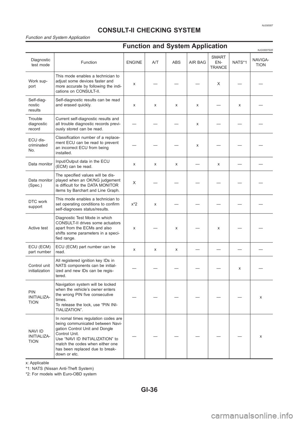
Function and System ApplicationNJGI0007S05
Diagnostic
test modeFunction ENGINE A/T ABS AIR BAGSMART
EN-
TRANCENATS*1NAVIGA-
TION
Work sup-
portThis mode enables a technician to
adjust some devices faster and
more accurate by following the indi-
cations on CONSULT-II.x ———X——
Self-diag-
nostic
resultsSelf-diagnostic results can be read
anderasedquickly. x x x x—x—
Trouble
diagnostic
recordCurrent self-diagnostic results and
all trouble diagnostic records previ-
ously stored can be read.——— x ———
ECU dis-
criminated
No.Classification number of a replace-
ment ECU can be read to prevent
an incorrect ECU from being
installed.——— x ———
Data monitorInput/Output data in the ECU
(ECM) can be read.x x x—x——
Data monitor
(Spec.)The specified values will be dis-
played when an OK/NG judgement
is difficult for the DATA MONITOR
items by Barchart and Line Graph.X ——————
DTC work
supportThis mode enables a technician to
set operating conditions to confirm
self-diagnoses status/results.x*2x —————
Active testDiagnostic Test Mode in which
CONSULT-II drives some actuators
apart from the ECMs and also
shifts some parameters in a speci-
fied range.x—x—x——
ECU (ECM)
part numberECU (ECM) part number can be
read.x x x ————
Control unit
initializationAll registered ignition key IDs in
NATS components can be initial-
ized and new IDs can be regis-
tered.————— x —
PIN
INITIALIZA-
TIONNavigation system will be locked
when the vehicle’s owner enters
the wrong PIN five consecutive
times.
To release the lock, use “PIN INI-
TIALIZATION”.—————— x
NAVI ID
INITIALIZA-
TIONIn nomal times regulation codes are
being communicated between Navi-
gation Control Unit and Dongle
Control Unit.
Use “NAVI ID INITIALIZATION” to
match the codes when either one
has been replaced due to break-
down or etc.—————— x
x: Applicable
*1: NATS (Nissan Anti-Theft System)
*2: For models with Euro-OBD system
CONSULT-II CHECKING SYSTEM
Function and System Application
GI-36
Page 55 of 3189
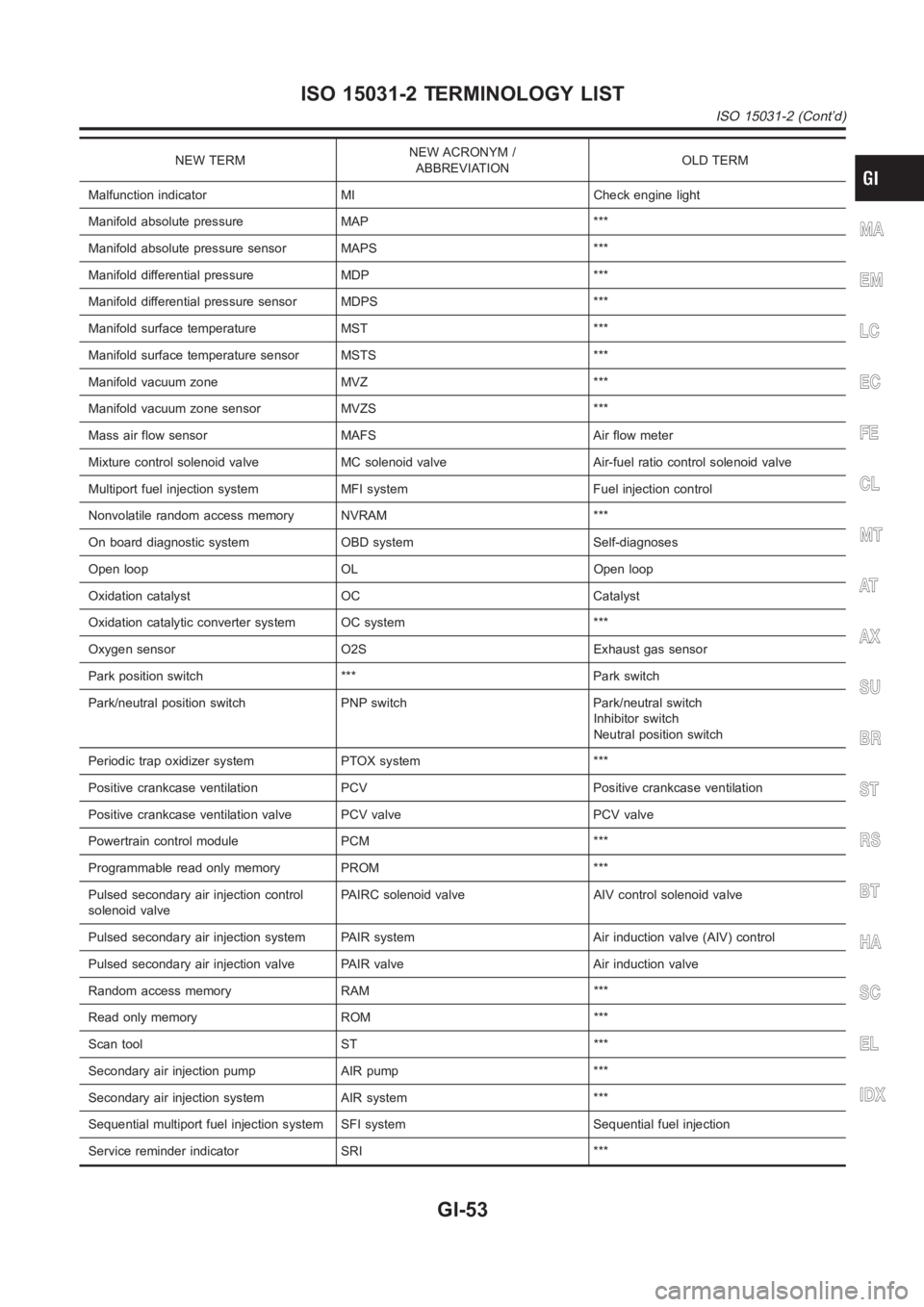
NEW TERMNEW ACRONYM /
ABBREVIATIONOLD TERM
Malfunction indicator MI Check engine light
Manifold absolute pressure MAP ***
Manifold absolute pressure sensor MAPS ***
Manifold differential pressure MDP ***
Manifold differential pressure sensor MDPS ***
Manifold surface temperature MST ***
Manifold surface temperature sensor MSTS ***
Manifold vacuum zone MVZ ***
Manifold vacuum zone sensor MVZS ***
Mass air flow sensor MAFS Air flow meter
Mixture control solenoid valve MC solenoid valve Air-fuel ratio control solenoid valve
Multiport fuel injection system MFI system Fuel injection control
Nonvolatile random access memory NVRAM ***
On board diagnostic system OBD system Self-diagnoses
Open loop OL Open loop
Oxidation catalyst OC Catalyst
Oxidation catalytic converter system OC system ***
Oxygen sensor O2S Exhaust gas sensor
Park position switch *** Park switch
Park/neutral position switch PNP switch Park/neutral switch
Inhibitor switch
Neutral position switch
Periodic trap oxidizer system PTOX system ***
Positive crankcase ventilation PCV Positive crankcase ventilation
Positive crankcase ventilation valve PCV valve PCV valve
Powertrain control module PCM ***
Programmable read only memory PROM ***
Pulsed secondary air injection control
solenoid valvePAIRC solenoid valve AIV control solenoid valve
Pulsed secondary air injection system PAIR system Air induction valve (AIV) control
Pulsed secondary air injection valve PAIR valve Air induction valve
Random access memory RAM ***
Read only memory ROM ***
Scan tool ST ***
Secondary air injection pump AIR pump ***
Secondary air injection system AIR system ***
Sequential multiport fuel injection system SFI system Sequential fuel injection
Service reminder indicator SRI ***
MA
EM
LC
EC
FE
CL
MT
AT
AX
SU
BR
ST
RS
BT
HA
SC
EL
IDX
ISO 15031-2 TERMINOLOGY LIST
ISO 15031-2 (Cont’d)
GI-53
Page 139 of 3189
![NISSAN ALMERA N16 2003 Electronic Repair Manual CYLINDER HEAD
EM-61
[QG]
C
D
E
F
G
H
I
J
K
L
MA
EM
2. Remove valve collet.
●Compress valve spring with valve spring compressor (special
service tool). Remove valve collet with magnet driver.
3. Remo NISSAN ALMERA N16 2003 Electronic Repair Manual CYLINDER HEAD
EM-61
[QG]
C
D
E
F
G
H
I
J
K
L
MA
EM
2. Remove valve collet.
●Compress valve spring with valve spring compressor (special
service tool). Remove valve collet with magnet driver.
3. Remo](/img/5/57350/w960_57350-138.png)
CYLINDER HEAD
EM-61
[QG]
C
D
E
F
G
H
I
J
K
L
MA
EM
2. Remove valve collet.
●Compress valve spring with valve spring compressor (special
service tool). Remove valve collet with magnet driver.
3. Remove valve spring retainer and valve spring.
4. Push valve stem to combustion chamber side, and remove
valve.
●Inspect valve guide clearance before removal. Refer to EM-
63, "VALVE GUIDE CLEARANCE" .
●Confirm installation point.
5. Remove valve oil seal with valve oil seal puller (special service
tool).
6. Remove valve spring seat.
7. When valve seat must be replaced, refer to EM-64, "
VA LV E
SEAT REPLACEMENT" .
8. When valve guide must be replaced, refer to EM-63, "
VA LV E
GUIDE REPLACEMENT" .
9. Remove spark plug with spark plug wrench (commercial service
tool).
10. Remove engine coolant temperature sensor.
CAUTION:
Do not shock it.
11. Remove spark plug tube, as necessary.
●Using a pair of pliers, pull spark plug tube out of cylinder head.
CAUTION:
●Take care not to damage cylinder head.
●Once removed, a spark plug tube will be deformed and cannot be reused. Do not remove it
unless absolutely necessary.
ASSEMBLY
1. Install valve guide. Refer to EM-63, "VALVE GUIDE REPLACEMENT" .
2. Install valve seat. Refer to EM-64, "
VALVE SEAT REPLACEMENT" .
3. Install valve oil seal.
●Install with valve oil seal drift (special service tool) to match
dimension in illustration.
4. Install valve spring seat.
5. Install valve.
●Install larger diameter to intake side.
6. Install valve spring.
7. Install valve spring retainer.
PBIC1015E
SEM909F
PBIC0576E
Page 248 of 3189
crankshaft position sensor (TDC sensor) from the assem-
bly.
Always pay extra attention not to damage edge of crank-
shaft position sensor (TDC sensor) or ring gear teeth.
REMOVALNJEM0069S011. Remove engine undercover, and hood for hoisting.
2. Drain coolant from both cylinder block and radiator. Refer to
LC-43, “Changing Engine Coolant”.
3. Remove the following parts:
Battery
RH and LH front wheels
RH and LH splash covers (combined with undercover)
Auxiliary belts
Alternator
Alternator brackets
Radiator and cooling fan
Engine cover
Air ducts and air cleaner case
LH side of engine room:
4. Disconnect all harnesses and grounds that are connected to
components on vehicle.
5. Disconnect vacuum hose on vacuum pump side.
6. Disconnect fuel feed and fuel return hoses on engine side.
Immediately put blind plugs into the openings to prevent
fuel from flowing out.
7. Disconnect heater hose. Plug opening of hose to prevent cool-
ant from flowing out.
RH side of engine room:
8. Remove air conditioner compressor from brackets and move
it toward vehicle side. Secure compressor on vehicle side with
rope.
Vehicle underside:
9. Remove exhaust front tube.
10. Disconnect two hoses from power steering pump and plug to
stop fluid.
11. Remove M/T control rod and support rod.
12. Remove ABS wheel sensor, and temporarily hang brake cali-
per with rope on vehicle side.
13. Remove RH and LH drive shafts.
YEM024
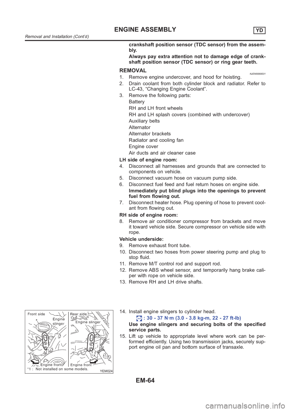
14. Install engine slingers to cylinder head.
: 30 - 37 N·m (3.0 - 3.8 kg-m, 22 - 27 ft-lb)
Use engine slingers and securing bolts of the specified
service parts.
15. Lift up vehicle to appropriate level where work can be per-
formed efficiently. Using two transmission jacks, securely sup-
port engine oil pan and bottom surface of transaxle.
ENGINE ASSEMBLYYD
Removal and Installation (Cont’d)
EM-64
Page 297 of 3189
Thermostat
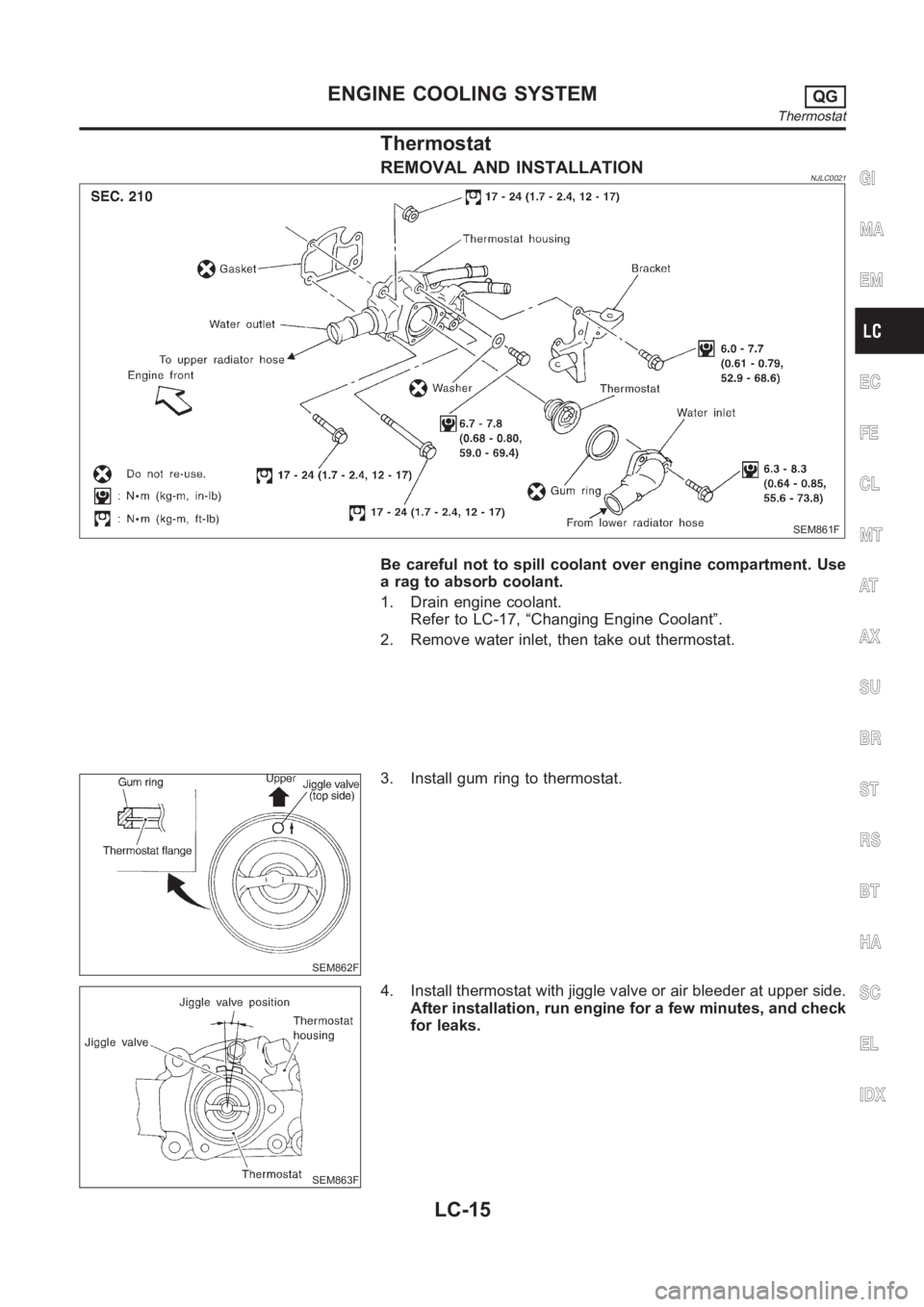
REMOVAL AND INSTALLATIONNJLC0021
SEM861F
Be careful not to spill coolant over engine compartment. Use
a rag to absorb coolant.
1. Drain engine coolant.
Refer to LC-17, “Changing Engine Coolant”.
2. Remove water inlet, then take out thermostat.
SEM862F
3. Install gum ring to thermostat.
SEM863F
4. Install thermostat with jiggle valve or air bleeder at upper side.
After installation, run engine for a few minutes, and check
for leaks.
GI
MA
EM
EC
FE
CL
MT
AT
AX
SU
BR
ST
RS
BT
HA
SC
EL
IDX
ENGINE COOLING SYSTEMQG
Thermostat
LC-15
Page 322 of 3189
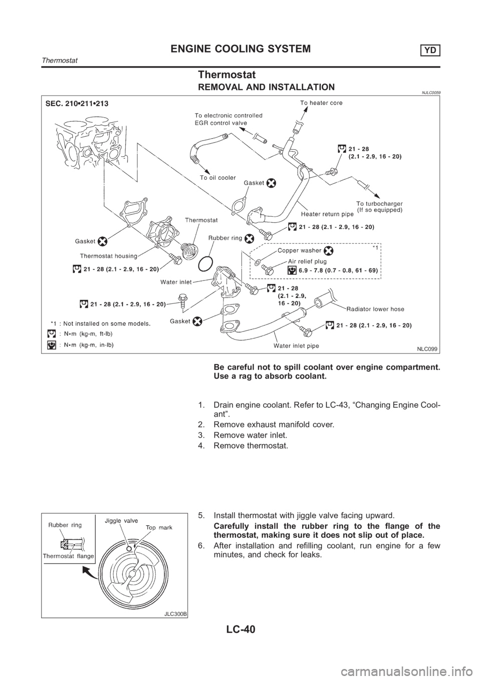
Thermostat
REMOVAL AND INSTALLATIONNJLC0059
NLC099
Be careful not to spill coolant over engine compartment.
Use a rag to absorb coolant.
1. Drain engine coolant. Refer to LC-43, “Changing Engine Cool-
ant”.
2. Remove exhaust manifold cover.
3. Remove water inlet.
4. Remove thermostat.
JLC300B
5. Install thermostat with jiggle valve facing upward.
Carefully install the rubber ring to the flange of the
thermostat, making sure it does not slip out of place.
6. After installation and refilling coolant, run engine for a few
minutes, and check for leaks.
ENGINE COOLING SYSTEMYD
Thermostat
LC-40
Page 357 of 3189
![NISSAN ALMERA N16 2003 Electronic Repair Manual ENGINE CONTROL SYSTEM
EC-27
[QG (WITH EURO-OBD)]
C
D
E
F
G
H
I
J
K
L
MA
EC
Fuel Cut Control (at No Load and High Engine Speed)EBS00K38
INPUT/OUTPUT SIGNAL CHART
*1: This signal is sent to the ECM thro NISSAN ALMERA N16 2003 Electronic Repair Manual ENGINE CONTROL SYSTEM
EC-27
[QG (WITH EURO-OBD)]
C
D
E
F
G
H
I
J
K
L
MA
EC
Fuel Cut Control (at No Load and High Engine Speed)EBS00K38
INPUT/OUTPUT SIGNAL CHART
*1: This signal is sent to the ECM thro](/img/5/57350/w960_57350-356.png)
ENGINE CONTROL SYSTEM
EC-27
[QG (WITH EURO-OBD)]
C
D
E
F
G
H
I
J
K
L
MA
EC
Fuel Cut Control (at No Load and High Engine Speed)EBS00K38
INPUT/OUTPUT SIGNAL CHART
*1: This signal is sent to the ECM through CAN communication line.
SYSTEM DESCRIPTION
If the engine speed is above 3,950 rpm with no load (for example, in neutral and engine speed over 3,950
rpm) fuel will be cut off after some time. The exact time when the fuel is cut off varies based on engine speed.
Fuel cut will operate until the engine speed reaches 1,500 rpm, then fuel cut is cancelled.
NOTE:
This function is different from deceleration control listed under “Multiport Fuel Injection (MFI) System”, EC-23
.
CAN CommunicationEBS00K39
SYSTEM DESCRIPTION
CAN (Controller Area Network) is a serial communication line for real time application. It is an on-vehicle mul-
tiplex communication line with high data communication speed and excellent error detection ability. Many elec-
tronic control units are equipped onto a vehicle, and each control unit shares information and links with other
control units during operation (not independent). In CAN communication, control units are connected with 2
communication lines (CAN H line, CAN L line) allowing a high rate of information transmission with less wiring.
Each control unit transmits/receives data but selectively reads required data only.
CAN COMMUNICATION UNIT
×:ApplicableSensor Input Signal to ECM ECM Function Actuator
Park/neutral position (PNP) switch Neutral position
Fuel cut control Fuel injectors Throttle position sensor Throttle position
Accelerator pedal position sensor Accelerator pedal position
Engine coolant temperature sensor Engine coolant temperature
Crankshaft position sensor (POS)
Camshaft position sensor (PHASE)Engine speed
Vehicle speed signal
*1Vehicle speed
Body type Sedan/ 5DH/B/ 3DH/B
Axle2WD
Engine QG18DE QG15DE/QG18DE
Transmission A/T M/T
Brake controlABS
CAN communication unit
ECM××
TCM×
Smart entrance control unit××
Data link connector××
Combination meter××
CAN communication type EC-28, "
Type 1"EC-29, "Ty p e 2"
Page 587 of 3189
![NISSAN ALMERA N16 2003 Electronic Repair Manual DTC P0500 VSS
EC-257
[QG (WITH EURO-OBD)]
C
D
E
F
G
H
I
J
K
L
MA
EC
DTC P0500 VSSPFP:32702
DescriptionEBS00K8V
NOTE:
If DTC P0500 is displayed with DTC U1000 or U1001, first perform the trouble diagno NISSAN ALMERA N16 2003 Electronic Repair Manual DTC P0500 VSS
EC-257
[QG (WITH EURO-OBD)]
C
D
E
F
G
H
I
J
K
L
MA
EC
DTC P0500 VSSPFP:32702
DescriptionEBS00K8V
NOTE:
If DTC P0500 is displayed with DTC U1000 or U1001, first perform the trouble diagno](/img/5/57350/w960_57350-586.png)
DTC P0500 VSS
EC-257
[QG (WITH EURO-OBD)]
C
D
E
F
G
H
I
J
K
L
MA
EC
DTC P0500 VSSPFP:32702
DescriptionEBS00K8V
NOTE:
If DTC P0500 is displayed with DTC U1000 or U1001, first perform the trouble diagnosis for DTC U1000,
U1001. Refer to EC-116, "
DTC U1000, U1001 CAN COMMUNICATION LINE" .
The vehicle speed signal is sent from vehicle speed sensor (models without ABS) or ABS actuator and electric
unit (control unit) (models with ABS) to combination meter. The combination meter then sends a signal to the
ECM through CAN communication line.
On Board Diagnosis LogicEBS00K8W
DTC Confirmation ProcedureEBS00K8X
CAUTION:
Always drive vehicle at a safe speed.
NOTE:
If “DTC Confirmation Procedure” has been previously conducted, always turn ignition switch “OFF” and wait at
least 10 seconds before conducting the next test.
TESTING CONDITION:
Steps 1 and 2 may be conducted with the drive wheels lifted in the shop or by driving the vehicle. If a
road test is expected to be easier, it is unnecessary to lift the vehicle.
WITH CONSULT-II
1. Start engine.
2. Read “VHCL SPEED SE” in “DATA MONITOR” mode with CONSULT-II. The vehicle speed on CONSULT-
II should exceed 10 km/h (6 MPH) when rotating wheels with suitable gear position.
If NG, go to EC-259, "
Diagnostic Procedure" .
If OK, go to following step.
3. Select “DATA MONITOR” mode with CONSULT-II.
4. Warm engine up to normal operating temperature.
5. Maintain the following conditions for at least 60 consecutive sec-
onds.
6. If 1st trip DTC is detected, go to EC-259, "
Diagnostic Procedure" .
DTC No. Trouble diagnosis name DTC detecting condition Possible cause
P0500
0500Vehicle speed sensorThe almost 0 km/h (0 MPH) signal from
vehicle speed sensor is sent to ECM
even when vehicle is being driven.
●Harness or connectors
(The vehicle speed sensor circuit is open or
shorted)
●Harness or connectors
(The CAN communication line is open or
shorted.)
●Vehicle speed sensor (models without ABS)
●ABS actuator and electric unit (control unit)
(models with ABS)
●Combination meter
ENG SPEED More than 2,400 rpm (QG15DE models)
More then 2,100 rpm (QG18DE A/T models)
More then 2,700 rpm (QG18DE M/T models)
COOLAN TEMP/S More than 70°C (158°F)
B/FUEL SCHDL More than 4.6 msec (QG15DE models)
More than 5.2 msec (QG18DE A/T models)
More than 4.3 msec (QG18DE M/T models
Selector lever Suitable position
PW/ST SIGNAL OFF
SEF196Y
Page 589 of 3189
![NISSAN ALMERA N16 2003 Electronic Repair Manual DTC P0500 VSS
EC-259
[QG (WITH EURO-OBD)]
C
D
E
F
G
H
I
J
K
L
MA
EC
WITH GST
1. Lift up drive wheels.
2. Start engine.
3. Read vehicle speed signal in “MODE 1” with GST.
The vehicle speed signal NISSAN ALMERA N16 2003 Electronic Repair Manual DTC P0500 VSS
EC-259
[QG (WITH EURO-OBD)]
C
D
E
F
G
H
I
J
K
L
MA
EC
WITH GST
1. Lift up drive wheels.
2. Start engine.
3. Read vehicle speed signal in “MODE 1” with GST.
The vehicle speed signal](/img/5/57350/w960_57350-588.png)
DTC P0500 VSS
EC-259
[QG (WITH EURO-OBD)]
C
D
E
F
G
H
I
J
K
L
MA
EC
WITH GST
1. Lift up drive wheels.
2. Start engine.
3. Read vehicle speed signal in “MODE 1” with GST.
The vehicle speed signal on GST should be able to exceed 10 km/h (6 MPH) when rotating wheels with
suitable gear position.
4. If NG, go to EC-259, "
Diagnostic Procedure" .
Diagnostic ProcedureEBS00K8Z
1.CHECK DTC WITH VEHICLE SPEED SONSOR (MODELS WITHOUT ABS) OR ABS ACTUATOR AND
ELECTRIC UNIT (CONTROL UNIT) (MODELS WITH ABS)
Refer to EL-123 (models without ABS) or EL-124 (models with ABS).
OK or NG
OK >> GO TO 2.
NG >> Repair or replace.
2.CHECK COMBINATION METER
Check combination meter function.
Refer to EL-112.
>>INSPECTION END
Page 751 of 3189
![NISSAN ALMERA N16 2003 Electronic Repair Manual ENGINE CONTROL SYSTEM
EC-421
[QG (WITHOUT EURO-OBD)]
C
D
E
F
G
H
I
J
K
L
MA
EC
Fuel Cut Control (at No Load and High Engine Speed)EBS00KEF
INPUT/OUTPUT SIGNAL CHART
*1: This signal is sent to the ECM NISSAN ALMERA N16 2003 Electronic Repair Manual ENGINE CONTROL SYSTEM
EC-421
[QG (WITHOUT EURO-OBD)]
C
D
E
F
G
H
I
J
K
L
MA
EC
Fuel Cut Control (at No Load and High Engine Speed)EBS00KEF
INPUT/OUTPUT SIGNAL CHART
*1: This signal is sent to the ECM](/img/5/57350/w960_57350-750.png)
ENGINE CONTROL SYSTEM
EC-421
[QG (WITHOUT EURO-OBD)]
C
D
E
F
G
H
I
J
K
L
MA
EC
Fuel Cut Control (at No Load and High Engine Speed)EBS00KEF
INPUT/OUTPUT SIGNAL CHART
*1: This signal is sent to the ECM through CAN communication line.
SYSTEM DESCRIPTION
If the engine speed is above 3,950 rpm with no load (for example, in neutral and engine speed over 3,950
rpm) fuel will be cut off after some time. The exact time when the fuel is cut off varies based on engine speed.
Fuel cut will operate until the engine speed reaches 1,500 rpm, then fuel cut is cancelled.
NOTE:
This function is different from deceleration control listed under “Multiport Fuel Injection (MFI) System”, EC-417
.
CAN CommunicationEBS00KEG
SYSTEM DESCRIPTION
CAN (Controller Area Network) is a serial communication line for real time application. It is an on-vehicle mul-
tiplex communication line with high data communication speed and excellent error detection ability. Many elec-
tronic control units are equipped onto a vehicle, and each control unit shares information and links with other
control units during operation (not independent). In CAN communication, control units are connected with 2
communication lines (CAN H line, CAN L line) allowing a high rate of information transmission with less wiring.
Each control unit transmits/receives data but selectively reads required data only.
CAN COMMUNICATION UNIT
×:ApplicableSensor Input Signal to ECM ECM function Actuator
Park/neutral position (PNP) switch Neutral position
Fuel cut control Fuel injectors Throttle position sensor Throttle position
Accelerator pedal position sensor Accelerator pedal position
Engine coolant temperature sensor Engine coolant temperature
Crankshaft position sensor (POS)
Camshaft position sensor (PHASE)Engine speed
Vehicle speed signal
*1Vehicle speed
Body type Sedan/ 5DH/B/ 3DH/B
Axle2WD
Engine QG18DE QG15DE/QG18DE
Transmission A/T M/T
Brake controlABS
CAN communication unit
ECM××
TCM×
Data link connector××
Smart entrance control unit××
Combination meter××
CAN communication type EC-422, "
Ty p e 1"EC-423, "Type 2"