k9k NISSAN ALMERA N16 2003 Electronic Owner's Manual
[x] Cancel search | Manufacturer: NISSAN, Model Year: 2003, Model line: ALMERA N16, Model: NISSAN ALMERA N16 2003Pages: 3189, PDF Size: 54.76 MB
Page 2493 of 3189
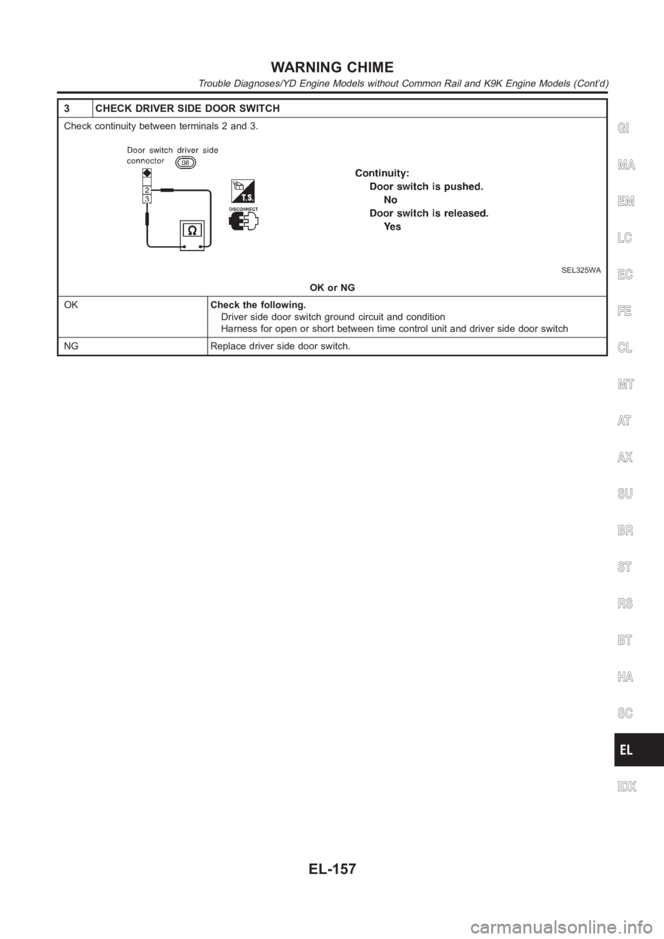
3 CHECK DRIVER SIDE DOOR SWITCH
Check continuity between terminals 2 and 3.
SEL325WA
OK or NG
OKCheck the following.
Driver side door switch ground circuit and condition
Harness for open or short between time control unit and driver side door switch
NG Replace driver side door switch.
GI
MA
EM
LC
EC
FE
CL
MT
AT
AX
SU
BR
ST
RS
BT
HA
SC
IDX
WARNING CHIME
Trouble Diagnoses/YD Engine Models without Common Rail and K9K Engine Models (Cont’d)
EL-157
Page 2510 of 3189
System Description/YD Engine Models without
Common Rail and K9K Engine Models
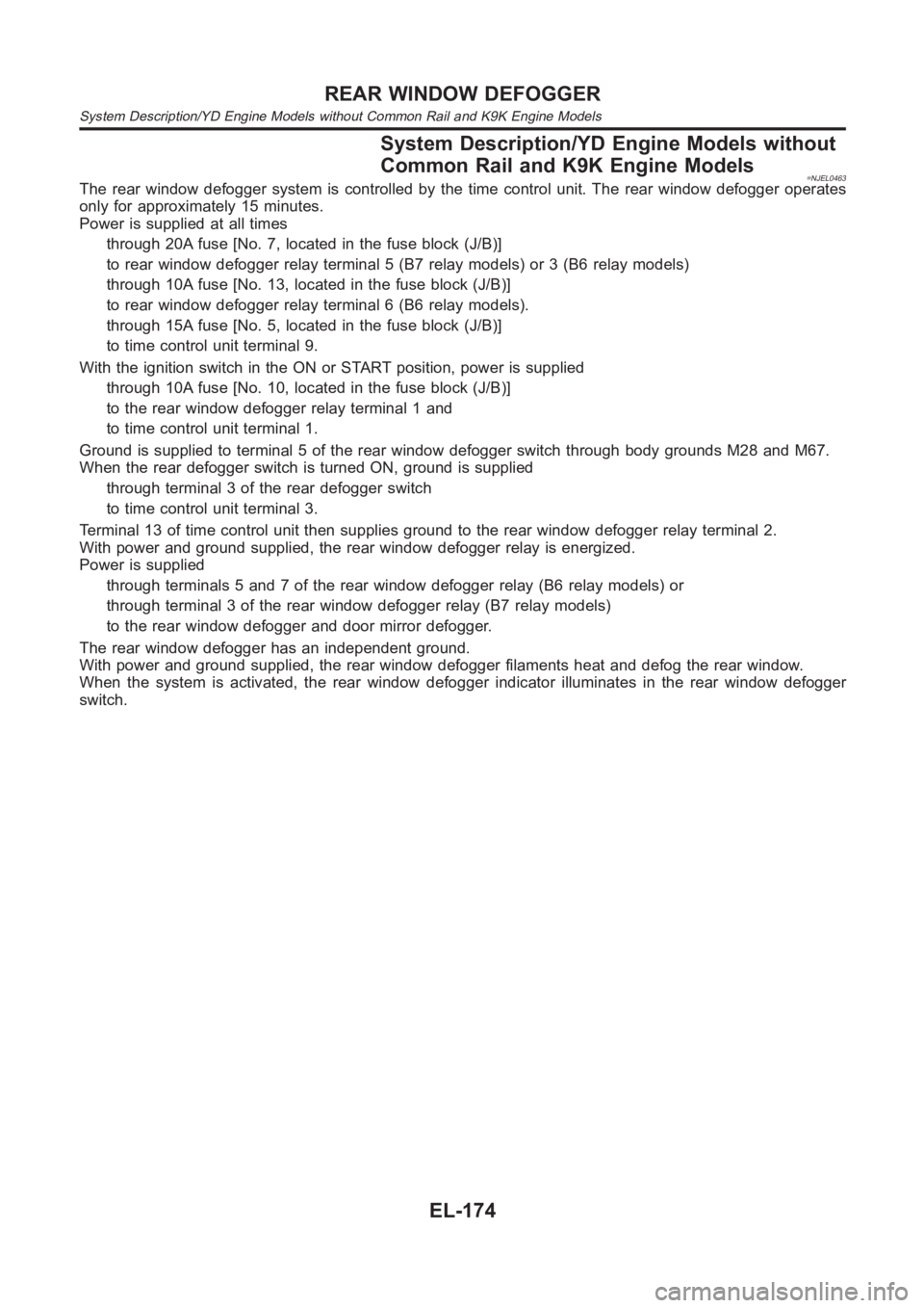
=NJEL0463The rear window defogger system is controlled by the time control unit. Therear window defogger operates
only for approximately 15 minutes.
Power is supplied at all times
through 20A fuse [No. 7, located in the fuse block (J/B)]
to rear window defogger relay terminal 5 (B7 relay models) or 3 (B6 relay models)
through 10A fuse [No. 13, located in the fuse block (J/B)]
to rear window defogger relay terminal 6 (B6 relay models).
through 15A fuse [No. 5, located in the fuse block (J/B)]
to time control unit terminal 9.
With the ignition switch in the ON or START position, power is supplied
through 10A fuse [No. 10, located in the fuse block (J/B)]
to the rear window defogger relay terminal 1 and
to time control unit terminal 1.
Ground is supplied to terminal 5 of the rear window defogger switch throughbody grounds M28 and M67.
When the rear defogger switch is turned ON, ground is supplied
through terminal 3 of the rear defogger switch
to time control unit terminal 3.
Terminal 13 of time control unit then supplies ground to the rear window defogger relay terminal 2.
With power and ground supplied, the rear window defogger relay is energized.
Power is supplied
through terminals 5 and 7 of the rear window defogger relay (B6 relay models)or
through terminal 3 of the rear window defogger relay (B7 relay models)
to the rear window defogger and door mirror defogger.
The rear window defogger has an independent ground.
With power and ground supplied, the rear window defogger filaments heat and defog the rear window.
When the system is activated, the rear window defogger indicator illuminates in the rear window defogger
switch.
REAR WINDOW DEFOGGER
System Description/YD Engine Models without Common Rail and K9K Engine Models
EL-174
Page 2522 of 3189
Trouble Diagnoses/YD Engine Models without
Common Rail and K9K Engine Models
=NJEL0465DIAGNOSTIC PROCEDURENJEL0465S01SYMPTOM: Rear window defogger does not activate, or does
not go off after activating.
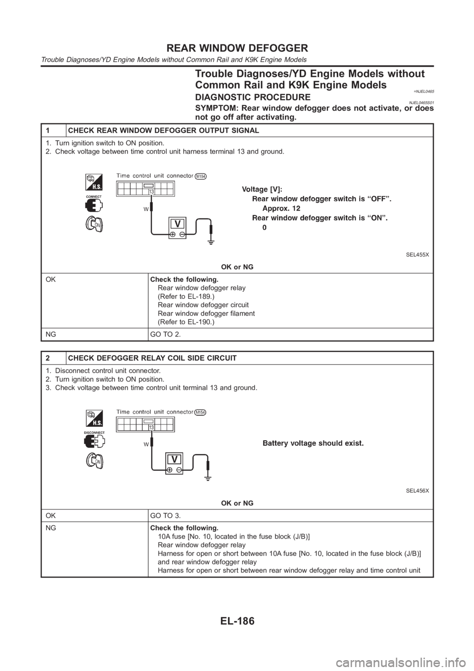
1 CHECK REAR WINDOW DEFOGGER OUTPUT SIGNAL
1. Turn ignition switch to ON position.
2. Check voltage between time control unit harness terminal 13 and ground.
SEL455X
OK or NG
OKCheck the following.
Rear window defogger relay
(Refer to EL-189.)
Rear window defogger circuit
Rear window defogger filament
(Refer to EL-190.)
NG GO TO 2.
2 CHECK DEFOGGER RELAY COIL SIDE CIRCUIT
1. Disconnect control unit connector.
2. Turn ignition switch to ON position.
3. Check voltage between time control unit terminal 13 and ground.
SEL456X
OK or NG
OK GO TO 3.
NGCheck the following.
10A fuse [No. 10, located in the fuse block (J/B)]
Rear window defogger relay
Harness for open or short between 10A fuse [No. 10, located in the fuse block(J/B)]
and rear window defogger relay
Harness for open or short between rear window defogger relay and time control unit
REAR WINDOW DEFOGGER
Trouble Diagnoses/YD Engine Models without Common Rail and K9K Engine Models
EL-186
Page 2523 of 3189
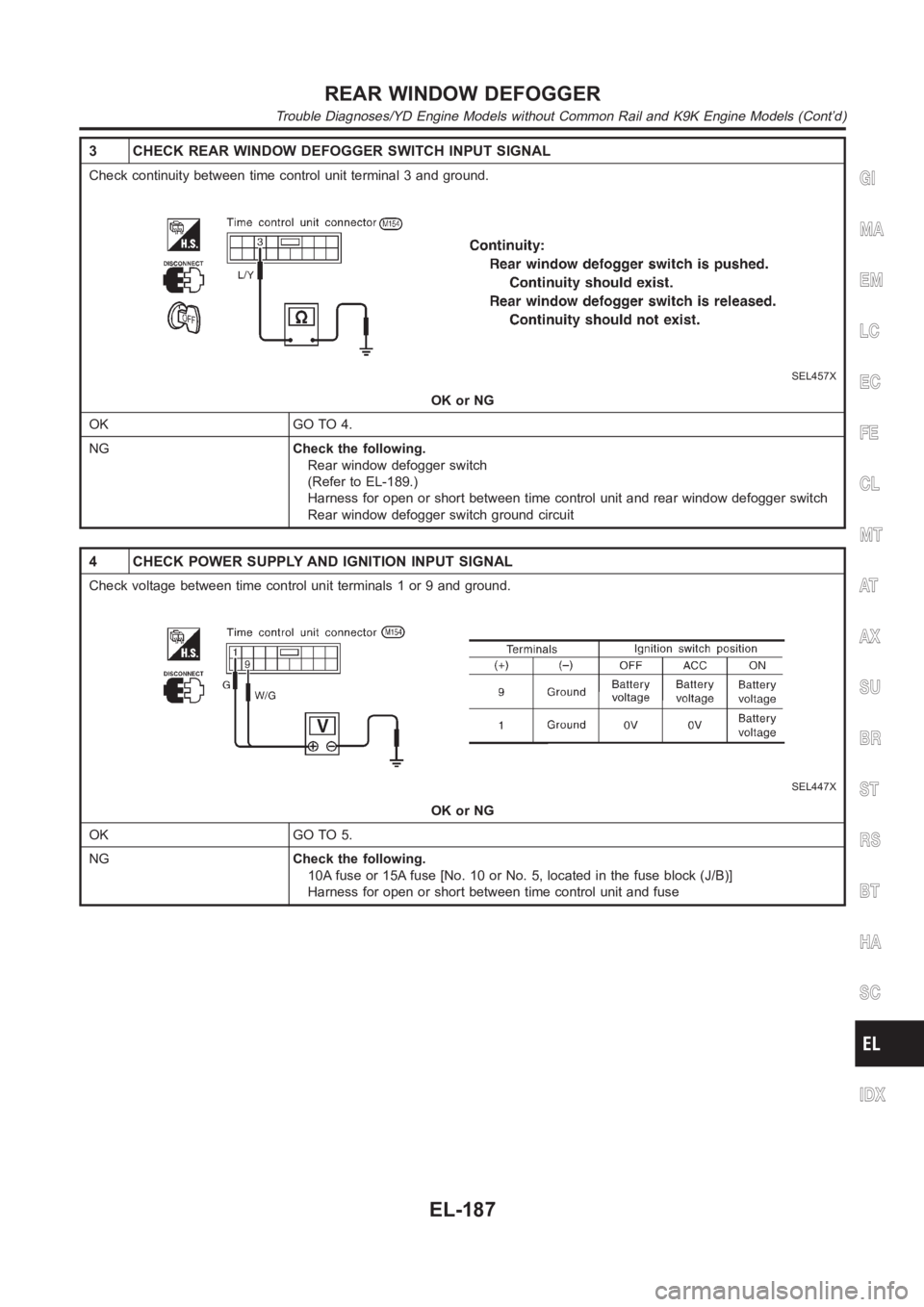
3 CHECK REAR WINDOW DEFOGGER SWITCH INPUT SIGNAL
Check continuity between time control unit terminal 3 and ground.
SEL457X
OK or NG
OK GO TO 4.
NGCheck the following.
Rear window defogger switch
(Refer to EL-189.)
Harness for open or short between time control unit and rear window defogger switch
Rear window defogger switch ground circuit
4 CHECK POWER SUPPLY AND IGNITION INPUT SIGNAL
Check voltage between time control unit terminals 1 or 9 and ground.
SEL447X
OK or NG
OK GO TO 5.
NGCheck the following.
10A fuse or 15A fuse [No. 10 or No. 5, located in the fuse block (J/B)]
Harness for open or short between time control unit and fuse
GI
MA
EM
LC
EC
FE
CL
MT
AT
AX
SU
BR
ST
RS
BT
HA
SC
IDX
REAR WINDOW DEFOGGER
Trouble Diagnoses/YD Engine Models without Common Rail and K9K Engine Models (Cont’d)
EL-187
Page 2524 of 3189
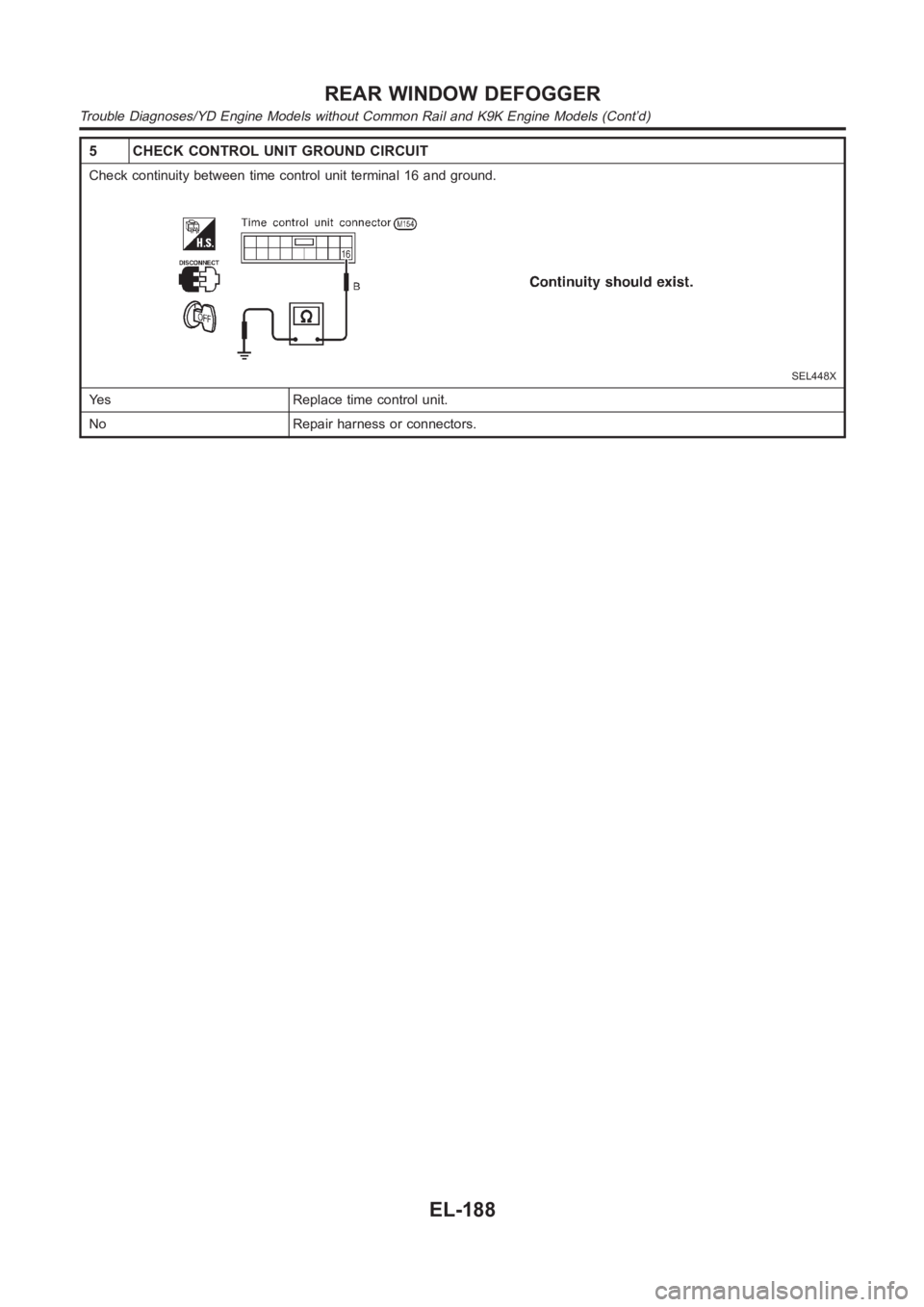
5 CHECK CONTROL UNIT GROUND CIRCUIT
Check continuity between time control unit terminal 16 and ground.
SEL448X
Yes Replace time control unit.
No Repair harness or connectors.
REAR WINDOW DEFOGGER
Trouble Diagnoses/YD Engine Models without Common Rail and K9K Engine Models (Cont’d)
EL-188
Page 2628 of 3189
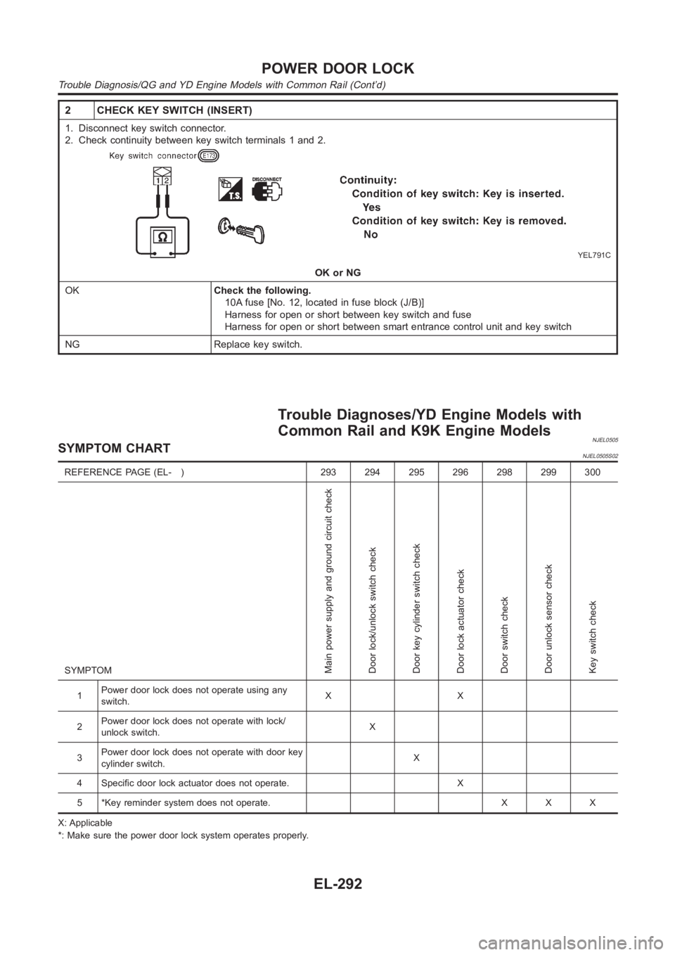
2 CHECK KEY SWITCH (INSERT)
1. Disconnect key switch connector.
2. Check continuity between key switch terminals 1 and 2.
YEL791C
OK or NG
OKCheck the following.
10A fuse [No. 12, located in fuse block (J/B)]
Harness for open or short between key switch and fuse
Harness for open or short between smart entrance control unit and key switch
NG Replace key switch.
Trouble Diagnoses/YD Engine Models with
Common Rail and K9K Engine Models
NJEL0505SYMPTOM CHARTNJEL0505S02
REFERENCE PAGE (EL- ) 293 294 295 296 298 299 300
SYMPTOM
Main power supply and ground circuit check
Door lock/unlock switch check
Door key cylinder switch check
Door lock actuator check
Door switch check
Door unlock sensor check
Key switch check
1Power door lock does not operate using any
switch.XX
2Power door lock does not operate with lock/
unlock switch.X
3Power door lock does not operate with door key
cylinder switch.X
4 Specific door lock actuator does not operate. X
5 *Key reminder system does not operate. X X X
X: Applicable
*: Make sure the power door lock system operates properly.
POWER DOOR LOCK
Trouble Diagnosis/QG and YD Engine Models with Common Rail (Cont’d)
EL-292
Page 2629 of 3189
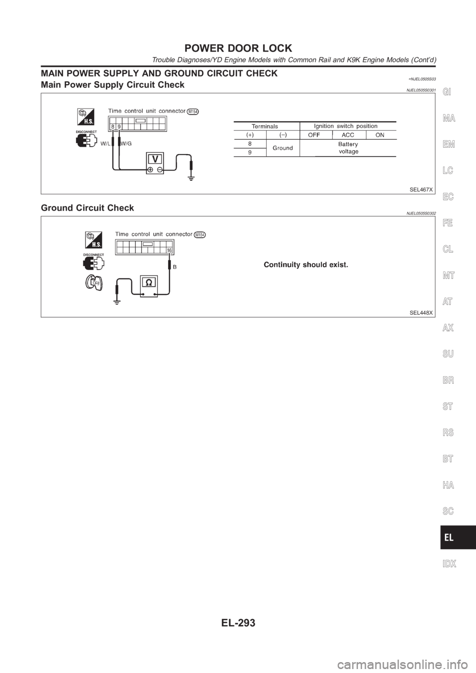
MAIN POWER SUPPLY AND GROUND CIRCUIT CHECK=NJEL0505S03Main Power Supply Circuit CheckNJEL0505S0301
SEL467X
Ground Circuit CheckNJEL0505S0302
SEL448X
GI
MA
EM
LC
EC
FE
CL
MT
AT
AX
SU
BR
ST
RS
BT
HA
SC
IDX
POWER DOOR LOCK
Trouble Diagnoses/YD Engine Models with Common Rail and K9K Engine Models(Cont’d)
EL-293
Page 2630 of 3189
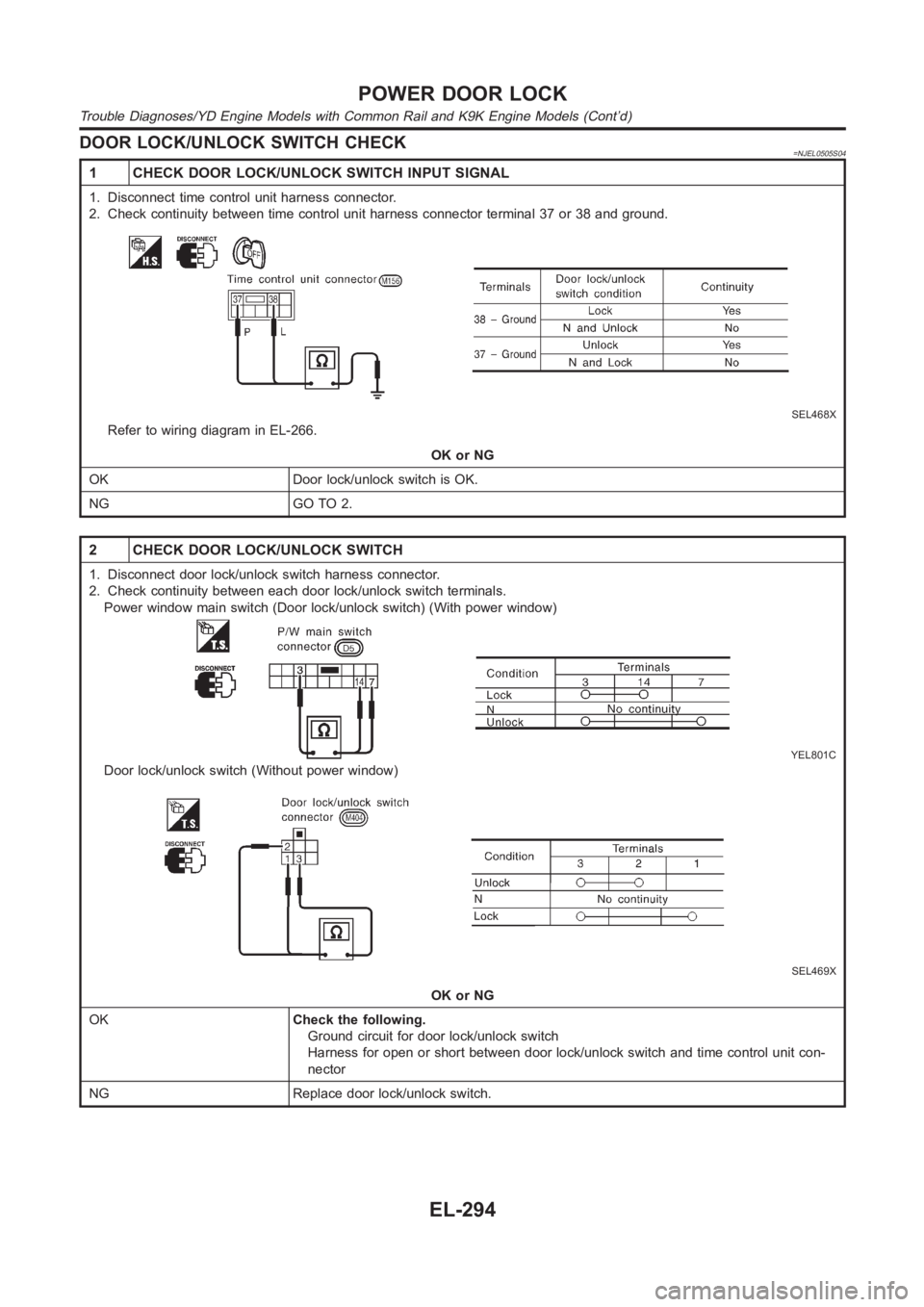
DOOR LOCK/UNLOCK SWITCH CHECK=NJEL0505S04
1 CHECK DOOR LOCK/UNLOCK SWITCH INPUT SIGNAL
1. Disconnect time control unit harness connector.
2. Check continuity between time control unit harness connector terminal37 or 38 and ground.
SEL468X
Refer to wiring diagram in EL-266.
OK or NG
OK Door lock/unlock switch is OK.
NG GO TO 2.
2 CHECK DOOR LOCK/UNLOCK SWITCH
1. Disconnect door lock/unlock switch harness connector.
2. Check continuity between each door lock/unlock switch terminals.
Power window main switch (Door lock/unlock switch) (With power window)
YEL801C
Door lock/unlock switch (Without power window)
SEL469X
OK or NG
OKCheck the following.
Ground circuit for door lock/unlock switch
Harness for open or short between door lock/unlock switch and time controlunit con-
nector
NG Replace door lock/unlock switch.
POWER DOOR LOCK
Trouble Diagnoses/YD Engine Models with Common Rail and K9K Engine Models(Cont’d)
EL-294
Page 2631 of 3189
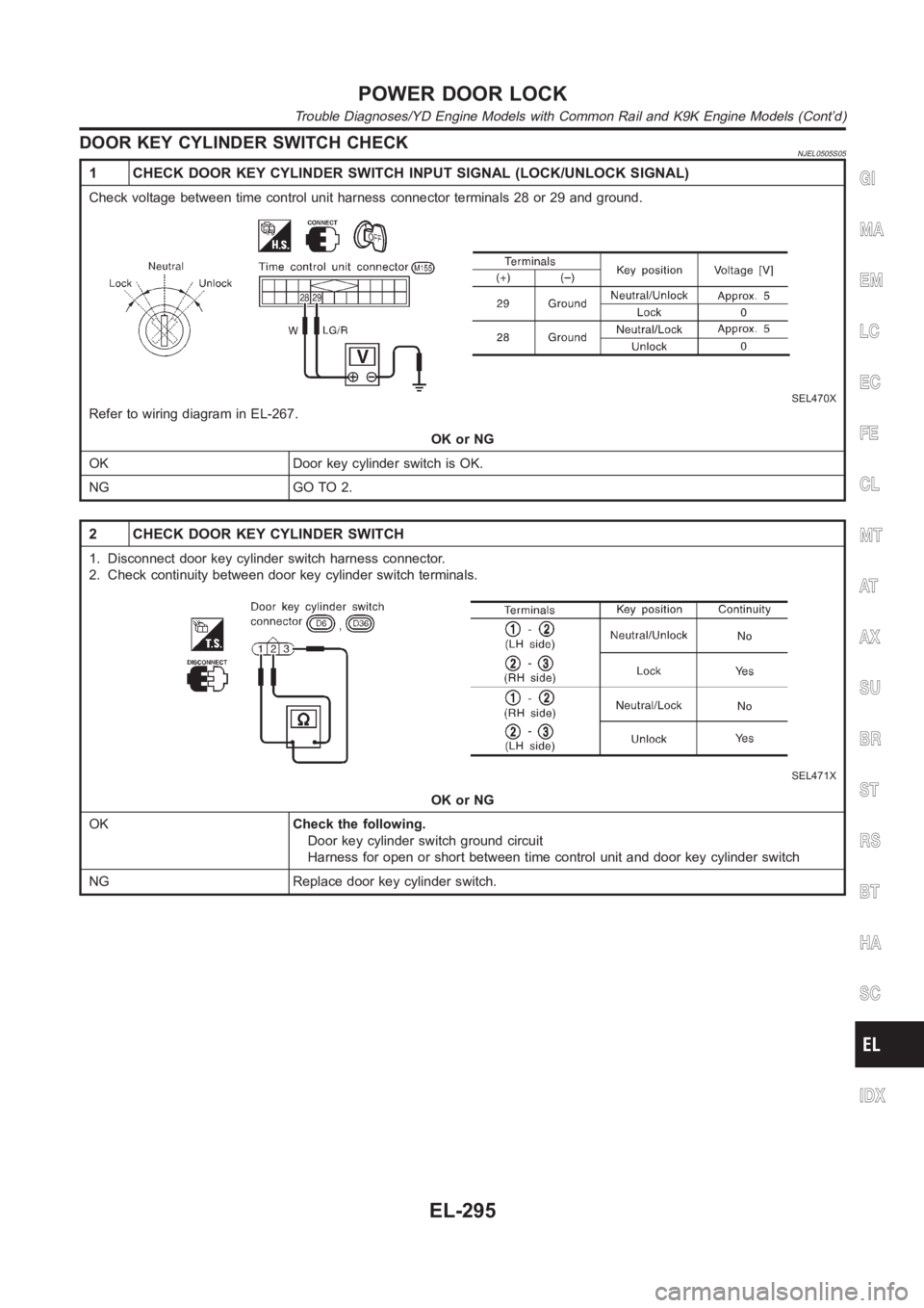
DOOR KEY CYLINDER SWITCH CHECKNJEL0505S05
1 CHECK DOOR KEY CYLINDER SWITCH INPUT SIGNAL (LOCK/UNLOCK SIGNAL)
Check voltage between time control unit harness connector terminals 28 or29 and ground.
SEL470X
Refer to wiring diagram in EL-267.
OK or NG
OK Door key cylinder switch is OK.
NG GO TO 2.
2 CHECK DOOR KEY CYLINDER SWITCH
1. Disconnect door key cylinder switch harness connector.
2. Check continuity between door key cylinder switch terminals.
SEL471X
OK or NG
OKCheck the following.
Door key cylinder switch ground circuit
Harness for open or short between time control unit and door key cylinder switch
NG Replace door key cylinder switch.
GI
MA
EM
LC
EC
FE
CL
MT
AT
AX
SU
BR
ST
RS
BT
HA
SC
IDX
POWER DOOR LOCK
Trouble Diagnoses/YD Engine Models with Common Rail and K9K Engine Models(Cont’d)
EL-295
Page 2632 of 3189
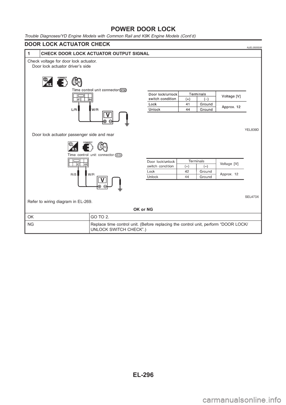
DOOR LOCK ACTUATOR CHECKNJEL0505S06
1 CHECK DOOR LOCK ACTUATOR OUTPUT SIGNAL
Check voltage for door lock actuator.
Door lock actuator driver’s side
YEL839D
Door lock actuator passenger side and rear
SEL473X
Refer to wiring diagram in EL-269.
OK or NG
OK GO TO 2.
NG Replace time control unit. (Before replacing the control unit, perform“DOOR LOCK/
UNLOCK SWITCH CHECK”.)
POWER DOOR LOCK
Trouble Diagnoses/YD Engine Models with Common Rail and K9K Engine Models(Cont’d)
EL-296