k9k NISSAN ALMERA N16 2003 Electronic Service Manual
[x] Cancel search | Manufacturer: NISSAN, Model Year: 2003, Model line: ALMERA N16, Model: NISSAN ALMERA N16 2003Pages: 3189, PDF Size: 54.76 MB
Page 2681 of 3189
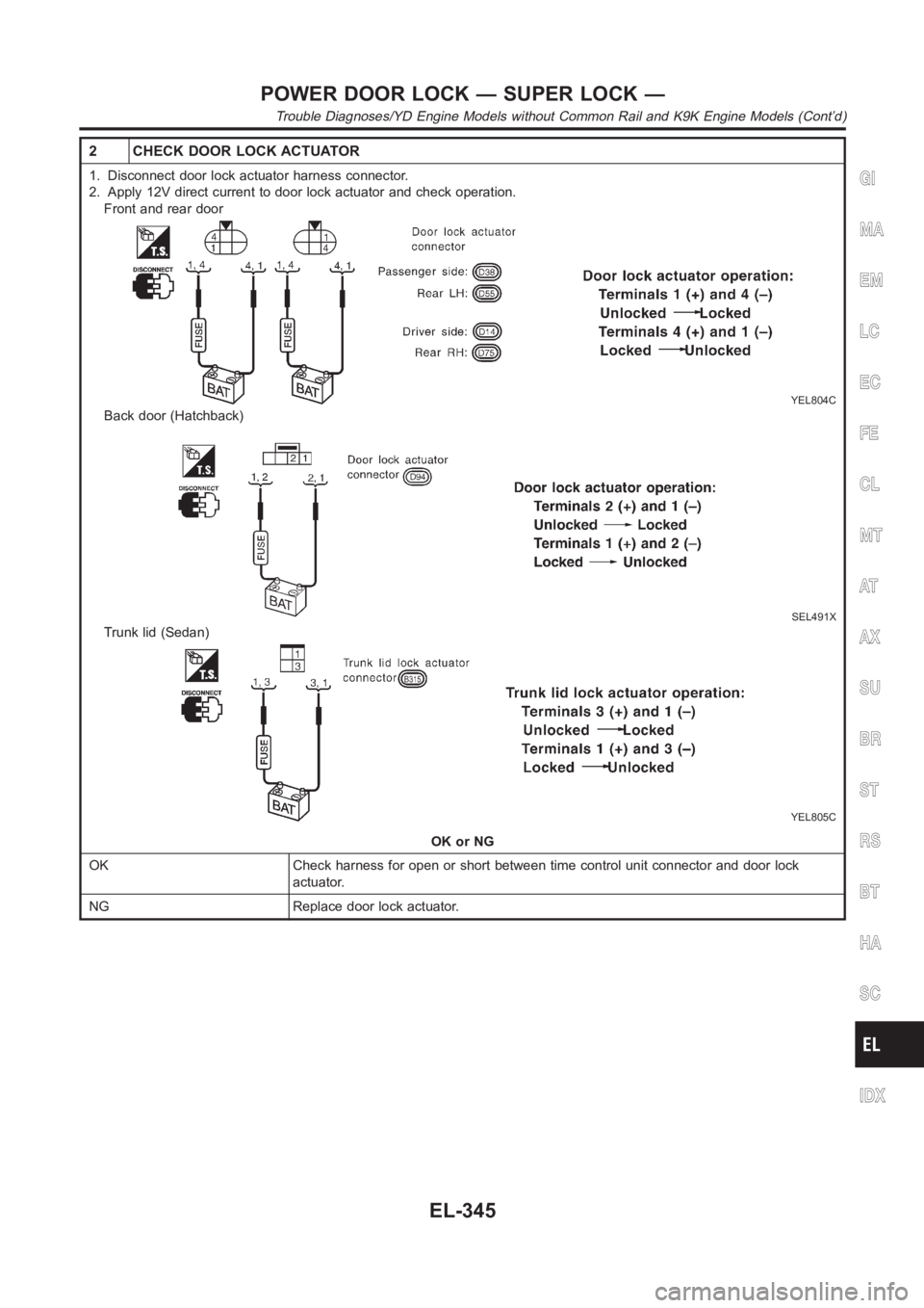
2 CHECK DOOR LOCK ACTUATOR
1. Disconnect door lock actuator harness connector.
2. Apply 12V direct current to door lock actuator and check operation.
Front and rear door
YEL804C
Back door (Hatchback)
SEL491X
Trunk lid (Sedan)
YEL805C
OK or NG
OK Check harness for open or short between time control unit connector and door lock
actuator.
NG Replace door lock actuator.
GI
MA
EM
LC
EC
FE
CL
MT
AT
AX
SU
BR
ST
RS
BT
HA
SC
IDX
POWER DOOR LOCK — SUPER LOCK —
Trouble Diagnoses/YD Engine Models without Common Rail and K9K Engine Models (Cont’d)
EL-345
Page 2682 of 3189
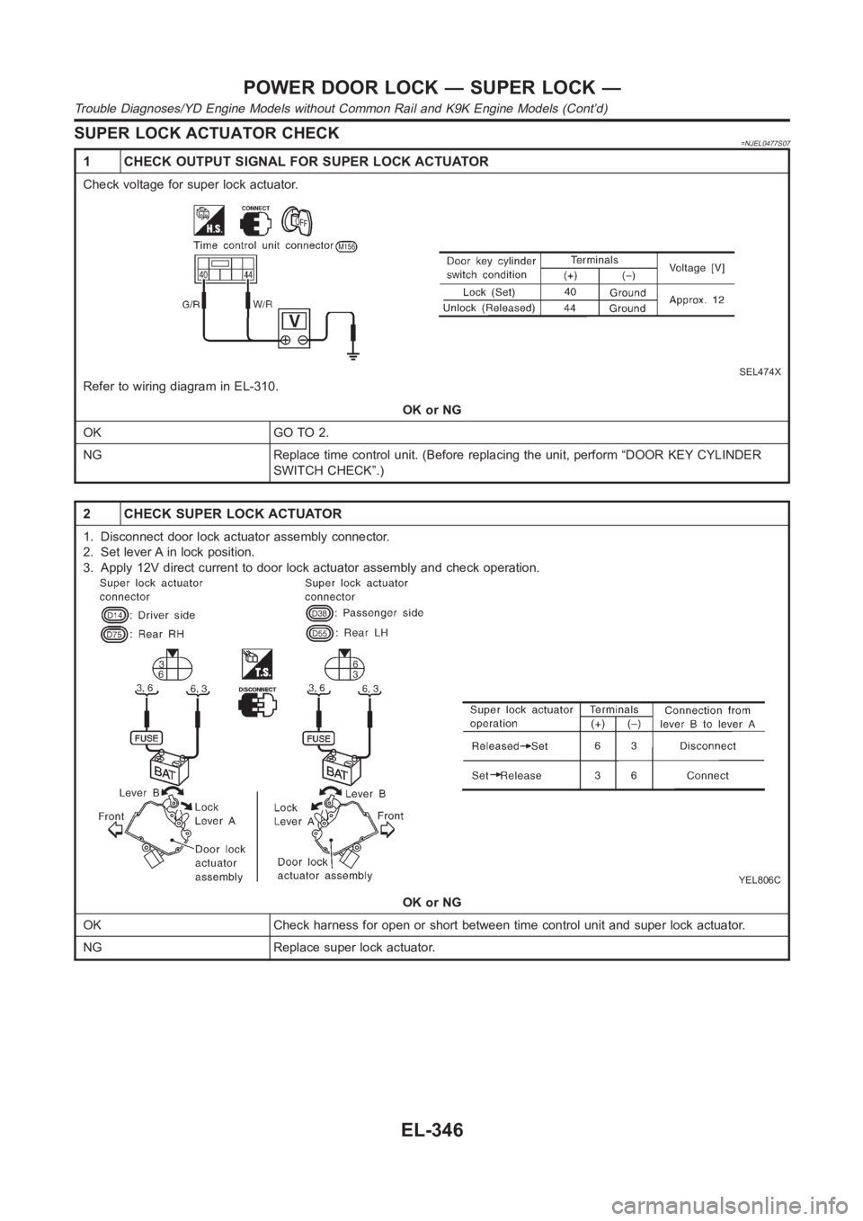
SUPER LOCK ACTUATOR CHECK=NJEL0477S07
1 CHECK OUTPUT SIGNAL FOR SUPER LOCK ACTUATOR
Check voltage for super lock actuator.
SEL474X
Refer to wiring diagram in EL-310.
OK or NG
OK GO TO 2.
NG Replace time control unit. (Before replacing the unit, perform “DOOR KEY CYLINDER
SWITCH CHECK”.)
2 CHECK SUPER LOCK ACTUATOR
1. Disconnect door lock actuator assembly connector.
2. Set lever A in lock position.
3. Apply 12V direct current to door lock actuator assembly and check operation.
YEL806C
OK or NG
OK Check harness for open or short between time control unit and super lock actuator.
NG Replace super lock actuator.
POWER DOOR LOCK — SUPER LOCK —
Trouble Diagnoses/YD Engine Models without Common Rail and K9K Engine Models (Cont’d)
EL-346
Page 2683 of 3189
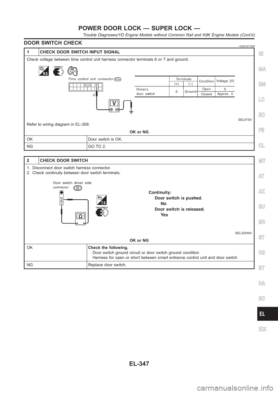
DOOR SWITCH CHECK=NJEL0477S08
1 CHECK DOOR SWITCH INPUT SIGNAL
Check voltage between time control unit harness connector terminals 6 or 7and ground.
SEL475X
Refer to wiring diagram in EL-309.
OK or NG
OK Door switch is OK.
NG GO TO 2.
2 CHECK DOOR SWITCH
1. Disconnect door switch harness connector.
2. Check continuity between door switch terminals.
SEL325WA
OK or NG
OKCheck the following.
Door switch ground circuit or door switch ground condition
Harness for open or short between smart entrance control unit and door switch
NG Replace door switch.
GI
MA
EM
LC
EC
FE
CL
MT
AT
AX
SU
BR
ST
RS
BT
HA
SC
IDX
POWER DOOR LOCK — SUPER LOCK —
Trouble Diagnoses/YD Engine Models without Common Rail and K9K Engine Models (Cont’d)
EL-347
Page 2684 of 3189
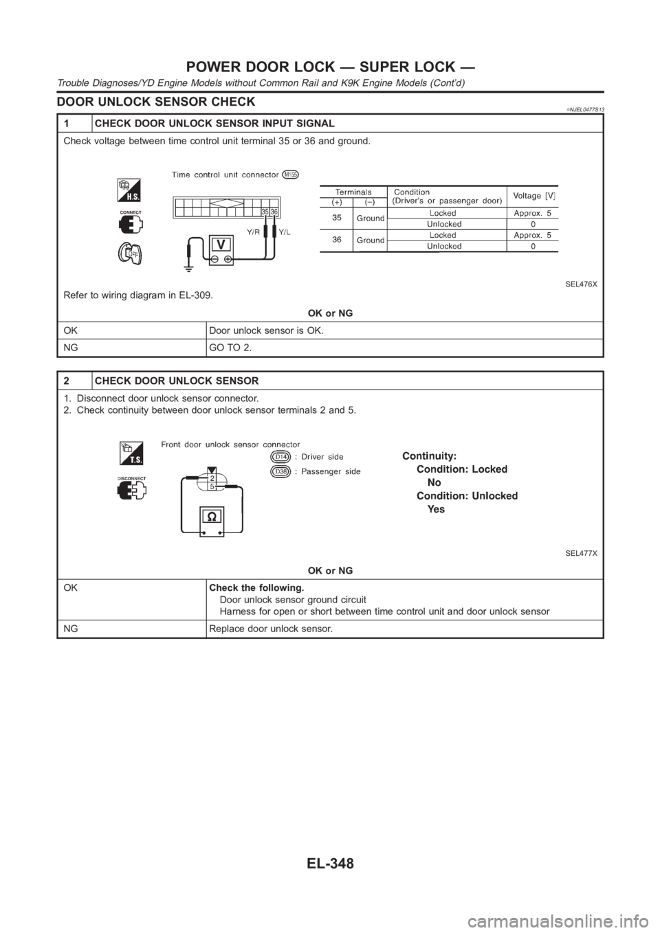
DOOR UNLOCK SENSOR CHECK=NJEL0477S13
1 CHECK DOOR UNLOCK SENSOR INPUT SIGNAL
Check voltage between time control unit terminal 35 or 36 and ground.
SEL476X
Refer to wiring diagram in EL-309.
OK or NG
OK Door unlock sensor is OK.
NG GO TO 2.
2 CHECK DOOR UNLOCK SENSOR
1. Disconnect door unlock sensor connector.
2. Check continuity between door unlock sensor terminals 2 and 5.
SEL477X
OK or NG
OKCheck the following.
Door unlock sensor ground circuit
Harness for open or short between time control unit and door unlock sensor
NG Replace door unlock sensor.
POWER DOOR LOCK — SUPER LOCK —
Trouble Diagnoses/YD Engine Models without Common Rail and K9K Engine Models (Cont’d)
EL-348
Page 2685 of 3189
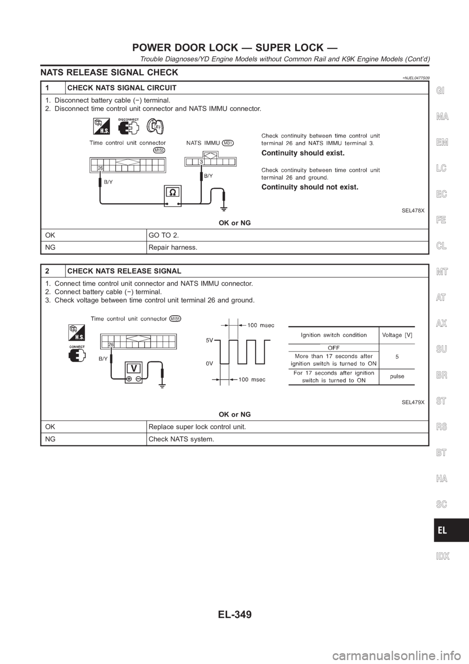
NATS RELEASE SIGNAL CHECK=NJEL0477S09
1 CHECK NATS SIGNAL CIRCUIT
1. Disconnect battery cable (−) terminal.
2. Disconnect time control unit connector and NATS IMMU connector.
SEL478X
OK or NG
OK GO TO 2.
NG Repair harness.
2 CHECK NATS RELEASE SIGNAL
1. Connect time control unit connector and NATS IMMU connector.
2. Connect battery cable (−) terminal.
3. Check voltage between time control unit terminal 26 and ground.
SEL479X
OK or NG
OK Replace super lock control unit.
NG Check NATS system.
GI
MA
EM
LC
EC
FE
CL
MT
AT
AX
SU
BR
ST
RS
BT
HA
SC
IDX
POWER DOOR LOCK — SUPER LOCK —
Trouble Diagnoses/YD Engine Models without Common Rail and K9K Engine Models (Cont’d)
EL-349
Page 2686 of 3189
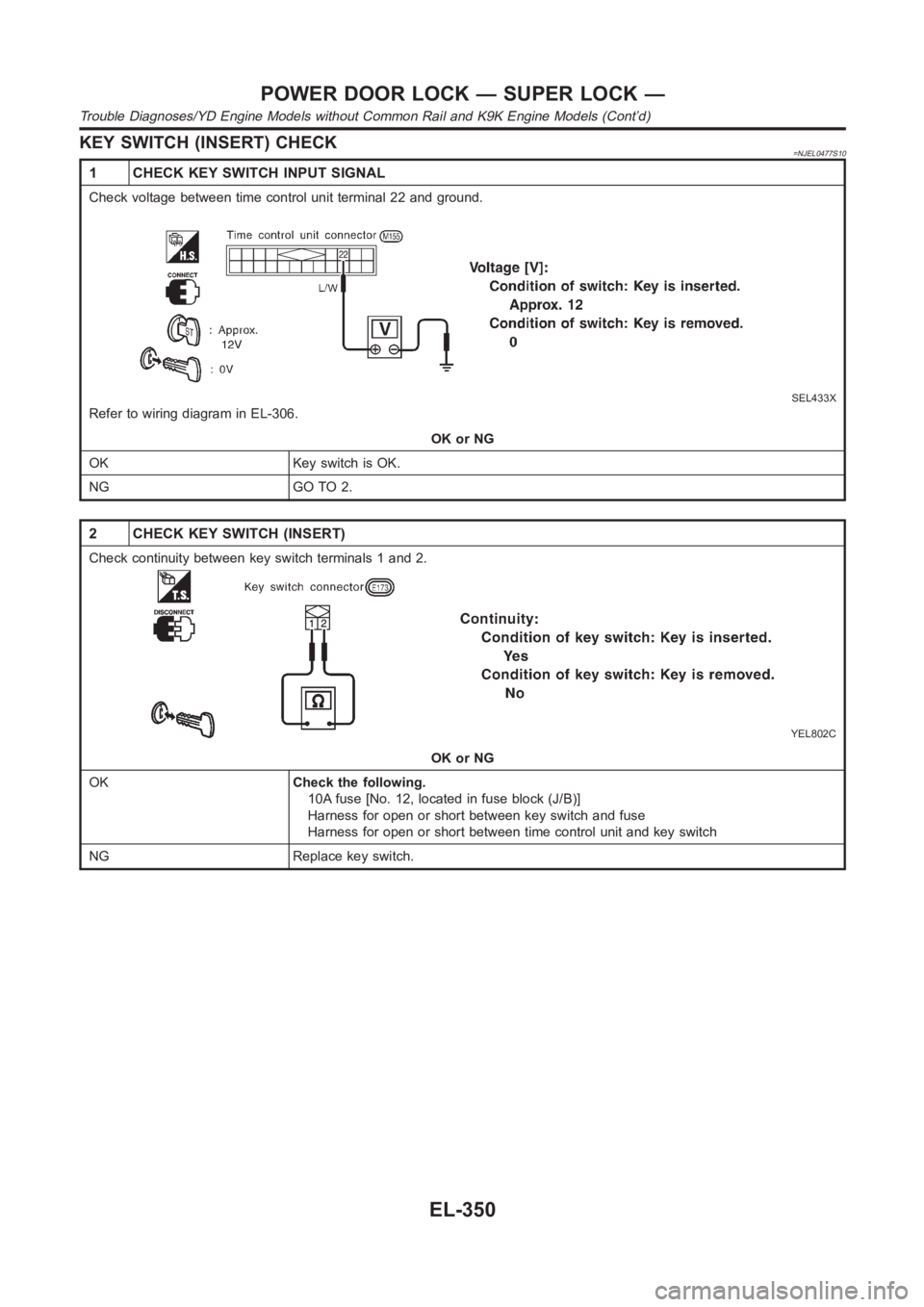
KEY SWITCH (INSERT) CHECK=NJEL0477S10
1 CHECK KEY SWITCH INPUT SIGNAL
Check voltage between time control unit terminal 22 and ground.
SEL433X
Refer to wiring diagram in EL-306.
OK or NG
OK Key switch is OK.
NG GO TO 2.
2 CHECK KEY SWITCH (INSERT)
Check continuity between key switch terminals 1 and 2.
YEL802C
OK or NG
OKCheck the following.
10A fuse [No. 12, located in fuse block (J/B)]
Harness for open or short between key switch and fuse
Harness for open or short between time control unit and key switch
NG Replace key switch.
POWER DOOR LOCK — SUPER LOCK —
Trouble Diagnoses/YD Engine Models without Common Rail and K9K Engine Models (Cont’d)
EL-350
Page 2687 of 3189
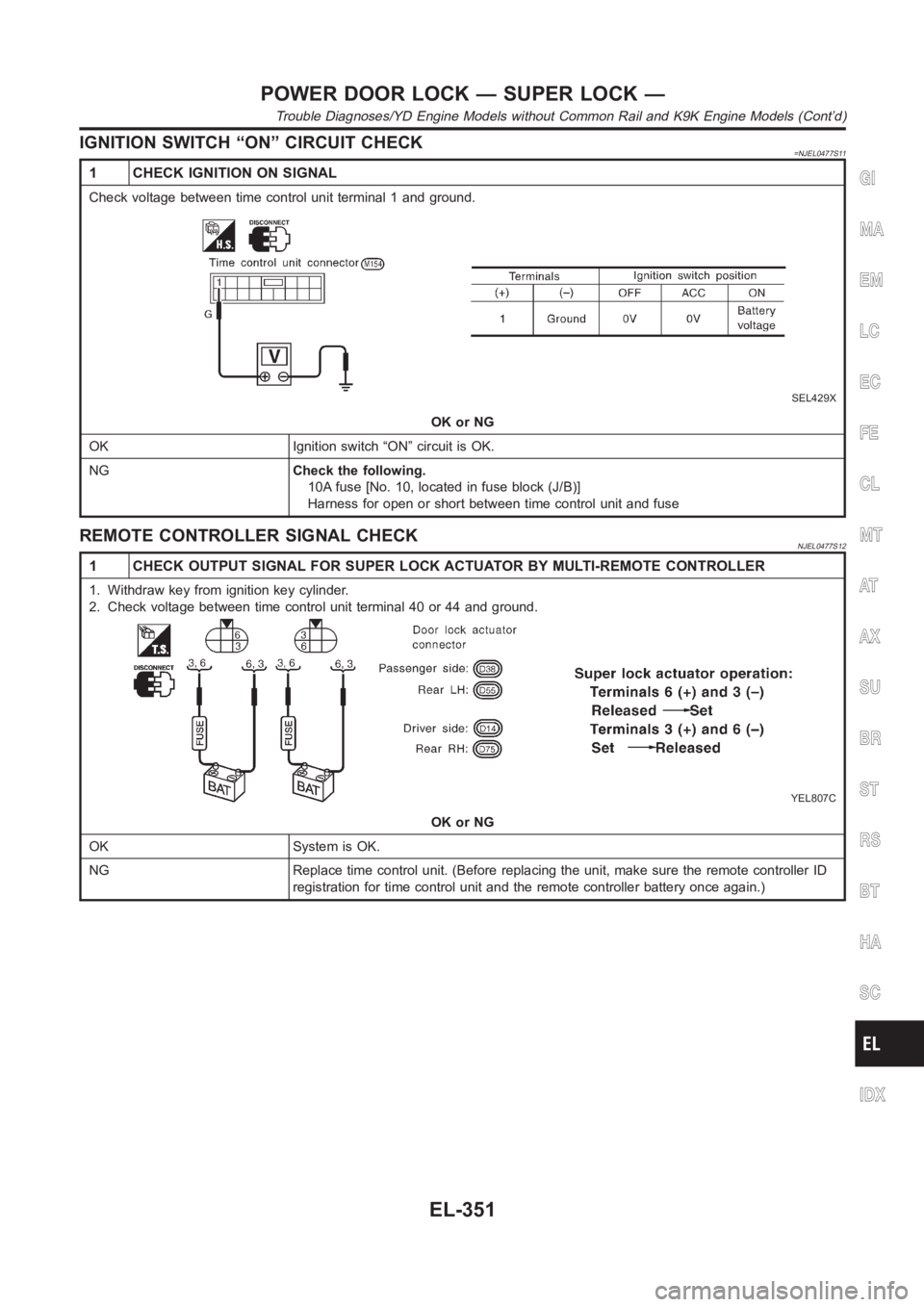
IGNITION SWITCH “ON” CIRCUIT CHECK=NJEL0477S11
1 CHECK IGNITION ON SIGNAL
Check voltage between time control unit terminal 1 and ground.
SEL429X
OK or NG
OK Ignition switch “ON” circuit is OK.
NGCheck the following.
10A fuse [No. 10, located in fuse block (J/B)]
Harness for open or short between time control unit and fuse
REMOTE CONTROLLER SIGNAL CHECKNJEL0477S12
1 CHECK OUTPUT SIGNAL FOR SUPER LOCK ACTUATOR BY MULTI-REMOTE CONTROLLER
1. Withdraw key from ignition key cylinder.
2. Check voltage between time control unit terminal 40 or 44 and ground.
YEL807C
OK or NG
OK System is OK.
NG Replace time control unit. (Before replacing the unit, make sure the remote controller ID
registration for time control unit and the remote controller battery onceagain.)
GI
MA
EM
LC
EC
FE
CL
MT
AT
AX
SU
BR
ST
RS
BT
HA
SC
IDX
POWER DOOR LOCK — SUPER LOCK —
Trouble Diagnoses/YD Engine Models without Common Rail and K9K Engine Models (Cont’d)
EL-351
Page 2696 of 3189
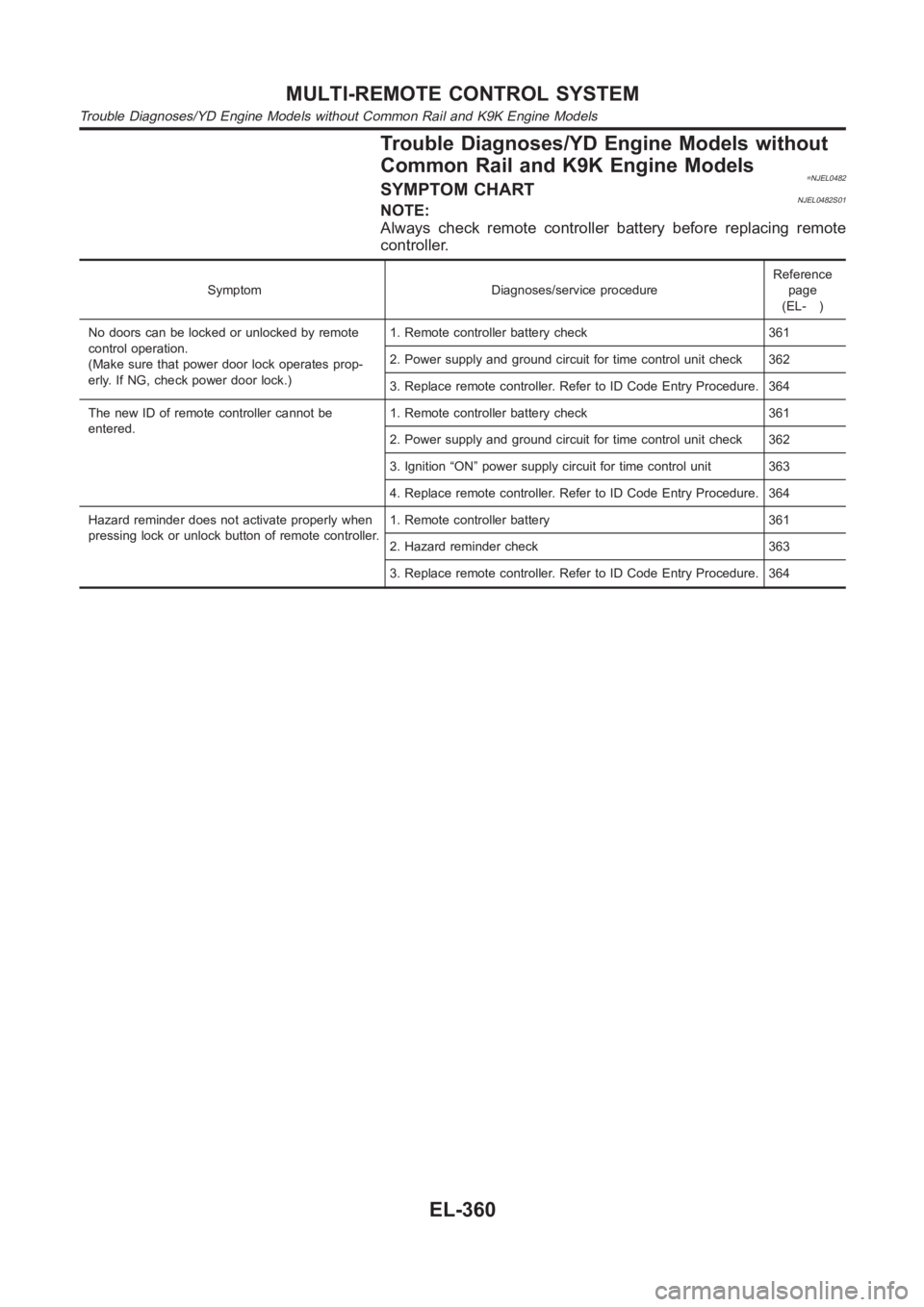
Trouble Diagnoses/YD Engine Models without
Common Rail and K9K Engine Models
=NJEL0482SYMPTOM CHARTNJEL0482S01NOTE:
Always check remote controller battery before replacing remote
controller.
Symptom Diagnoses/service procedureReference
page
(EL- )
No doors can be locked or unlocked by remote
control operation.
(Make sure that power door lock operates prop-
erly. If NG, check power door lock.)1. Remote controller battery check 361
2. Power supply and ground circuit for time control unit check 362
3. Replace remote controller. Refer to ID Code Entry Procedure. 364
The new ID of remote controller cannot be
entered.1. Remote controller battery check 361
2. Power supply and ground circuit for time control unit check 362
3. Ignition “ON” power supply circuit for time control unit 363
4. Replace remote controller. Refer to ID Code Entry Procedure. 364
Hazard reminder does not activate properly when
pressing lock or unlock button of remote controller.1. Remote controller battery 361
2. Hazard reminder check 363
3. Replace remote controller. Refer to ID Code Entry Procedure. 364
MULTI-REMOTE CONTROL SYSTEM
Trouble Diagnoses/YD Engine Models without Common Rail and K9K Engine Models
EL-360
Page 2697 of 3189
REMOTE CONTROLLER BATTERY AND FUNCTION
CHECK
=NJEL0482S02
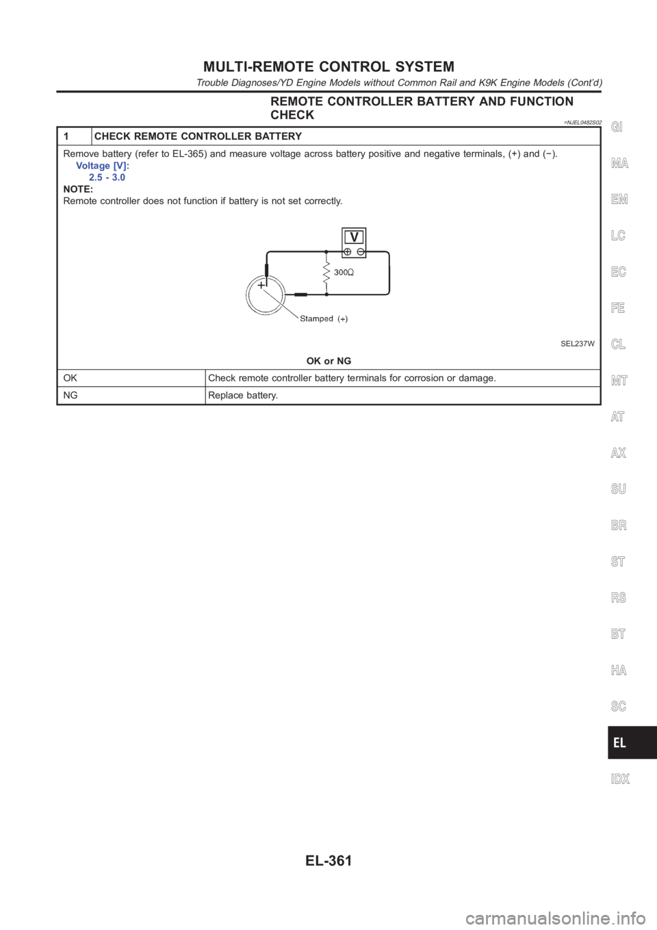
1 CHECK REMOTE CONTROLLER BATTERY
Remove battery (refer to EL-365) and measure voltage across battery positive and negative terminals, (+) and (−).
Voltage [V]:
2.5 - 3.0
NOTE:
Remote controller does not function if battery is not set correctly.
SEL237W
OK or NG
OK Check remote controller battery terminals for corrosion or damage.
NG Replace battery.
GI
MA
EM
LC
EC
FE
CL
MT
AT
AX
SU
BR
ST
RS
BT
HA
SC
IDX
MULTI-REMOTE CONTROL SYSTEM
Trouble Diagnoses/YD Engine Models without Common Rail and K9K Engine Models (Cont’d)
EL-361
Page 2698 of 3189
POWER SUPPLY AND GROUND CIRCUIT CHECK=NJEL0482S03
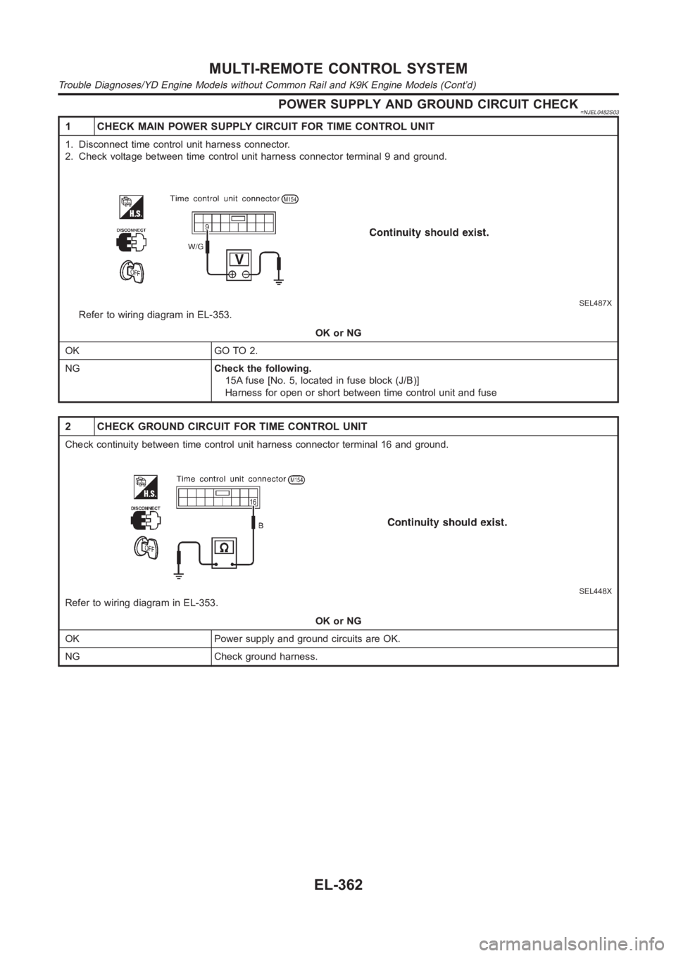
1 CHECK MAIN POWER SUPPLY CIRCUIT FOR TIME CONTROL UNIT
1. Disconnect time control unit harness connector.
2. Check voltage between time control unit harness connector terminal 9 and ground.
SEL487X
Refer to wiring diagram in EL-353.
OK or NG
OK GO TO 2.
NGCheck the following.
15A fuse [No. 5, located in fuse block (J/B)]
Harness for open or short between time control unit and fuse
2 CHECK GROUND CIRCUIT FOR TIME CONTROL UNIT
Check continuity between time control unit harness connector terminal 16and ground.
SEL448X
Refer to wiring diagram in EL-353.
OK or NG
OK Power supply and ground circuits are OK.
NG Check ground harness.
MULTI-REMOTE CONTROL SYSTEM
Trouble Diagnoses/YD Engine Models without Common Rail and K9K Engine Models (Cont’d)
EL-362