Time NISSAN ALMERA N16 2003 Electronic Repair Manual
[x] Cancel search | Manufacturer: NISSAN, Model Year: 2003, Model line: ALMERA N16, Model: NISSAN ALMERA N16 2003Pages: 3189, PDF Size: 54.76 MB
Page 3098 of 3189
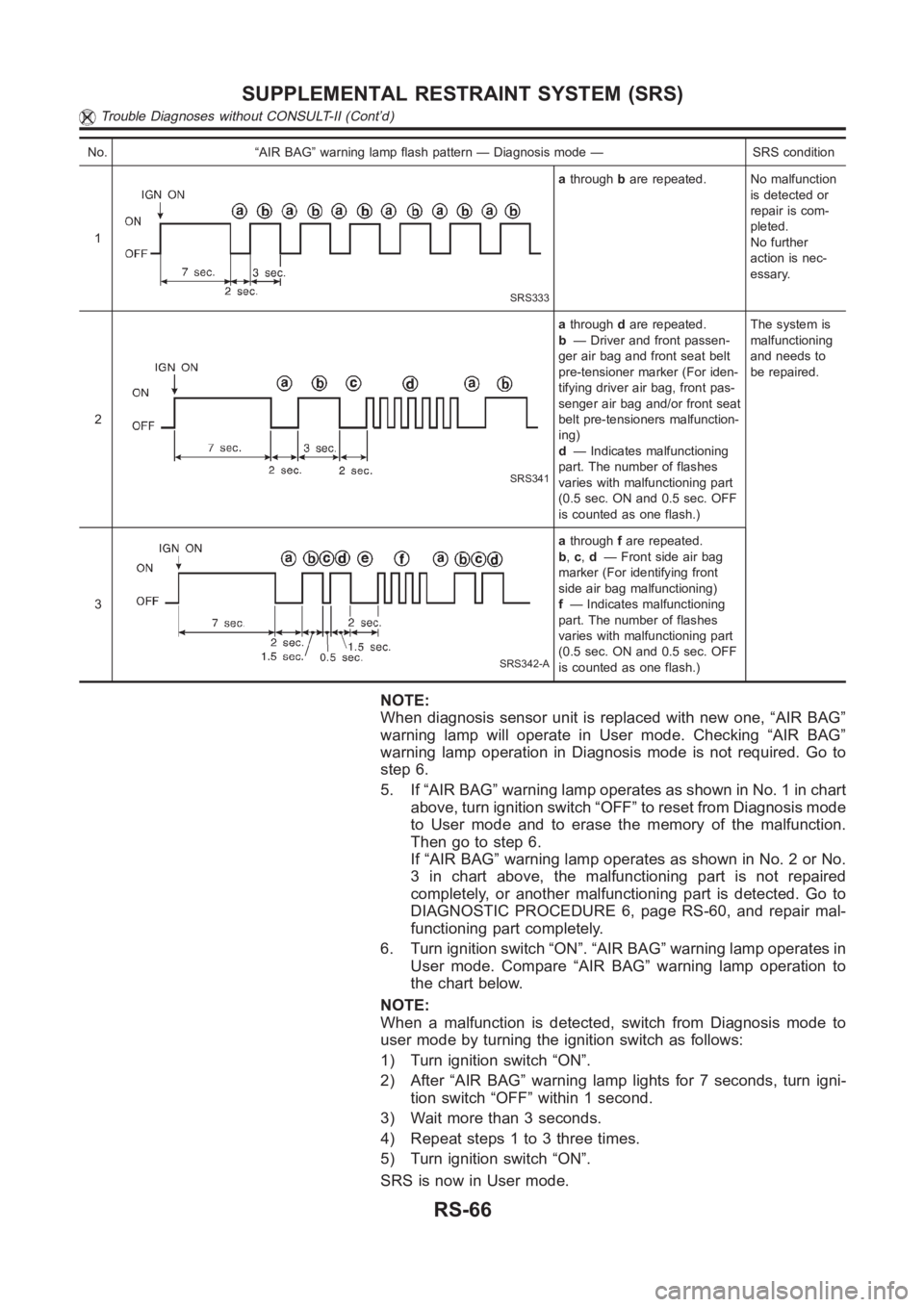
No. “AIR BAG” warning lamp flash pattern — Diagnosis mode — SRS condition
1
SRS333
athroughbare repeated. No malfunction
is detected or
repair is com-
pleted.
No further
action is nec-
essary.
2
SRS341
athroughdare repeated.
b— Driver and front passen-
ger air bag and front seat belt
pre-tensioner marker (For iden-
tifying driver air bag, front pas-
senger air bag and/or front seat
belt pre-tensioners malfunction-
ing)
d— Indicates malfunctioning
part. The number of flashes
varies with malfunctioning part
(0.5 sec. ON and 0.5 sec. OFF
is counted as one flash.)The system is
malfunctioning
and needs to
be repaired.
3
SRS342-A
athroughfare repeated.
b,c,d— Front side air bag
marker (For identifying front
side air bag malfunctioning)
f— Indicates malfunctioning
part. The number of flashes
varies with malfunctioning part
(0.5 sec. ON and 0.5 sec. OFF
is counted as one flash.)
NOTE:
When diagnosis sensor unit is replaced with new one, “AIR BAG”
warning lamp will operate in User mode. Checking “AIR BAG”
warning lamp operation in Diagnosis mode is not required. Go to
step 6.
5. If “AIR BAG” warning lamp operates as shown in No. 1 in chart
above, turn ignition switch “OFF” to reset from Diagnosis mode
to User mode and to erase the memory of the malfunction.
Then go to step 6.
If “AIR BAG” warning lamp operates as shown in No. 2 or No.
3 in chart above, the malfunctioning part is not repaired
completely, or another malfunctioning part is detected. Go to
DIAGNOSTIC PROCEDURE 6, page RS-60, and repair mal-
functioning part completely.
6. Turn ignition switch “ON”. “AIR BAG” warning lamp operates in
User mode. Compare “AIR BAG” warning lamp operation to
the chart below.
NOTE:
When a malfunction is detected, switch from Diagnosis mode to
user mode by turning the ignition switch as follows:
1) Turn ignition switch “ON”.
2) After “AIR BAG” warning lamp lights for 7 seconds, turn igni-
tion switch “OFF” within 1 second.
3) Wait more than 3 seconds.
4) Repeat steps 1 to 3 three times.
5) Turn ignition switch “ON”.
SRS is now in User mode.
SUPPLEMENTAL RESTRAINT SYSTEM (SRS)
Trouble Diagnoses without CONSULT-II (Cont’d)
RS-66
Page 3099 of 3189
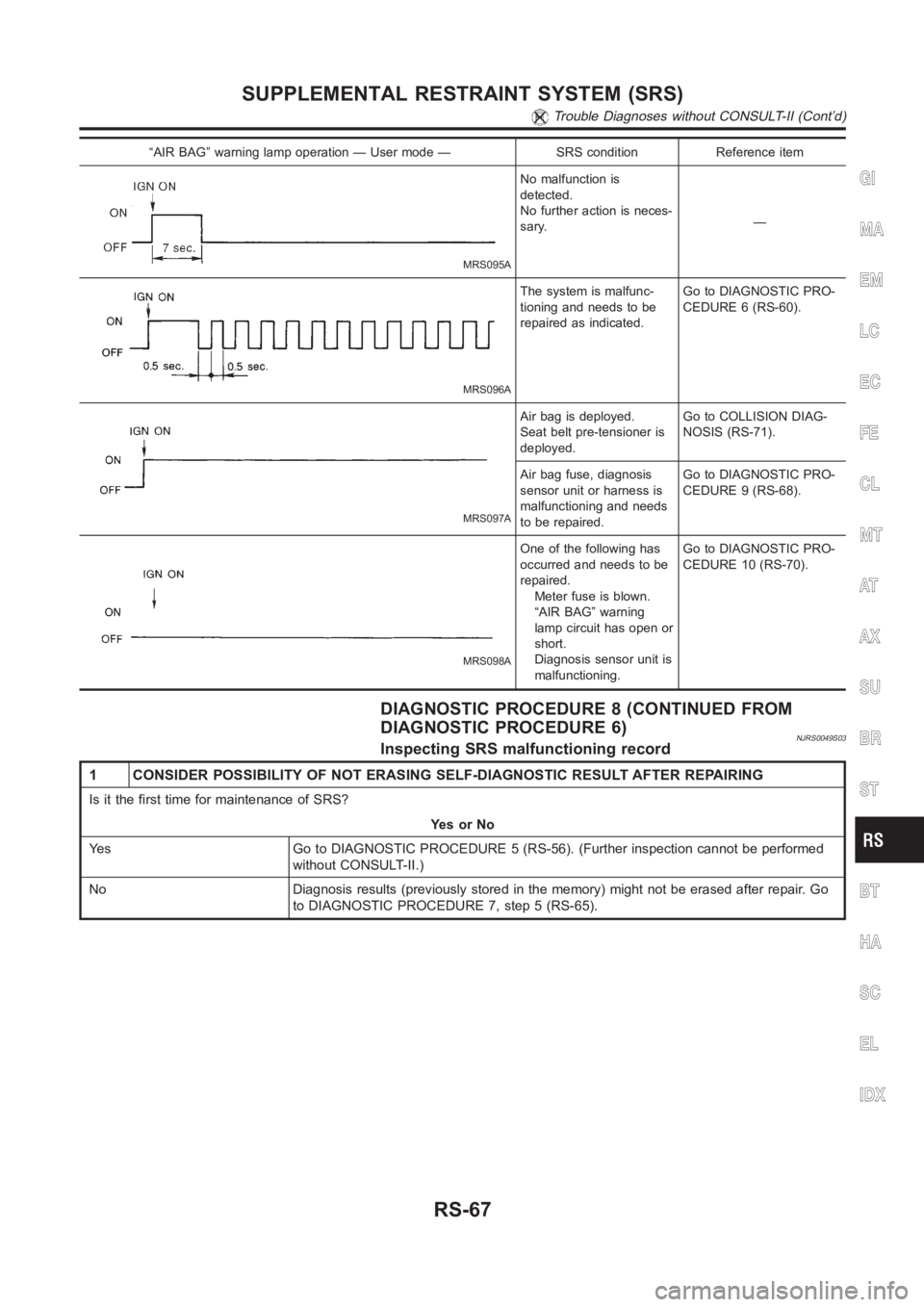
“AIR BAG” warning lamp operation — User mode — SRS condition Reference item
MRS095A
No malfunction is
detected.
No further action is neces-
sary.—
MRS096A
The system is malfunc-
tioning and needs to be
repaired as indicated.Go to DIAGNOSTIC PRO-
CEDURE 6 (RS-60).
MRS097A
Air bag is deployed.
Seat belt pre-tensioner is
deployed.Go to COLLISION DIAG-
NOSIS (RS-71).
Air bag fuse, diagnosis
sensor unit or harness is
malfunctioning and needs
to be repaired.Go to DIAGNOSTIC PRO-
CEDURE 9 (RS-68).
MRS098A
One of the following has
occurred and needs to be
repaired.
Meter fuse is blown.
“AIR BAG” warning
lamp circuit has open or
short.
Diagnosis sensor unit is
malfunctioning.Go to DIAGNOSTIC PRO-
CEDURE 10 (RS-70).
DIAGNOSTIC PROCEDURE 8 (CONTINUED FROM
DIAGNOSTIC PROCEDURE 6)
NJRS0049S03Inspecting SRS malfunctioning record
1 CONSIDER POSSIBILITY OF NOT ERASING SELF-DIAGNOSTIC RESULT AFTER REPAIRING
Is it the first time for maintenance of SRS?
YesorNo
Yes Go to DIAGNOSTIC PROCEDURE 5 (RS-56). (Further inspection cannot be performed
without CONSULT-II.)
No Diagnosis results (previously stored in the memory) might not be erasedafter repair. Go
to DIAGNOSTIC PROCEDURE 7, step 5 (RS-65).
GI
MA
EM
LC
EC
FE
CL
MT
AT
AX
SU
BR
ST
BT
HA
SC
EL
IDX
SUPPLEMENTAL RESTRAINT SYSTEM (SRS)
Trouble Diagnoses without CONSULT-II (Cont’d)
RS-67
Page 3109 of 3189
How to Handle BatteryNJSC0003CAUTION:
If it becomes necessary to start the engine with a booster
battery and jumper cables,
1) Use a 12-volt booster battery.
2) After connecting battery cables, ensure that they are
tightly clamped to battery terminals for good contact.
3) Never add distilled water through the hole used to check
specific gravity.
MEL040F
METHODS OF PREVENTING OVER-DISCHARGENJSC0003S01The following precautions must be taken to prevent over-discharg-
ing a battery.
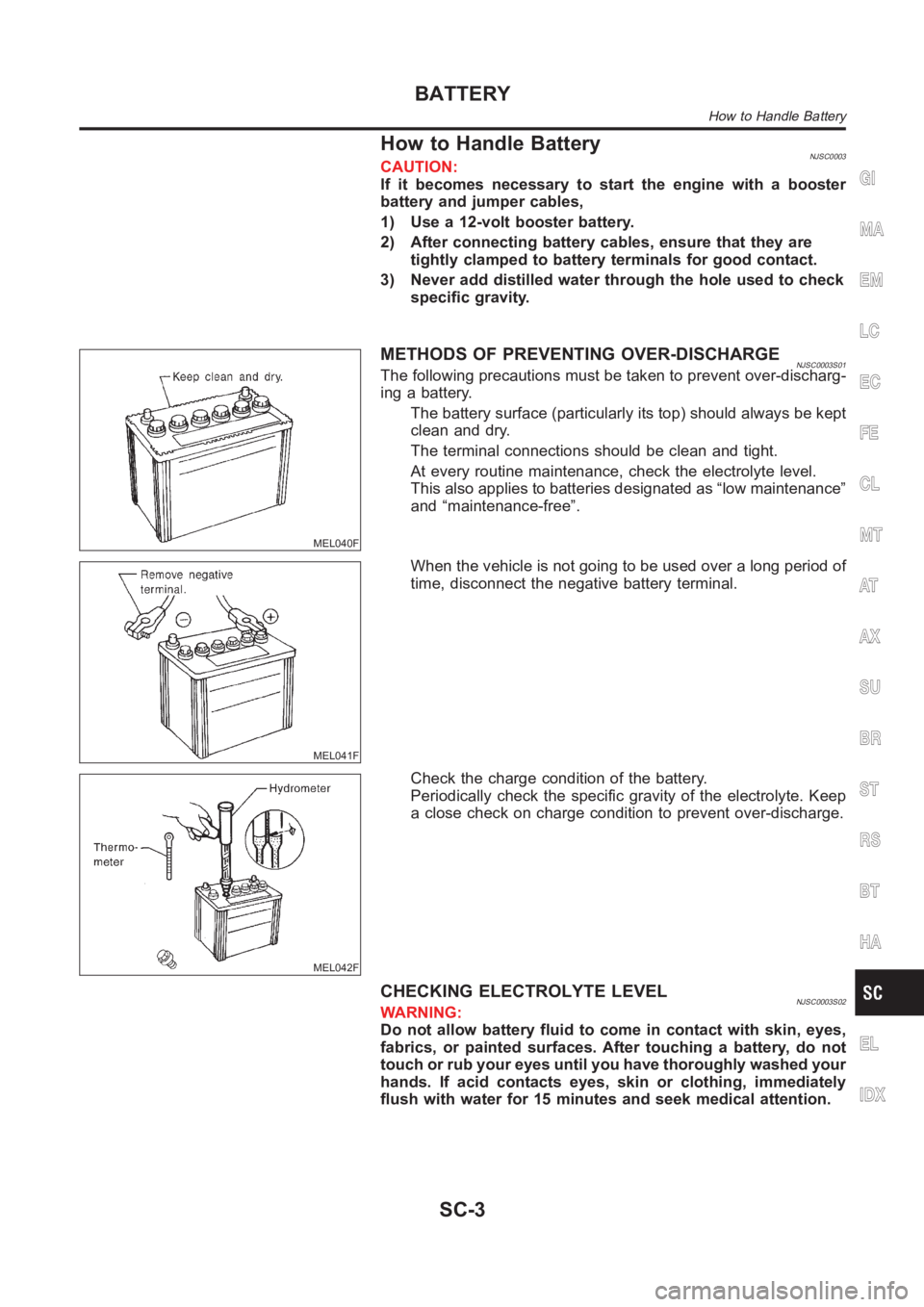
The battery surface (particularly its top) should always be kept
clean and dry.
The terminal connections should be clean and tight.
At every routine maintenance, check the electrolyte level.
This also applies to batteries designated as “low maintenance”
and “maintenance-free”.
MEL041F
When the vehicle is not going to be used over a long period of
time, disconnect the negative battery terminal.
MEL042F
Check the charge condition of the battery.
Periodically check the specific gravity of the electrolyte. Keep
a close check on charge condition to prevent over-discharge.
CHECKING ELECTROLYTE LEVELNJSC0003S02WARNING:
Do not allow battery fluid to come in contact with skin, eyes,
fabrics, or painted surfaces. After touching a battery, do not
touch or rub your eyes until you have thoroughly washed your
hands. If acid contacts eyes, skin or clothing, immediately
flush with water for 15 minutes and seek medical attention.
GI
MA
EM
LC
EC
FE
CL
MT
AT
AX
SU
BR
ST
RS
BT
HA
EL
IDX
BATTERY
How to Handle Battery
SC-3
Page 3110 of 3189
MEL043F
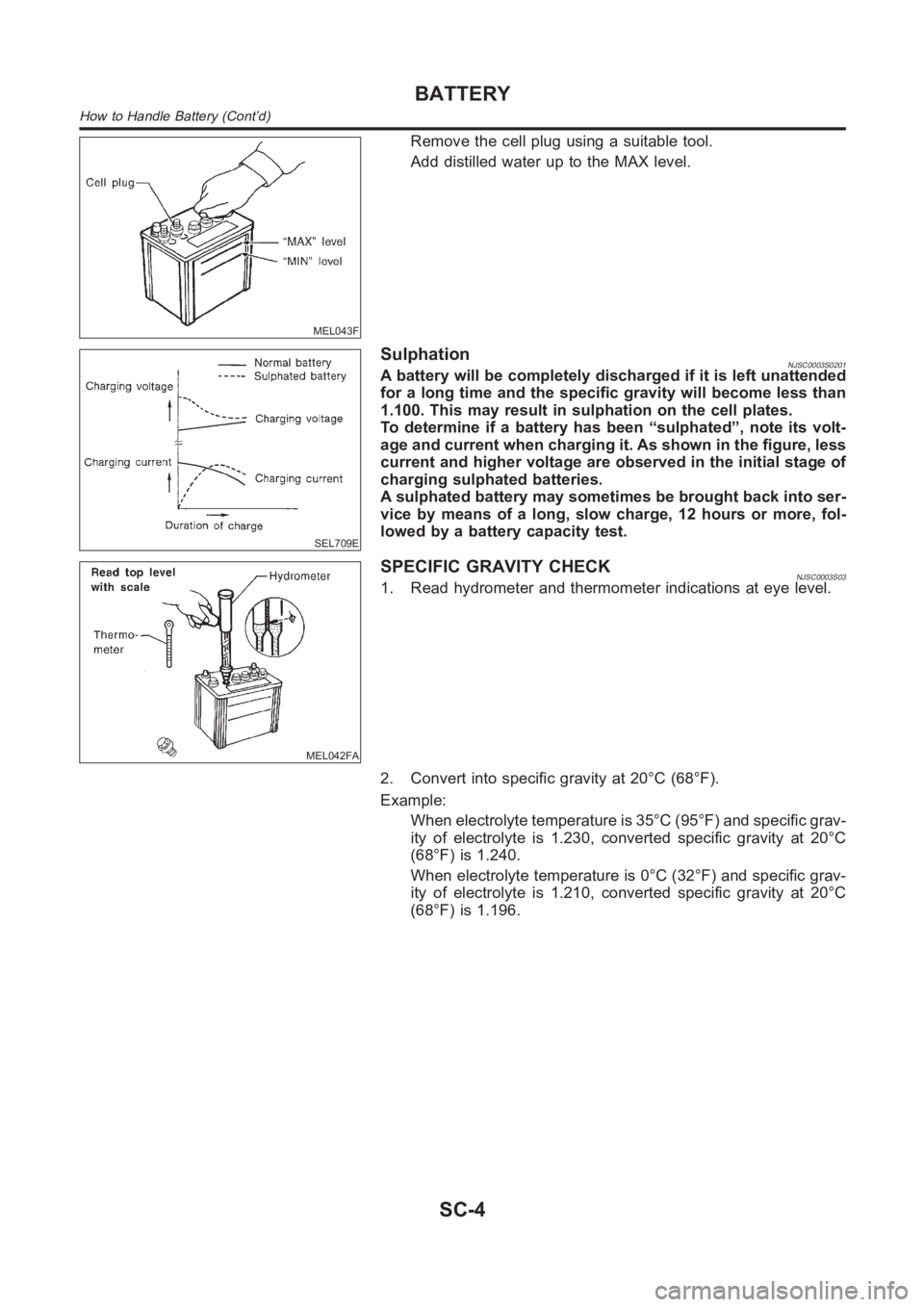
Remove the cell plug using a suitable tool.
Add distilled water up to the MAX level.
SEL709E
SulphationNJSC0003S0201A battery will be completely discharged if it is left unattended
for a long time and the specific gravity will become less than
1.100. This may result in sulphation on the cell plates.
To determine if a battery has been “sulphated”, note its volt-
age and current when charging it. As shown in the figure, less
current and higher voltage are observed in the initial stage of
charging sulphated batteries.
A sulphated battery may sometimes be brought back into ser-
vice by means of a long, slow charge, 12 hours or more, fol-
lowed by a battery capacity test.
MEL042FA
SPECIFIC GRAVITY CHECKNJSC0003S031. Read hydrometer and thermometer indications at eye level.
2. Convert into specific gravity at 20°C (68°F).
Example:
When electrolyte temperature is 35°C (95°F) and specific grav-
ity of electrolyte is 1.230, converted specific gravity at 20°C
(68°F) is 1.240.
When electrolyte temperature is 0°C (32°F) and specific grav-
ity of electrolyte is 1.210, converted specific gravity at 20°C
(68°F) is 1.196.
BATTERY
How to Handle Battery (Cont’d)
SC-4
Page 3118 of 3189
![NISSAN ALMERA N16 2003 Electronic Repair Manual Fig. 6 INITIAL CHARGING CURRENT SETTING AND CHARGING TIME (Quick charge)
BATTERY
TYPE
28B19R(L)
34B19R(L)
46B24R(L)
55B24R(L)
50D23R(L)
55D23R(L)
65D26R(L)
80D26R(L)
025 [YUASA type code]
027 [YUASA t](/img/5/57350/w960_57350-3117.png "NISSAN ALMERA N16 2003 Electronic Repair Manual Fig. 6 INITIAL CHARGING CURRENT SETTING AND CHARGING TIME (Quick charge)
BATTERY
TYPE
28B19R(L)
34B19R(L)
46B24R(L)
55B24R(L)
50D23R(L)
55D23R(L)
65D26R(L)
80D26R(L)
025 [YUASA type code]
027 [YUASA t")
Fig. 6 INITIAL CHARGING CURRENT SETTING AND CHARGING TIME (Quick charge)
BATTERY
TYPE
28B19R(L)
34B19R(L)
46B24R(L)
55B24R(L)
50D23R(L)
55D23R(L)
65D26R(L)
80D26R(L)
025 [YUASA type code]
027 [YUASA type code]
063 [YUASA type code]
067 [YUASA type code]
096 [YUASA type code]
065 [YUASA type code]
075 [YUASA type code]
096L [YUASA type code]
010S [YUASA type code]
75D31R(L)
95D31R(L)
115D31R(L)
110D26R(L)
95E41R(L)
130E41R(L)
CURRENT
[A]10 (A) 15 (A) 20 (A) 25 (A) 30 (A)40
(A)
CONVERTED SPECIFIC GRAVITY
1.100 -
1.1302.5 hours
1.130 -
1.1602.0 hours
1.160 -
1.1901.5 hours
1.190 -
1.2201.0 hours
Above
1.2200.75 hours (45 min.)
Check battery type and determine the specified current using the table shown above.
After starting charging, adjustment of charging current is not necessary.
CAUTION:
Do not use quick charge method on a battery whose specific gravity is less than 1.100.
Set initial charging current to value specified in Fig. 6. If charger is notcapable of producing
specified current value, set its charging current as close to that value aspossible.
Keep battery away from open flame while it is being charged.
When connecting charger, connect leads first, then turn on charger. Do notturn on charger first,
as this may cause a spark.
Be careful of a rise in battery temperature because a large current flow is required during quick-
charge operation.
If battery temperature rises above 60°C (140°F), stop charging. Always charge battery when its
temperature is below 60°C (140°F).
Do not exceed the charging time specified in Fig. 6, because charging battery over the charging
time can cause deterioration of the battery.
BATTERY
Battery Test and Charging Chart (Cont’d)
SC-12
Page 3119 of 3189
System DescriptionNJSC0004M/T MODELSNJSC0004S01Power is supplied at all times
through 40A fusible link (letterB, located in the fuse and fusible link box)
to ignition switch terminal 1.
With the ignition switch in START position, power is supplied
from ignition switch terminal 5
to smart entrance control unit terminal 58
from smart entrance control unit terminal 59
to starter motor harness connector terminal 1.
The starter motor plunger closes and provides a closed circuit between thebattery and starter motor. The
starter motor is grounded to the engine block. With power and ground supplied, cranking occurs and the engine
starts.
A/T MODELSNJSC0004S02Power is supplied at all times
through 40A fusible link (letterB, located in the fuse and fusible link box)
to ignition switch terminal 1.
With the ignition switch in the START position, power is supplied
from ignition switch terminal 5
to park/neutral position relay terminal 5.
With the ignition switch ON or START position, power is supplied
through 10A fuse [No. 20, located in the fuse block (J/B)]
to park/neutral position (PNP) relay terminal 1.
With the selector lever in the P or N position, ground is supplied
to park/neutral position relay terminal 2 through the park/neutral position switch
to smart entrance control unit terminal 59
from smart entrance control unit terminal 58
from body grounds, F9 and F10.
Then park/neutral position relay is energized and power is supplied
from park/neutral position relay terminal 3
to starter motor harness connector terminal 1.
The starter motor plunger closes and provides a closed circuit between thebattery and starter motor. The
starter motor is grounded to the engine block. With power and ground supplied, cranking occurs and the engine
starts.
GI
MA
EM
LC
EC
FE
CL
MT
AT
AX
SU
BR
ST
RS
BT
HA
EL
IDX
STARTING SYSTEM
System Description
SC-13
Page 3133 of 3189
System DescriptionNJSC0009The alternator provides DC voltage to operate the vehicle’s electrical system and to keep the battery charged.
The voltage output is controlled by the IC regulator.
Power is supplied at all times to alternator terminal 4 (S) through:
10A fuse (No. 39, located in the fuse and fusible link box).
Terminal B supplies power to charge the battery and operate the vehicle’s electrical system. Output voltage
is controlled by the IC regulator at terminal 4 (S) detecting the input voltage. The charging circuit is protected
by the 100A fusible link.
The alternator is grounded to the engine block.
With the ignition switch in the ON or START position, power is supplied
through 10A fuse [No. 30, located in the fuse block (J/B)]
to combination meter terminal 30
Ground is supplied to terminal 18 of the combination meter through terminal 3 (L) of the alternator. With power
and ground supplied, the charge warning lamp will illuminate. When the alternator is providing sufficient volt-
age with the engine running, the ground is opened and the charge warning lamp will go off.
If the charge warning lamp illuminates with the engine running, a fault is indicated.GI
MA
EM
LC
EC
FE
CL
MT
AT
AX
SU
BR
ST
RS
BT
HA
EL
IDX
CHARGING SYSTEM
System Description
SC-27
Page 3151 of 3189
Checking and Adjusting Drive BeltsNJST0011Refer to EM-11 (QG) or EM-11 (YD), “Checking Drive Belts”.
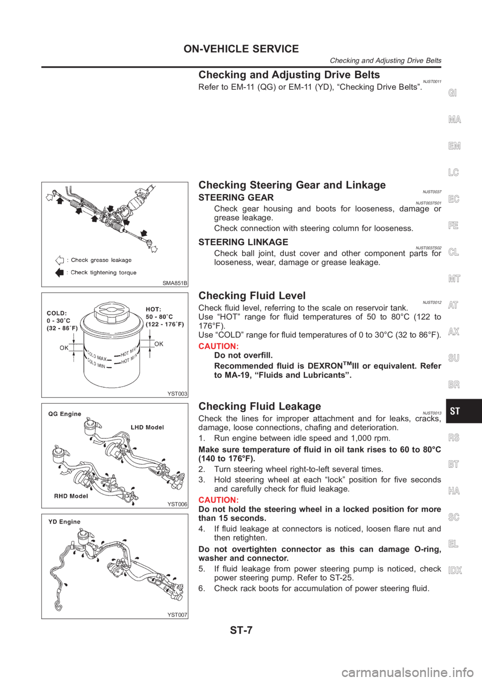
SMA851B
Checking Steering Gear and LinkageNJST0037STEERING GEARNJST0037S01Check gear housing and boots for looseness, damage or
grease leakage.
Check connection with steering column for looseness.
STEERING LINKAGENJST0037S02Check ball joint, dust cover and other component parts for
looseness, wear, damage or grease leakage.
YST003
Checking Fluid LevelNJST0012Check fluid level, referring to the scale on reservoir tank.
Use “HOT” range for fluid temperatures of 50 to 80°C (122 to
176°F).
Use “COLD” range for fluid temperatures of 0 to 30°C (32 to 86°F).
CAUTION:
Do not overfill.
Recommended fluid is DEXRONTMIII or equivalent. Refer
to MA-19, “Fluids and Lubricants”.
YST006
YST007
Checking Fluid LeakageNJST0013Check the lines for improper attachment and for leaks, cracks,
damage, loose connections, chafing and deterioration.
1. Run engine between idle speed and 1,000 rpm.
Make sure temperature of fluid in oil tank rises to 60 to 80°C
(140 to 176°F).
2. Turn steering wheel right-to-left several times.
3. Hold steering wheel at each “lock” position for five seconds
and carefully check for fluid leakage.
CAUTION:
Do not hold the steering wheel in a locked position for more
than 15 seconds.
4. If fluid leakage at connectors is noticed, loosen flare nut and
then retighten.
Do not overtighten connector as this can damage O-ring,
washer and connector.
5. If fluid leakage from power steering pump is noticed, check
power steering pump. Refer to ST-25.
6. Check rack boots for accumulation of power steering fluid.
GI
MA
EM
LC
EC
FE
CL
MT
AT
AX
SU
BR
RS
BT
HA
SC
EL
IDX
ON-VEHICLE SERVICE
Checking and Adjusting Drive Belts
ST-7
Page 3166 of 3189
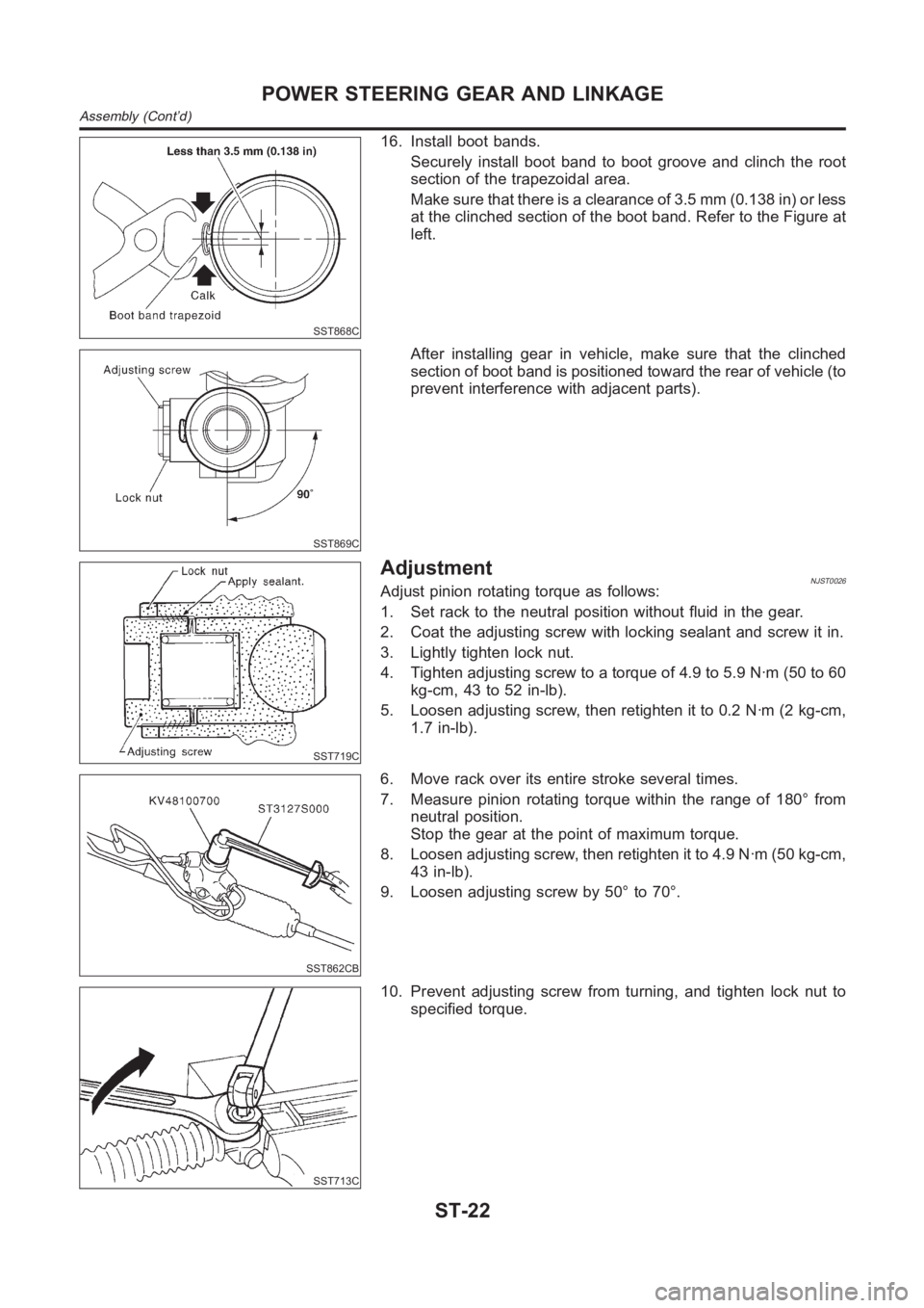
SST868C
16. Install boot bands.
Securely install boot band to boot groove and clinch the root
section of the trapezoidal area.
Make sure that there is a clearance of 3.5 mm (0.138 in) or less
at the clinched section of the boot band. Refer to the Figure at
left.
SST869C
After installing gear in vehicle, make sure that the clinched
section of boot band is positioned toward the rear of vehicle (to
prevent interference with adjacent parts).
SST719C
AdjustmentNJST0026Adjust pinion rotating torque as follows:
1. Set rack to the neutral position without fluid in the gear.
2. Coat the adjusting screw with locking sealant and screw it in.
3. Lightly tighten lock nut.
4. Tighten adjusting screw to a torque of 4.9 to 5.9 N·m (50 to 60
kg-cm, 43 to 52 in-lb).
5. Loosen adjusting screw, then retighten it to 0.2 N·m (2 kg-cm,
1.7 in-lb).
SST862CB
6. Move rack over its entire stroke several times.
7. Measure pinion rotating torque within the range of 180° from
neutral position.
Stop the gear at the point of maximum torque.
8. Loosen adjusting screw, then retighten it to 4.9 N·m (50 kg-cm,
43 in-lb).
9. Loosen adjusting screw by 50° to 70°.
SST713C
10. Prevent adjusting screw from turning, and tighten lock nut to
specified torque.
POWER STEERING GEAR AND LINKAGE
Assembly (Cont’d)
ST-22
Page 3178 of 3189
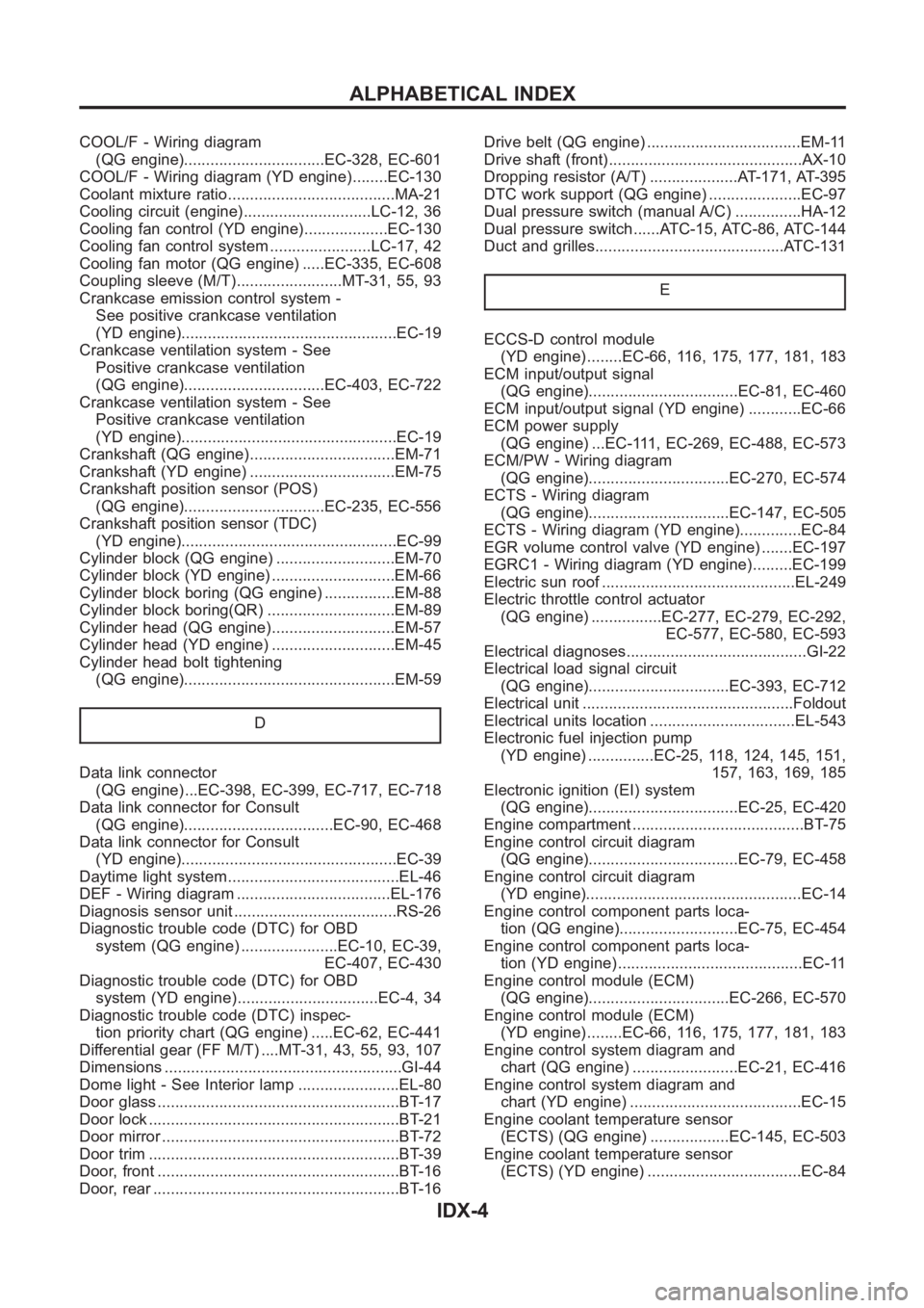
COOL/F - Wiring diagram
(QG engine)................................EC-328, EC-601
COOL/F - Wiring diagram (YD engine) ........EC-130
Coolant mixture ratio......................................MA-21
Cooling circuit (engine).............................LC-12, 36
Cooling fan control (YD engine)...................EC-130
Cooling fan control system .......................LC-17, 42
Cooling fan motor (QG engine) .....EC-335, EC-608
Coupling sleeve (M/T)........................MT-31, 55, 93
Crankcase emission control system -
See positive crankcase ventilation
(YD engine).................................................EC-19
Crankcase ventilation system - See
Positive crankcase ventilation
(QG engine)................................EC-403, EC-722
Crankcase ventilation system - See
Positive crankcase ventilation
(YD engine).................................................EC-19
Crankshaft (QG engine).................................EM-71
Crankshaft (YD engine) .................................EM-75
Crankshaft position sensor (POS)
(QG engine)................................EC-235, EC-556
Crankshaft position sensor (TDC)
(YD engine).................................................EC-99
Cylinder block (QG engine) ...........................EM-70
Cylinder block (YD engine) ............................EM-66
Cylinder block boring (QG engine) ................EM-88
Cylinder block boring(QR) .............................EM-89
Cylinder head (QG engine)............................EM-57
Cylinder head (YD engine) ............................EM-45
Cylinder head bolt tightening
(QG engine)................................................EM-59
D
Data link connector
(QG engine) ...EC-398, EC-399, EC-717, EC-718
Data link connector for Consult
(QG engine)..................................EC-90, EC-468
Data link connector for Consult
(YD engine).................................................EC-39
Daytime light system.......................................EL-46
DEF - Wiring diagram ...................................EL-176
Diagnosis sensor unit .....................................RS-26
Diagnostic trouble code (DTC) for OBD
system (QG engine) ......................EC-10, EC-39,
EC-407, EC-430
Diagnostic trouble code (DTC) for OBD
system (YD engine) ................................EC-4, 34
Diagnostic trouble code (DTC) inspec-
tion priority chart (QG engine) .....EC-62, EC-441
Differential gear (FF M/T) ....MT-31, 43, 55, 93, 107
Dimensions <0011001100110011001100110011001100110011001100110011001100110011001100110011001100110011001100110011001100110011001100110011001100110011001100110011001100110011001100110011001100110011001100110011001100
1100110011[.GI-44
Dome light - See Interior lamp .......................EL-80
Door glass <0011001100110011001100110011001100110011001100110011001100110011001100110011001100110011001100110011001100110011001100110011001100110011001100110011001100110011001100110011001100110011001100110011001100
11001100110011[.BT-17
Door lock <0011001100110011001100110011001100110011001100110011001100110011001100110011001100110011001100110011001100110011001100110011001100110011001100110011001100110011001100110011001100110011001100110011001100
110011001100110011[..BT-21
Door mirror <0011001100110011001100110011001100110011001100110011001100110011001100110011001100110011001100110011001100110011001100110011001100110011001100110011001100110011001100110011001100110011001100110011001100
1100110011[.BT-72
Door trim <0011001100110011001100110011001100110011001100110011001100110011001100110011001100110011001100110011001100110011001100110011001100110011001100110011001100110011001100110011001100110011001100110011001100
110011001100110011[..BT-39
Door, front <0011001100110011001100110011001100110011001100110011001100110011001100110011001100110011001100110011001100110011001100110011001100110011001100110011001100110011001100110011001100110011001100110011001100
1100110011[..BT-16
Door, rear <0011001100110011001100110011001100110011001100110011001100110011001100110011001100110011001100110011001100110011001100110011001100110011001100110011001100110011001100110011001100110011001100110011001100
11001100110011[..BT-16Drive belt (QG engine) ...................................EM-11
Drive shaft (front)............................................AX-10
Dropping resistor (A/T) ....................AT-171, AT-395
DTC work support (QG engine) .....................EC-97
Dual pressure switch (manual A/C) ...............HA-12
Dual pressure switch ......ATC-15, ATC-86, ATC-144
Duct and grilles...........................................ATC-131
E
ECCS-D control module
(YD engine) ........EC-66, 116, 175, 177, 181, 183
ECM input/output signal
(QG engine)..................................EC-81, EC-460
ECM input/output signal (YD engine) ............EC-66
ECM power supply
(QG engine) ...EC-111, EC-269, EC-488, EC-573
ECM/PW - Wiring diagram
(QG engine)................................EC-270, EC-574
ECTS - Wiring diagram
(QG engine)................................EC-147, EC-505
ECTS - Wiring diagram (YD engine)..............EC-84
EGR volume control valve (YD engine) .......EC-197
EGRC1 - Wiring diagram (YD engine) .........EC-199
Electric sun roof ............................................EL-249
Electric throttle control actuator
(QG engine) ................EC-277, EC-279, EC-292,
EC-577, EC-580, EC-593
Electrical diagnoses.........................................GI-22
Electrical load signal circuit
(QG engine)................................EC-393, EC-712
Electrical unit ................................................Foldout
Electrical units location .................................EL-543
Electronic fuel injection pump
(YD engine) ...............EC-25, 118, 124, 145, 151,
157, 163, 169, 185
Electronic ignition (EI) system
(QG engine)..................................EC-25, EC-420
Engine compartment .......................................BT-75
Engine control circuit diagram
(QG engine)..................................EC-79, EC-458
Engine control circuit diagram
(YD engine).................................................EC-14
Engine control component parts loca-
tion (QG engine)...........................EC-75, EC-454
Engine control component parts loca-
tion (YD engine) ..........................................EC-11
Engine control module (ECM)
(QG engine)................................EC-266, EC-570
Engine control module (ECM)
(YD engine) ........EC-66, 116, 175, 177, 181, 183
Engine control system diagram and
chart (QG engine) ........................EC-21, EC-416
Engine control system diagram and
chart (YD engine) .......................................EC-15
Engine coolant temperature sensor
(ECTS) (QG engine) ..................EC-145, EC-503
Engine coolant temperature sensor
(ECTS) (YD engine) ...................................EC-84
ALPHABETICAL INDEX
IDX-4