trunk release NISSAN ALMERA N16 2003 Electronic Repair Manual
[x] Cancel search | Manufacturer: NISSAN, Model Year: 2003, Model line: ALMERA N16, Model: NISSAN ALMERA N16 2003Pages: 3189, PDF Size: 54.76 MB
Page 19 of 3189

AGI070
HARNESS INDICATIONNJGI0003S0202Letter designations next to test meter probe indicate harness
(connector) wire color.
Connector numbers in a single circle M33 indicate harness
connectors.
COMPONENT INDICATIONNJGI0003S0203Connector numbers in a double circle F211 indicate compo-
nent connectors.
SGI860
SWITCH POSITIONSNJGI0003S0204Switches are shown in wiring diagrams as if the vehicle is in the
“normal” condition.
A vehicle is in the “normal” condition when:
ignition switch is “OFF”,
doors, hood and trunk lid/back door are closed,
pedals are not depressed, and
parking brake is released.
MA
EM
LC
EC
FE
CL
MT
AT
AX
SU
BR
ST
RS
BT
HA
SC
EL
IDX
HOW TO READ WIRING DIAGRAMS
Description (Cont’d)
GI-17
Page 59 of 3189
NJMA0004
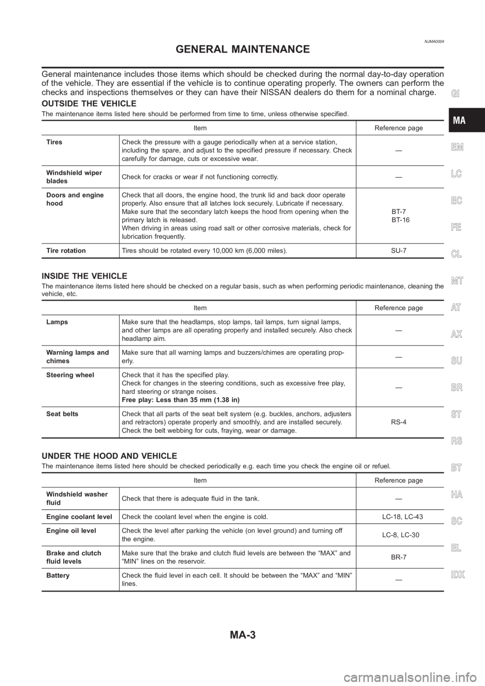
General maintenance includes those items which should be checked during the normal day-to-day operation
of the vehicle. They are essential if the vehicle is to continue operating properly. The owners can perform the
checks and inspections themselves or they can have their NISSAN dealers dothem for a nominal charge.
OUTSIDE THE VEHICLE
The maintenance items listed here should be performed from time to time, unless otherwise specified.
Item Reference page
TiresCheck the pressure with a gauge periodically when at a service station,
including the spare, and adjust to the specified pressure if necessary. Check
carefully for damage, cuts or excessive wear.—
Windshield wiper
bladesCheck for cracks or wear if not functioning correctly. —
Doors and engine
hoodCheck that all doors, the engine hood, the trunk lid and back door operate
properly. Also ensure that all latches lock securely. Lubricate if necessary.
Make sure that the secondary latch keeps the hood from opening when the
primary latch is released.
When driving in areas using road salt or other corrosive materials, check for
lubrication frequently.BT-7
BT-16
Tire rotationTires should be rotated every 10,000 km (6,000 miles). SU-7
INSIDE THE VEHICLE
The maintenance items listed here should be checked on a regular basis, such as when performing periodic maintenance, cleaning the
vehicle, etc.
Item Reference page
LampsMake sure that the headlamps, stop lamps, tail lamps, turn signal lamps,
and other lamps are all operating properly and installed securely. Also check
headlamp aim.—
Warning lamps and
chimesMake sure that all warning lamps and buzzers/chimes are operating prop-
erly.—
Steering wheelCheck that it has the specified play.
Check for changes in the steering conditions, such as excessive free play,
hard steering or strange noises.
Free play: Less than 35 mm (1.38 in)—
Seat beltsCheck that all parts of the seat belt system (e.g. buckles, anchors, adjusters
and retractors) operate properly and smoothly, and are installed securely.
Check the belt webbing for cuts, fraying, wear or damage.RS-4
UNDER THE HOOD AND VEHICLE
The maintenance items listed here should be checked periodically e.g. each time you check the engine oil or refuel.
Item Reference page
Windshield washer
fluidCheck that there is adequate fluid in the tank. —
Engine coolant levelCheck the coolant level when the engine is cold. LC-18, LC-43
Engine oil levelCheck the level after parking the vehicle (on level ground) and turning off
the engine.LC-8, LC-30
Brake and clutch
fluid levelsMake sure that the brake and clutch fluid levels are between the “MAX” and
“MIN” lines on the reservoir.BR-7
BatteryCheck the fluid level in each cell. It should be between the “MAX” and “MIN”
lines.—
GI
EM
LC
EC
FE
CL
MT
AT
AX
SU
BR
ST
RS
BT
HA
SC
EL
IDX
GENERAL MAINTENANCE
MA-3
Page 2607 of 3189
SIIA1645E
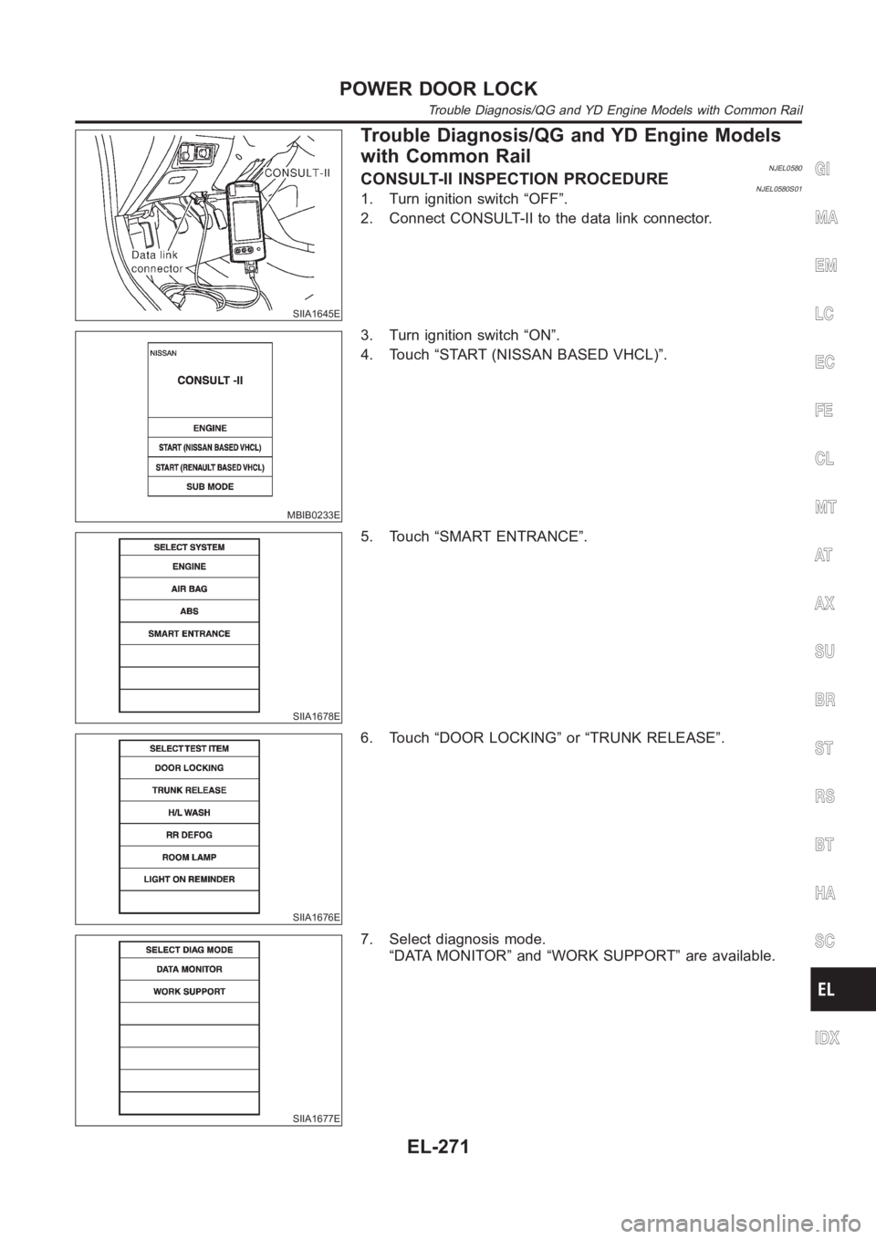
Trouble Diagnosis/QG and YD Engine Models
with Common Rail
NJEL0580CONSULT-II INSPECTION PROCEDURENJEL0580S011. Turn ignition switch “OFF”.
2. Connect CONSULT-II to the data link connector.
MBIB0233E
3. Turn ignition switch “ON”.
4. Touch “START (NISSAN BASED VHCL)”.
SIIA1678E
5. Touch “SMART ENTRANCE”.
SIIA1676E
6. Touch “DOOR LOCKING” or “TRUNK RELEASE”.
SIIA1677E
7. Select diagnosis mode.
“DATA MONITOR” and “WORK SUPPORT” are available.
GI
MA
EM
LC
EC
FE
CL
MT
AT
AX
SU
BR
ST
RS
BT
HA
SC
IDX
POWER DOOR LOCK
Trouble Diagnosis/QG and YD Engine Models with Common Rail
EL-271
Page 2608 of 3189
![NISSAN ALMERA N16 2003 Electronic Repair Manual CONSULT-II APPLICATION ITEMSNJEL0580S02Door LockingNJEL0580S0201DATA MONITOR
Monitored Item Description
IGNITION SW Indicates [ON/OFF] condition of ignition switch.
KEY IN DETECT Indicates [ON/OFF] co NISSAN ALMERA N16 2003 Electronic Repair Manual CONSULT-II APPLICATION ITEMSNJEL0580S02Door LockingNJEL0580S0201DATA MONITOR
Monitored Item Description
IGNITION SW Indicates [ON/OFF] condition of ignition switch.
KEY IN DETECT Indicates [ON/OFF] co](/img/5/57350/w960_57350-2607.png)
CONSULT-II APPLICATION ITEMSNJEL0580S02Door LockingNJEL0580S0201DATA MONITOR
Monitored Item Description
IGNITION SW Indicates [ON/OFF] condition of ignition switch.
KEY IN DETECT Indicates [ON/OFF] condition of key switch.
DOOR SW DR RR Indicates [ON/OFF] condition of rear door switch (driver side).
DOOR SW AS RR Indicates [ON/OFF] condition of rear door switch (passenger side).
AS DOOR SW Indicates [ON/OFF] condition of front door switch (passenger side).
DR DOOR SW Indicates [ON\OFF] condition of front door switch (driver side).
CDL LOCK SW Indicates [ON/OFF] condition of lock signal from door lock/ unlock switch.
CDL UNLOCK SW Indicates [ON/OFF] condition of unlock signal from door lock/ unlock switch.
RKE LOCK Indicates [ON/OFF] condition of lock signal from remote controller.
RKE UNLOCK Indicates [ON/OFF] condition of unlock signal from remote controller.
RKE SEL UNLOCK Indicates [ON/OFF] condition of select unlock signal from remote controller.
WORK SUPPORT
Monitored Item Description
AUTO RE-LOCKAuto re-lock function can be changed in this mode. The re-lock mode will be changed when
“CHANGE MODE” on CONSULT-II screen is touched.
SELECTIVE UNLOCKSelective unlock function can be changed in this mode. The unlock mode willbe changed when
“CHANGE SET” on CONSULT-II screen is touched.
Trunk ReleaseNJEL0580S0202DATA MONITOR
Monitored Item Description
IGNITION SW Indicates [ON/OFF] condition of ignition switch.
TRUNK OPEN SW Indicates [ON/OFF] condition of trunk room lamp switch (sedan) or back door switch (wagon).
INT TRUNK RELIndicates [ON/OFF] condition of internal trunk release switch (sedan) orinternal back door
release switch (wagon).
EXT TRUNK RELIndicates [ON/OFF] condition of external trunk release switch (sedan) orexternal back door
release switch (wagon).
RKE TRUNK RELIndicates [ON/OFF] condition of trunk (sedan) or back door (back door) open signal from trunk
or back door release switch.
WORK SUPPORT
Monitored Item Description
TRUNK OPEN DELAYThis mode can be changed trunk release switch (sedan) or back door (wagon) release switch
operation time.
POWER DOOR LOCK
Trouble Diagnosis/QG and YD Engine Models with Common Rail (Cont’d)
EL-272
Page 2609 of 3189
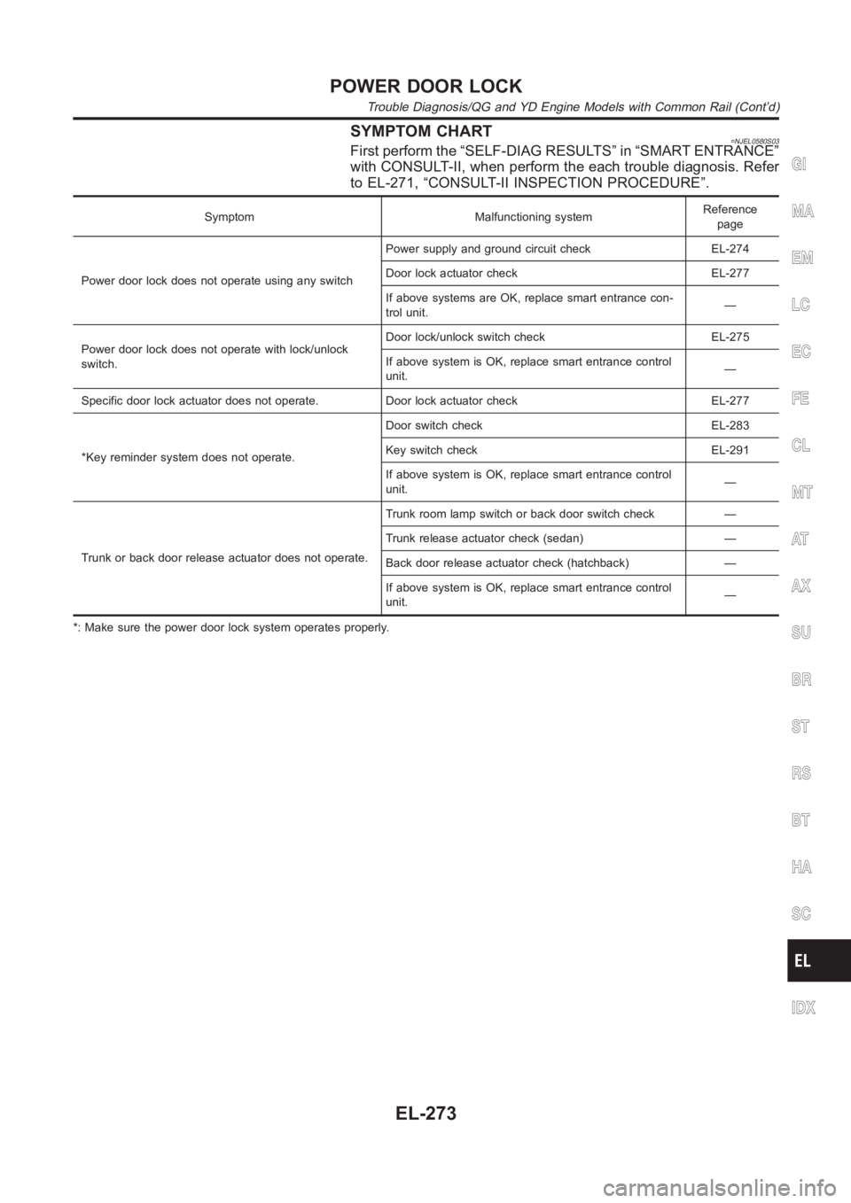
SYMPTOM CHART=NJEL0580S03First perform the “SELF-DIAG RESULTS” in “SMART ENTRANCE”
with CONSULT-II, when perform the each trouble diagnosis. Refer
to EL-271, “CONSULT-II INSPECTION PROCEDURE”.
Symptom Malfunctioning systemReference
page
Power door lock does not operate using any switchPower supply and ground circuit check EL-274
Door lock actuator check EL-277
If above systems are OK, replace smart entrance con-
trol unit.—
Power door lock does not operate with lock/unlock
switch.Door lock/unlock switch check EL-275
If above system is OK, replace smart entrance control
unit.—
Specific door lock actuator does not operate. Door lock actuator check EL-277
*Key reminder system does not operate.Door switch check EL-283
Key switch check EL-291
If above system is OK, replace smart entrance control
unit.—
Trunk or back door release actuator does not operate.Trunk room lamp switch or back door switch check —
Trunk release actuator check (sedan) —
Back door release actuator check (hatchback) —
If above system is OK, replace smart entrance control
unit.—
*: Make sure the power door lock system operates properly.
GI
MA
EM
LC
EC
FE
CL
MT
AT
AX
SU
BR
ST
RS
BT
HA
SC
IDX
POWER DOOR LOCK
Trouble Diagnosis/QG and YD Engine Models with Common Rail (Cont’d)
EL-273
Page 2649 of 3189
SIIA1645E
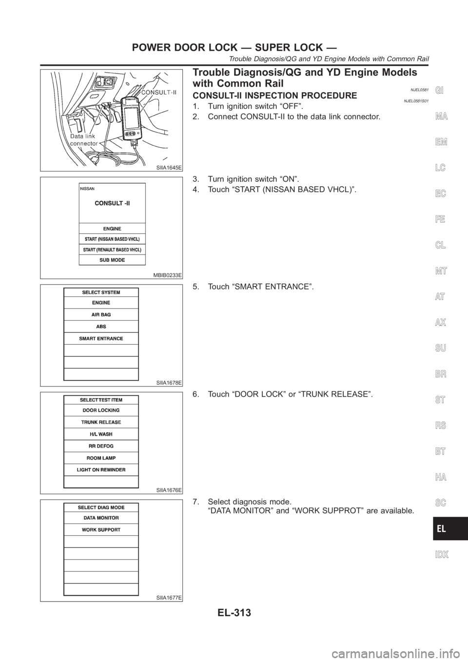
Trouble Diagnosis/QG and YD Engine Models
with Common Rail
NJEL0581CONSULT-II INSPECTION PROCEDURENJEL0581S011. Turn ignition switch “OFF”.
2. Connect CONSULT-II to the data link connector.
MBIB0233E
3. Turn ignition switch “ON”.
4. Touch “START (NISSAN BASED VHCL)”.
SIIA1678E
5. Touch “SMART ENTRANCE”.
SIIA1676E
6. Touch “DOOR LOCK” or “TRUNK RELEASE”.
SIIA1677E
7. Select diagnosis mode.
“DATA MONITOR” and “WORK SUPPROT” are available.
GI
MA
EM
LC
EC
FE
CL
MT
AT
AX
SU
BR
ST
RS
BT
HA
SC
IDX
POWER DOOR LOCK — SUPER LOCK —
Trouble Diagnosis/QG and YD Engine Models with Common Rail
EL-313
Page 2650 of 3189
![NISSAN ALMERA N16 2003 Electronic Repair Manual CONSULT-II APPLICATION ITEMSNJEL0581S02Door LockingNJEL0581S0201DATA MONITOR
Monitored Item Description
IGNITION SW Indicates [ON/OFF] condition of ignition switch.
KEY IN DETECT Indicates [ON/OFF] co NISSAN ALMERA N16 2003 Electronic Repair Manual CONSULT-II APPLICATION ITEMSNJEL0581S02Door LockingNJEL0581S0201DATA MONITOR
Monitored Item Description
IGNITION SW Indicates [ON/OFF] condition of ignition switch.
KEY IN DETECT Indicates [ON/OFF] co](/img/5/57350/w960_57350-2649.png)
CONSULT-II APPLICATION ITEMSNJEL0581S02Door LockingNJEL0581S0201DATA MONITOR
Monitored Item Description
IGNITION SW Indicates [ON/OFF] condition of ignition switch.
KEY IN DETECT Indicates [ON/OFF] condition of key switch.
DOOR SW DR RR Indicates [ON/OFF] condition of rear door switch (driver side).
DOOR SW AS RR Indicates [ON/OFF] condition of rear door switch (passenger side).
AS DOOR SW Indicates [ON/OFF] condition of front door switch (passenger side).
DR DOOR SW Indicates [ON\OFF] condition of front door switch (driver side).
CDL LOCK SW Indicates [ON/OFF] condition of lock signal from door lock/ unlock switch.
CDL UNLOCK SW Indicates [ON/OFF] condition of unlock signal from door lock/ unlock switch.
RKE LOCK Indicates [ON/OFF] condition of lock signal from remote controller.
RKE UNLOCK Indicates [ON/OFF] condition of unlock signal from remote controller.
RKE SEL UNLOCK Indicates [ON/OFF] condition of select unlock signal from remote controller.
WORK SUPPORT
Monitored Item Description
AUTO RE-LOCKAuto re-lock function can be changed in this mode. The re-lock mode will be changed when
“CHANGE MODE” on CONSULT-II screen is touched.
SELECTIVE UNLOCKSelective unlock function can be changed in this mode. The unlock mode willbe changed when
“CHANGE SET” on CONSULT-II screen is touched.
Trunk ReleaseNJEL0581S0202DATA MONITOR
Monitored Item Description
IGNITION SW Indicates [ON/OFF] condition of ignition switch.
TRUNK OPEN SW Indicates [ON/OFF] condition of trunk room lamp switch (sedan) or back door switch (wagon).
INT TRUNK RELIndicates [ON/OFF] condition of internal trunk release switch (sedan) orinternal back door
release switch (wagon).
EXT TRUNK RELIndicates [ON/OFF] condition of external trunk release switch (sedan) orexternal back door
release switch (wagon).
RKE TRUNK RELIndicates [ON/OFF] condition of trunk (sedan) or back door (back door) open signal from trunk
or back door release switch.
WORK SUPPORT
Monitored Item Description
TRUNK OPEN DELAYThis mode can be changed trunk release switch (sedan) or back door (wagon) release switch
operation time.
POWER DOOR LOCK — SUPER LOCK —
Trouble Diagnosis/QG and YD Engine Models with Common Rail (Cont’d)
EL-314
Page 2652 of 3189
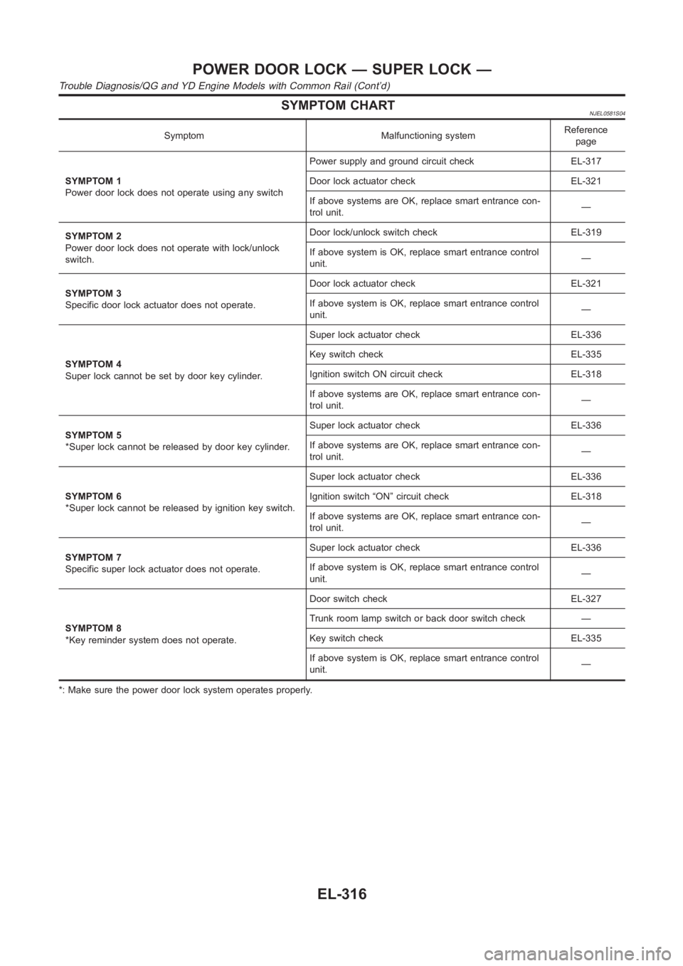
SYMPTOM CHARTNJEL0581S04
Symptom Malfunctioning systemReference
page
SYMPTOM 1
Power door lock does not operate using any switchPower supply and ground circuit check EL-317
Door lock actuator check EL-321
If above systems are OK, replace smart entrance con-
trol unit.—
SYMPTOM 2
Power door lock does not operate with lock/unlock
switch.Door lock/unlock switch check EL-319
If above system is OK, replace smart entrance control
unit.—
SYMPTOM 3
Specific door lock actuator does not operate.Door lock actuator check EL-321
If above system is OK, replace smart entrance control
unit.—
SYMPTOM 4
Super lock cannot be set by door key cylinder.Super lock actuator check EL-336
Key switch check EL-335
Ignition switch ON circuit check EL-318
If above systems are OK, replace smart entrance con-
trol unit.—
SYMPTOM 5
*Super lock cannot be released by door key cylinder.Super lock actuator check EL-336
If above systems are OK, replace smart entrance con-
trol unit.—
SYMPTOM 6
*Super lock cannot be released by ignition key switch.Super lock actuator check EL-336
Ignition switch “ON” circuit check EL-318
If above systems are OK, replace smart entrance con-
trol unit.—
SYMPTOM 7
Specific super lock actuator does not operate.Super lock actuator check EL-336
If above system is OK, replace smart entrance control
unit.—
SYMPTOM 8
*Key reminder system does not operate.Door switch check EL-327
Trunk room lamp switch or back door switch check —
Key switch check EL-335
If above system is OK, replace smart entrance control
unit.—
*: Make sure the power door lock system operates properly.
POWER DOOR LOCK — SUPER LOCK —
Trouble Diagnosis/QG and YD Engine Models with Common Rail (Cont’d)
EL-316
Page 2692 of 3189
![NISSAN ALMERA N16 2003 Electronic Repair Manual CONSULT-II APPLICATION ITEMSNJEL0582S02DATA MONITOR
Monitored Item Description
IGNITION SW Indicates [ON/OFF] condition of ignition switch in ON position.
TRUNK OPEN SW Indicates [ON/OFF] condition of NISSAN ALMERA N16 2003 Electronic Repair Manual CONSULT-II APPLICATION ITEMSNJEL0582S02DATA MONITOR
Monitored Item Description
IGNITION SW Indicates [ON/OFF] condition of ignition switch in ON position.
TRUNK OPEN SW Indicates [ON/OFF] condition of](/img/5/57350/w960_57350-2691.png)
CONSULT-II APPLICATION ITEMSNJEL0582S02DATA MONITOR
Monitored Item Description
IGNITION SW Indicates [ON/OFF] condition of ignition switch in ON position.
TRUNK OPEN SW Indicates [ON/OFF] condition of trunk room lamp switch (sedan) or back door switch (wagon).
RKE LOCK Indicates [ON/OFF] condition of lock signal from remote controller.
RKE UNLOCK Indicates [ON/OFF] condition of unlock signal from remote controller.
RKE SEL UNLOCK Indicates [ON/OFF] condition of select unlock signal from remote controller.
RKE TRUNK RELIndicates [ON/OFF] condition of trunk (sedan) or back door (wagon) open signal from trunk or
back door release switch.
BATTERY CHECK Indicates [OK/NG] condition of remote controller battery.
WORK SUPPORT
Test Item Description
KEYLESS CHECK It can be checked whether remote controller ID code is registered or not in this mode.
KEYLESS REGISTRATION Remote controller ID code can be registered.
KEYLESS DI FLASH This mode can be setting remote controller function.
SYMPTOM CHARTNJEL0582S03First perform the “SELF-DIAG RESULTS” in “SMART ENTRANCE”
with CONSULT-II, when perform the each trounble diagnosis. Refer
to EL-355, “CONSULT-II INSPECTION PROCEDURE”.
NOTE:
Always check remote controller battery before replacing
remote controller.
Symptom Diagnoses/service procedureReference
page
All function of multi-remote control system do not
operate.Remote controller battery check EL-357
Power supply and ground circuit for smart entrance control
unit checkEL-358
.If above systems are OK, replace smart entrance control unit. —
The new ID of remote controller cannot be
entered.Remote controller battery check EL-357
Key switch check —
Door switch check —
Power supply and ground circuit check EL-358
If above systems are OK, replace smart entrance control unit. —
Door lock or unlock does not function.If the power door lock system does not operate manually,
check power door lock system.EL-356
Remote controller battery check EL-357
If above systems are OK, replace smart entrance control unit. —
Hazard reminder does not activate properly
when pressing lock or unlock button of remote
controller.Remote controller battery check EL-357
Hazard reminder check EL-359
If above systems are OK, replace smart entrance control unit. —
MULTI-REMOTE CONTROL SYSTEM
Trouble Diagnoses/QG and YD Engine Models with Common Rail (Cont’d)
EL-356
Page 2704 of 3189
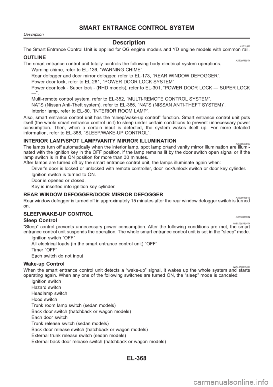
DescriptionNJEL0583The Smart Entrance Control Unit is applied for QG engine models and YD engine models with common rail.
OUTLINENJEL0583S01The smart entrance control unit totally controls the following body electrical system operations.
Warning chime, refer to EL-136, “WARNING CHIME”.
Rear defogger and door mirror defogger, refer to EL-173, “REAR WINDOW DEFOGGER”.
Power door lock, refer to EL-261, “POWER DOOR LOCK SYSTEM”.
Power door lock - Super lock - (RHD models), refer to EL-301, “POWER DOOR LOCK — SUPER LOCK
—”.
Multi-remote control system, refer to EL-352, “MULTI-REMOTE CONTROL SYSTEM”.
NATS (Nissan Anti-Theft system), refer to EL-386, “NATS (NISSAN ANTI-THEFT SYSTEM)”.
Interior lamp, refer to EL-80, “INTERIOR ROOM LAMP”.
Also, smart entrance control unit has the “sleep/wake-up control” function. Smart entrance control unit puts
itself (the whole smart entrance control unit) to sleep under certain conditions to prevent unnecessary power
consumption. Then, when a certain input is detected, the system wakes itself up. For more detailed
information, refer to EL-368, “SLEEP/WAKE-UP CONTROL”.
INTERIOR LAMP/SPOT LAMP/VANITY MIRROR ILLUMINATIONNJEL0583S02The lamps turn off automatically when the interior lamp, spot lamp or/and vanity mirror illumination are illumi-
nated with the ignition key in the OFF position, if the lamp remains lit by the door switch open signal or if the
lamp switch is in the ON position for more than 30 minutes.
After lamps are turned off by the smart entrance control unit, the lamps illuminate again when:
Driver’s door is locked or unlocked with remote controller, door lock/unlock switch or door key cylinder.
Ignition switch is turned to ON.
Door is opened or closed,
Key is inserted into ignition key cylinder.
REAR WINDOW DEFOGGER/DOOR MIRROR DEFOGGERNJEL0583S03Rear window defogger is turned off in approximately 15 minutes after the rear window defogger switch is turned
on.
SLEEP/WAKE-UP CONTROLNJEL0583S04Sleep ControlNJEL0583S0401“Sleep” control prevents unnecessary power consumption. After the following conditions are met, the smart
entrance control unit suspends the operation. The whole smart entrance control unit is set in the “sleep” mode.
Ignition switch “OFF”
All electrical loads (in the smart entrance control unit) “OFF”
Timer “OFF”
Each switch do not input
Wake-up ControlNJEL0583S0402When the smart entrance control unit detects a “wake-up” signal, it wakes up the whole system and starts
operating again. When any one of the following switches are turned ON, the “sleep” mode is canceled:
Ignition switch
Hazard switch
Headlamp switch
Hood switch
Trunk room lamp switch (sedan models)
Back door switch (hatchback or wagon models)
Each door switch
Trunk release switch (sedan models)
Back door release switch (hatchback or wagon models)
External trunk release switch (sedan models)
External back door release switch (hatchback or wagon models)
SMART ENTRANCE CONTROL SYSTEM
Description
EL-368