Knock sensor NISSAN ALMERA N16 2003 Electronic Owner's Guide
[x] Cancel search | Manufacturer: NISSAN, Model Year: 2003, Model line: ALMERA N16, Model: NISSAN ALMERA N16 2003Pages: 3189, PDF Size: 54.76 MB
Page 780 of 3189
![NISSAN ALMERA N16 2003 Electronic Owners Guide EC-450
[QG (WITHOUT EURO-OBD)]
TROUBLE DIAGNOSIS
Air Air duct
55555 5EM-14
Air cleanerEM-14
Air leakage from air duct
(Mass air flow sensor —electric
throttle control actuator)
5555EM-14
Electric t](/img/5/57350/w960_57350-779.png "NISSAN ALMERA N16 2003 Electronic Owners Guide EC-450
[QG (WITHOUT EURO-OBD)]
TROUBLE DIAGNOSIS
Air Air duct
55555 5EM-14
Air cleanerEM-14
Air leakage from air duct
(Mass air flow sensor —electric
throttle control actuator)
5555EM-14
Electric t")
EC-450
[QG (WITHOUT EURO-OBD)]
TROUBLE DIAGNOSIS
Air Air duct
55555 5EM-14
Air cleanerEM-14
Air leakage from air duct
(Mass air flow sensor —electric
throttle control actuator)
5555EM-14
Electric throttle control actuatorEM-16
Air leakage from intake manifold/
Collector/GasketEM-16
Cranking Battery
111111 11SC-3
Alternator circuitSC-27
Starter circuit 3 SC-13
Signal plate/Flywheel/Drive plate 6EM-70
PNP switch
4AT- 11 6,
MT-21
Engine Cylinder head
55555 55 5EM-57
Cylinder head gasket 4 3
Cylinder block
66666 66 64
EM-70
Piston
Piston ring
Connecting rod
Bearing
Crankshaft
Va l v e
mecha-
nismTimin g c hain
55555 55 5EM-47
CamshaftEM-32
Intake valve timing controlEM-47
Intake valve
3EM-57
Exhaust valve
Exhaust Exhaust manifold/Tube/Muffler/
Gasket
55555 55 5EM-19
, FE-
26
Three way catalyst
Lubrica-
tionOil pan/Oil strainer/Oil pump/Oil
filter/Oil gallery
55555 55 52EM-22
, LC-
5, LC-9,
LC-4
Oil level (Low)/Filthy oilLC-8 SYMPTOM
Reference
page
HARD/NO START/RESTART (EXCP. HA)
ENGINE STALL
HESITATION/SURGING/FLAT SPOT
SPARK KNOCK/DETONATION
LACK OF POWER/POOR ACCELERATION
HIGH IDLE/LOW IDLE
ROUGH IDLE/HUNTING
IDLING VIBRATION
SLOW/NO RETURN TO IDLE
OVERHEATS/WATER TEMPERATURE HIGH
EXCESSIVE FUEL CONSUMPTION
EXCESSIVE OIL CONSUMPTION
BATTERY DEAD (UNDER CHARGE)
Warranty symptom code AA AB AC AD AE AF AG AH AJ AK AL AM HA
Page 790 of 3189
![NISSAN ALMERA N16 2003 Electronic Owners Guide EC-460
[QG (WITHOUT EURO-OBD)]
TROUBLE DIAGNOSIS
14 RCamshaft position sensor
(PHASE)[Engine is running]
●Warm-up condition
●Idle speed1.0 - 4.0V
[Engine is running]
●Engine speed is 2,000 rpm.](/img/5/57350/w960_57350-789.png "NISSAN ALMERA N16 2003 Electronic Owners Guide EC-460
[QG (WITHOUT EURO-OBD)]
TROUBLE DIAGNOSIS
14 RCamshaft position sensor
(PHASE)[Engine is running]
●Warm-up condition
●Idle speed1.0 - 4.0V
[Engine is running]
●Engine speed is 2,000 rpm.")
EC-460
[QG (WITHOUT EURO-OBD)]
TROUBLE DIAGNOSIS
14 RCamshaft position sensor
(PHASE)[Engine is running]
●Warm-up condition
●Idle speed1.0 - 4.0V
[Engine is running]
●Engine speed is 2,000 rpm.1.0 - 4.0V
15 W Knock sensor[Engine is running]
●Idle speedApproximately 2.5V
16 W Heated oxygen sensor 2[Engine is running]
●Warm-up condition
●Engine speed is 3,000 rpm quickly after the
following conditions are met.
●Keeping the engine speed between 3,500
and 4,000 rpm for one minute and at idle
for one minute under no load.0 - Approximately 1.0V
19 GY/LEVAP canister purge
volume control solenoid
valve[Engine is running]
●Idle speedBATTERY VOLTAGE
(11 - 14V)
[Engine is running]
●Engine speed is about 2,000 rpm (More
than 100 seconds after starting engine).Approximately 10V TERMI-
NAL
NO.WIRE
COLORITEM CONDITION DATA (DC Voltage)
PBIB0525E
PBIB0526E
PBIB0050E
PBIB0520E
Page 792 of 3189
![NISSAN ALMERA N16 2003 Electronic Owners Guide EC-462
[QG (WITHOUT EURO-OBD)]
TROUBLE DIAGNOSIS
49 W Throttle position sensor 1[Ignition switch “ON”]
●Engine stopped.
●Shift lever position is ″D″ (A/T models).
●Shift lever position i](/img/5/57350/w960_57350-791.png "NISSAN ALMERA N16 2003 Electronic Owners Guide EC-462
[QG (WITHOUT EURO-OBD)]
TROUBLE DIAGNOSIS
49 W Throttle position sensor 1[Ignition switch “ON”]
●Engine stopped.
●Shift lever position is ″D″ (A/T models).
●Shift lever position i")
EC-462
[QG (WITHOUT EURO-OBD)]
TROUBLE DIAGNOSIS
49 W Throttle position sensor 1[Ignition switch “ON”]
●Engine stopped.
●Shift lever position is ″D″ (A/T models).
●Shift lever position is “1st” (M/T models).
●Accelerator pedal fully released.More than 0.36V
[Ignition switch “ON”]
●Engine stopped.
●Shift lever position is ″D″ (A/T models).
●Shift lever position is “1st” (M/T models).
●Accelerator pedal fully depressed.Less than 4.75V
50 Y Mass air flow sensor[Engine is running]
●Warm-up condition
●Idle speed1.0 - 1.7V
[Engine is running]
●Warm-up condition
●Engine speed is 2,500 rpm.1.5 - 2.1V
54 -Sensor ground
(Knock sensor shield circuit)[Engine is running]
●Idle speedApproximately 0V
57 BSensor ground
(Power steering pressure
sensor/Refrigerant pressure
sensor)[Engine is running]
●Warm-up condition
●Idle speedApproximately 0V
60
61
79
80L/R
BR
GY/R
PUIgnition signal No. 3
Ignition signal No. 1
Ignition signal No. 4
Ignition signal No. 2[Engine is running]
●Warm-up condition
●Idle speed0 - 0.1V
[Engine is running]
●Warm-up condition
●Engine speed is 2,000 rpm.0 - 0.2V TERMI-
NAL
NO.WIRE
COLORITEM CONDITION DATA (DC Voltage)
PBIB0521E
PBIB0522E
Page 796 of 3189
![NISSAN ALMERA N16 2003 Electronic Owners Guide EC-466
[QG (WITHOUT EURO-OBD)]
TROUBLE DIAGNOSIS
ENGINE CONTROL COMPONENT PARTS/CONTROL SYSTEMS APPLICATION
X: Applicable
*1: This item includes 1st trip DTCs.
*2: This mode includes 1st trip freeze f](/img/5/57350/w960_57350-795.png "NISSAN ALMERA N16 2003 Electronic Owners Guide EC-466
[QG (WITHOUT EURO-OBD)]
TROUBLE DIAGNOSIS
ENGINE CONTROL COMPONENT PARTS/CONTROL SYSTEMS APPLICATION
X: Applicable
*1: This item includes 1st trip DTCs.
*2: This mode includes 1st trip freeze f")
EC-466
[QG (WITHOUT EURO-OBD)]
TROUBLE DIAGNOSIS
ENGINE CONTROL COMPONENT PARTS/CONTROL SYSTEMS APPLICATION
X: Applicable
*1: This item includes 1st trip DTCs.
*2: This mode includes 1st trip freeze frame data or freeze frame data. The items appear on CONSULT-II screen in freeze frame data
mode only if a 1st trip DTC or DTC is detected. For details, refer to EC-468
.
CONSULT-II INSPECTION PROCEDURE
1. Turn ignition switch OFF.
ItemDIAGNOSTIC TEST MODE
WORK
SUPPORTSELF-DIAGNOSTIC
RESULTS
DATA
MONI-
TORDATA
MONI-
TOR
(SPEC)ACTIVE
TEST DTC*1FREEZE
FRAME
DATA
*2
ENGINE CONTROL COMPONENT PARTS
INPUT
Crankshaft position sensor (POS)××××
Camshaft position sensor (PHASE)×××
Mass air flow sensor×××
Engine coolant temperature sensor×××××
Heated oxygen sensor 1×××
Heated oxygen sensor 2×××
Vehicle speed signal×××
Accelerator pedal position sensor×××
Throttle position sensor×××
Intake air temperature sensor××
Knock sensor×
Refrigerant pressure sensor××
Closed throttle position switch (accelerator
pedal position sensor signal)××
Air conditioner switch××
Park/neutral position (PNP) switch××
Stop lamp switch×××
Power steering pressure sensor××
Battery voltage××
Electrical load signal××
ENGINE CONTROL COMPONENT PARTS
OUTPUT
Injectors×× ×
Power transistor (Ignition timing)×× ×
Throttle control motor relay×××
Throttle control motor×
EVAP canister purge volume control sole-
noid valve×× ×
Air conditioner relay××
Fuel pump relay××××
Cooling fan relay××××
Heated oxygen sensor 1 heater××
Heated oxygen sensor 2 heater××
Intake valve timing control solenoid valve×× ×
Calculated load value×××
Page 880 of 3189
![NISSAN ALMERA N16 2003 Electronic Owners Guide EC-550
[QG (WITHOUT EURO-OBD)]
DTC P0327, P0328 KS
DTC P0327, P0328 KS
PFP:22060
Component DescriptionEBS00KHG
The knock sensor is attached to the cylinder block. It senses engine
knocking using a](/img/5/57350/w960_57350-879.png "NISSAN ALMERA N16 2003 Electronic Owners Guide EC-550
[QG (WITHOUT EURO-OBD)]
DTC P0327, P0328 KS
DTC P0327, P0328 KS
PFP:22060
Component DescriptionEBS00KHG
The knock sensor is attached to the cylinder block. It senses engine
knocking using a")
EC-550
[QG (WITHOUT EURO-OBD)]
DTC P0327, P0328 KS
DTC P0327, P0328 KS
PFP:22060
Component DescriptionEBS00KHG
The knock sensor is attached to the cylinder block. It senses engine
knocking using a piezoelectric element. A knocking vibration from
the cylinder block is sensed as vibrational pressure. This pressure is
converted into a voltage signal and sent to the ECM.
On Board Diagnosis LogicEBS00KHH
The MI will not light up for this diagnosis.
DTC Confirmation ProcedureEBS00KHI
NOTE:
If “DTC Confirmation Procedure” has been previously conducted, always turn ignition switch “OFF” and wait at
least 10 seconds before conducting the next test.
TESTING CONDITION:
Before performing the following procedure, confirm that battery voltage is more than 10V at idle.
WITH CONSULT-II
1. Turn ignition switch “ON” and select “DATA MONITOR” mode with CONSULT-II.
2. Start engine and run it for at least 5 seconds at idle speed.
3. If 1st trip DTC is detected, go to EC-552, "
Diagnostic Procedure"
.
WITHOUT CONSULT-II
1. Start engine and run it for at least 5 seconds at idle speed.
2. Turn ignition switch “OFF”, wait at least 10 seconds and then turn “ON”.
3. Perform “Diagnostic Test Mode II (Self-diagnostic results)” with ECM.
4. If 1st trip DTC is detected, go to EC-552, "
Diagnostic Procedure" .
MBIB0102E
DTC No. Trouble Diagnosis Name DTC Detected Condition Possible Cause
P0327
0327Knock sensor circuit low
inputAn excessively low voltage from the sensor is
sent to ECM.
●Harness or connectors
(The sensor circuit is open or shorted.)
●Knock sensor P0328
0328Knock sensor circuit high
inputAn excessively high voltage from the sensor is
sent to ECM.
SEF058Y
Page 882 of 3189
![NISSAN ALMERA N16 2003 Electronic Owners Guide EC-552
[QG (WITHOUT EURO-OBD)]
DTC P0327, P0328 KS
Specification data are reference values and are measured between each terminal and ground.
CAUTION:
Do not use ECM ground terminals when measuring in](/img/5/57350/w960_57350-881.png "NISSAN ALMERA N16 2003 Electronic Owners Guide EC-552
[QG (WITHOUT EURO-OBD)]
DTC P0327, P0328 KS
Specification data are reference values and are measured between each terminal and ground.
CAUTION:
Do not use ECM ground terminals when measuring in")
EC-552
[QG (WITHOUT EURO-OBD)]
DTC P0327, P0328 KS
Specification data are reference values and are measured between each terminal and ground.
CAUTION:
Do not use ECM ground terminals when measuring input/output voltage. Doing so may result in dam-
age to the ECM's transistor. Use a ground other than ECM terminals, such as the ground.
Diagnostic ProcedureEBS00KHK
1. CHECK KNOCK SENSOR INPUT SIGNAL CIRCUIT-I
1. Turn ignition switch “OFF”.
2. Disconnect ECM harness connector.
3. Check resistance between ECM terminal 15 and engine ground. Refer to Wiring Diagram.
NOTE:
It is necessary to use an ohmmeter which can measure more than 10 MΩ.
4. Also check harness for short to ground and short to power.
OK or NG
OK >> GO TO 4.
NG >> GO TO 2.
2. CHECK KNOCK SENSOR INPUT SIGNAL CIRCUIT-II
1. Disconnect knock sensor harness connector.
2. Check harness continuity between ECM terminal 15 and knock
sensor terminal 1.
Refer to Wiring Diagram.
3. Also check harness for short to ground and short to power.
OK or NG
OK >> GO TO 3.
NG >> Repair open circuit or short to ground or short to power
in harness or connectors.
3. CHECK KNOCK SENSOR
Refer to EC-553, "
Component Inspection" .
OK or NG
OK >> GO TO 5.
NG >> Replace knock sensor.
TERMI-
NAL
NO.WIRE
COLORITEM CONDITION DATA (DC Voltage)
15 W Knock sensor[Engine is running]
●Idle speedApproximately 2.5V
54 —Knock sensor shield circuit
ground[Engine is running]
●Idle speedApproximately 0V
Resistance: Approximately 530 - 590kΩ [at 20°C (68°F)]
Continuity should exist.
MBIB0102E
Page 883 of 3189
![NISSAN ALMERA N16 2003 Electronic Owners Guide DTC P0327, P0328 KS
EC-553
[QG (WITHOUT EURO-OBD)]
C
D
E
F
G
H
I
J
K
L
MA
EC
4.RETIGHTEN GROUND SCREWS
Loosen and retighten engine ground screws.
>> GO TO 5.
5.CHECK INTERMITTENT INCIDENT
Refer to EC-](/img/5/57350/w960_57350-882.png "NISSAN ALMERA N16 2003 Electronic Owners Guide DTC P0327, P0328 KS
EC-553
[QG (WITHOUT EURO-OBD)]
C
D
E
F
G
H
I
J
K
L
MA
EC
4.RETIGHTEN GROUND SCREWS
Loosen and retighten engine ground screws.
>> GO TO 5.
5.CHECK INTERMITTENT INCIDENT
Refer to EC-")
DTC P0327, P0328 KS
EC-553
[QG (WITHOUT EURO-OBD)]
C
D
E
F
G
H
I
J
K
L
MA
EC
4.RETIGHTEN GROUND SCREWS
Loosen and retighten engine ground screws.
>> GO TO 5.
5.CHECK INTERMITTENT INCIDENT
Refer to EC-485, "
TROUBLE DIAGNOSIS FOR INTERMITTENT INCIDENT" .
>>INSPECTION END
Component InspectionEBS00KHL
KNOCK SENSOR
Check resistance between knock sensor terminal 1 and ground.
NOTE:
It is necessary to use an ohmmeter which can measure more
than 10 MΩ.
CAUTION:
Do not use any knock sensors that have been dropped or phys-
ically damaged. Use only new ones.
Removal and InstallationEBS00KHM
KNOCK SENSOR
Refer to EM-70, "CYLINDER BLOCK" .
MBIB0095E
Resistance: Approximately 530 - 590kΩ [at 20°C (68°F)]
SEF227W
Page 1109 of 3189
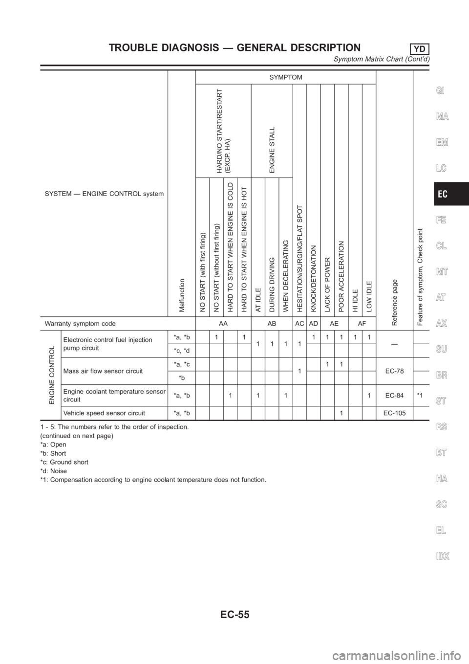
SYSTEM — ENGINE CONTROL system
Malfunction
SYMPTOM
Reference page
Feature of symptom, Check pointHARD/NO START/RESTART
(EXCP. HA)
ENGINE STALL
HESITATION/SURGING/FLAT SPOT
KNOCK/DETONATION
LACK OF POWER
POOR ACCELERATION
HI IDLE
LOW IDLE NO START (with first firing)
NO START (without first firing)
HARD TO START WHEN ENGINE IS COLD
HARD TO START WHEN ENGINE IS HOT
AT IDLE
DURING DRIVING
WHEN DECELERATINGWarranty symptom code AA AB AC AD AE AF
ENGINE CONTROL
Electronic control fuel injection
pump circuit*a, *b 1 1
111111111
—
*c, *d
Mass air flow sensor circuit*a, *c
111
EC-78
*b
Engine coolant temperature sensor
circuit*a, *b 1 1 1 1 EC-84 *1
Vehicle speed sensor circuit *a, *b 1 EC-105
1 - 5: The numbers refer to the order of inspection.
(continued on next page)
*a: Open
*b: Short
*c: Ground short
*d: Noise
*1: Compensation according to engine coolant temperature does not function.
GI
MA
EM
LC
FE
CL
MT
AT
AX
SU
BR
ST
RS
BT
HA
SC
EL
IDX
TROUBLE DIAGNOSIS — GENERAL DESCRIPTIONYD
Symptom Matrix Chart (Cont’d)
EC-55
Page 1111 of 3189
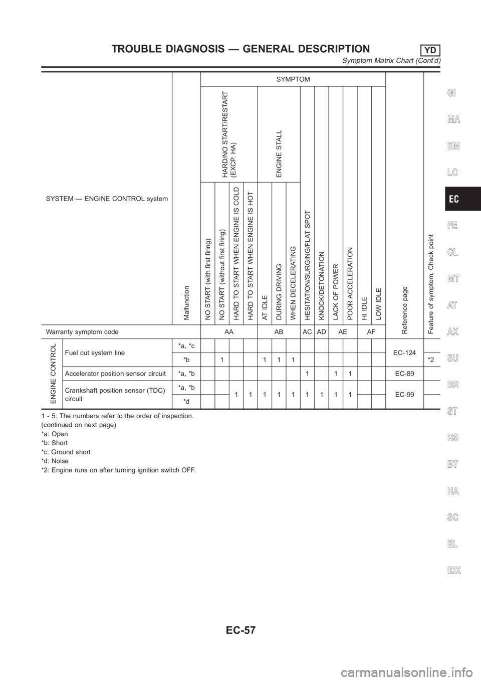
SYSTEM — ENGINE CONTROL system
Malfunction
SYMPTOM
Reference page
Feature of symptom, Check pointHARD/NO START/RESTART
(EXCP. HA)
ENGINE STALL
HESITATION/SURGING/FLAT SPOT
KNOCK/DETONATION
LACK OF POWER
POOR ACCELERATION
HI IDLE
LOW IDLE NO START (with first firing)
NO START (without first firing)
HARD TO START WHEN ENGINE IS COLD
HARD TO START WHEN ENGINE IS HOT
AT IDLE
DURING DRIVING
WHEN DECELERATINGWarranty symptom code AA AB AC AD AE AF
ENGINE CONTROL
Fuel cut system line*a, *c
EC-124
*b 1 1 1 1 *2
Accelerator position sensor circuit *a, *b 1 1 1 EC-89
Crankshaft position sensor (TDC)
circuit*a, *b
111111111 EC-99
*d
1 - 5: The numbers refer to the order of inspection.
(continued on next page)
*a: Open
*b: Short
*c: Ground short
*d: Noise
*2: Engine runs on after turning ignition switch OFF.
GI
MA
EM
LC
FE
CL
MT
AT
AX
SU
BR
ST
RS
BT
HA
SC
EL
IDX
TROUBLE DIAGNOSIS — GENERAL DESCRIPTIONYD
Symptom Matrix Chart (Cont’d)
EC-57
Page 1113 of 3189
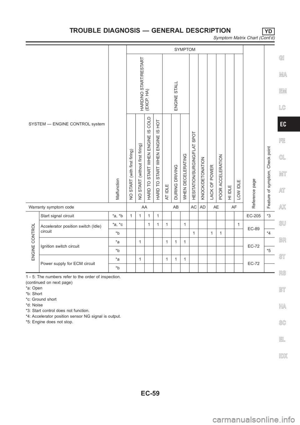
SYSTEM — ENGINE CONTROL system
Malfunction
SYMPTOM
Reference page
Feature of symptom, Check pointHARD/NO START/RESTART
(EXCP. HA)
ENGINE STALL
HESITATION/SURGING/FLAT SPOT
KNOCK/DETONATION
LACK OF POWER
POOR ACCELERATION
HI IDLE
LOW IDLE NO START (with first firing)
NO START (without first firing)
HARD TO START WHEN ENGINE IS COLD
HARD TO START WHEN ENGINE IS HOT
AT IDLE
DURING DRIVING
WHEN DECELERATINGWarranty symptom code AA AB AC AD AE AF
ENGINE CONTROL
Start signal circuit *a, *b1111 EC-205*3
Accelerator position switch (Idle)
circuit*a, *c 1 1 1 1 1
EC-89
*b 1 1 1 *4
Ignition switch circuit*a 1 111
EC-72
*b*5
Power supply for ECM circuit*a 1 111
EC-72
*b
1 - 5: The numbers refer to the order of inspection.
(continued on next page)
*a: Open
*b: Short
*c: Ground short
*d: Noise
*3: Start control does not function.
*4: Accelerator position sensor NG signal is output.
*5: Engine does not stop.
GI
MA
EM
LC
FE
CL
MT
AT
AX
SU
BR
ST
RS
BT
HA
SC
EL
IDX
TROUBLE DIAGNOSIS — GENERAL DESCRIPTIONYD
Symptom Matrix Chart (Cont’d)
EC-59