oil temperature NISSAN ALMERA N16 2003 Electronic Repair Manual
[x] Cancel search | Manufacturer: NISSAN, Model Year: 2003, Model line: ALMERA N16, Model: NISSAN ALMERA N16 2003Pages: 3189, PDF Size: 54.76 MB
Page 10 of 3189
Do not use gasoline, kerosine, diesel fuel, gas oil, thinners or
solvents for cleaning skin.
If skin disorders develop, obtain medical advice without delay.
Where practicable, degrease components prior to handling.
Where there is a risk of eye contact, eye protection should be
worn, for example, chemical goggles or face shields; in addi-
tion an eye wash facility should be provided.
Environmental Protection PrecautionsNJGI0001S0702Burning used engine oil in small space heaters or boilers can be
recommended only for units of approved design. The heating sys-
tem must meet the requirements of HM Inspectorate of Pollution for
small burners of less than 0.4 MW. If in doubt, check with the
appropriate local authority and/or manufacturer of the approved
appliance.
Dispose of used oil and used oil filters through authorized waste
disposal contractors to licensed waste disposal sites, or to the
waste oil reclamation trade. If in doubt, contact the local authority
for advice on disposal facilities.
It is illegal to pour used oil on to the ground, down sewers or drains,
or into water courses.
The regulations concerning the pollution vary between
regions.
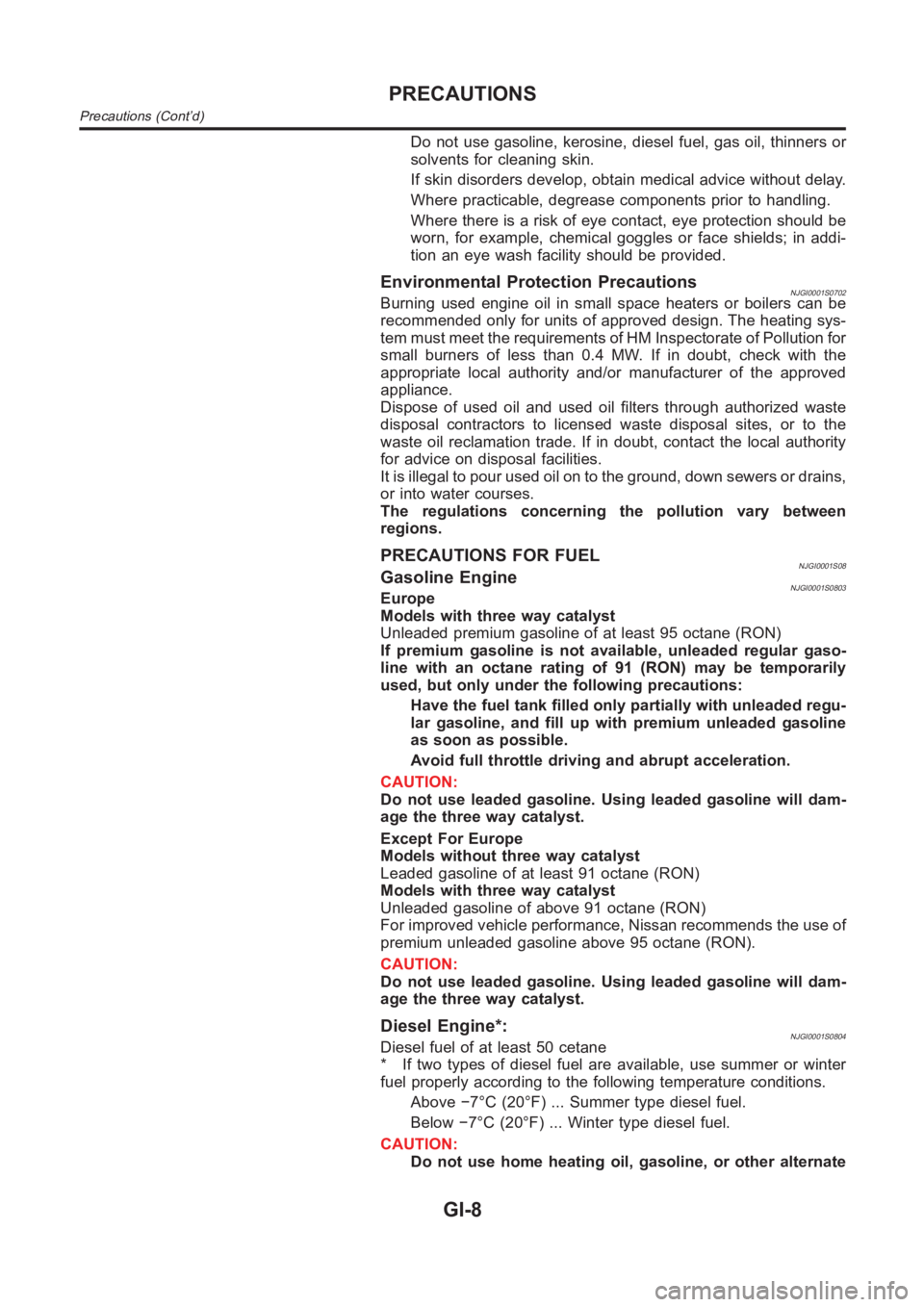
PRECAUTIONS FOR FUELNJGI0001S08Gasoline EngineNJGI0001S0803Europe
Models with three way catalyst
Unleaded premium gasoline of at least 95 octane (RON)
If premium gasoline is not available, unleaded regular gaso-
line with an octane rating of 91 (RON) may be temporarily
used, but only under the following precautions:
Have the fuel tank filled only partially with unleaded regu-
lar gasoline, and fill up with premium unleaded gasoline
as soon as possible.
Avoid full throttle driving and abrupt acceleration.
CAUTION:
Do not use leaded gasoline. Using leaded gasoline will dam-
age the three way catalyst.
Except For Europe
Models without three way catalyst
Leaded gasoline of at least 91 octane (RON)
Models with three way catalyst
Unleaded gasoline of above 91 octane (RON)
For improved vehicle performance, Nissan recommends the use of
premium unleaded gasoline above 95 octane (RON).
CAUTION:
Do not use leaded gasoline. Using leaded gasoline will dam-
age the three way catalyst.
Diesel Engine*:NJGI0001S0804Diesel fuel of at least 50 cetane
* If two types of diesel fuel are available, use summer or winter
fuel properly according to the following temperature conditions.
Above −7°C (20°F) ... Summer type diesel fuel.
Below −7°C (20°F) ... Winter type diesel fuel.
CAUTION:
Do not use home heating oil, gasoline, or other alternate
PRECAUTIONS
Precautions (Cont’d)
GI-8
Page 62 of 3189
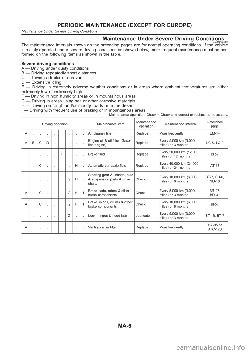
Maintenance Under Severe Driving Conditions=NJMA0005S06The maintenance intervals shown on the preceding pages are for normal operating conditions. If the vehicle
is mainly operated under severe driving conditions as shown below, more frequent maintenance must be per-
formed on the following items as shown in the table.
Severe driving conditions
A — Driving under dusty conditions
B — Driving repeatedly short distances
C — Towing a trailer or caravan
D — Extensive idling
E — Driving in extremely adverse weather conditions or in areas where ambient temperatures are either
extremely low or extremely high
F — Driving in high humidity areas or in mountainous areas
G — Driving in areas using salt or other corrosive materials
H — Driving on rough and/or muddy roads or in the desert
I — Driving with frequent use of braking or in mountainous areas
Maintenance operation: Check = Check and correct or replace as necessary.
Driving condition Maintenance itemMaintenance
operationMaintenance intervalReference
page
A........Aircleaner filter Replace More frequently EM-14
ABCD.....Engine oil & oil filter (Gaso-
line engine)ReplaceEvery 5,000 km (3,000
miles) or 3 monthsLC-8, LC-9
.....F...Brakefluid ReplaceEvery 20,000 km (12,000
miles) or 12 monthsBR-7
..C....H.Automatictransaxlefluid ReplaceEvery 40,000 km (24,000
miles) or 24 monthsAT-13
......GH.Steering gear & linkage, axle
& suspension parts & drive
shaftsCheckEvery 10,000 km (6,000
miles) or 6 monthsST-7, SU-6,
SU-18
A.C...GHIBrake pads, rotors & other
brake componentsCheckEvery 5,000 km (3,000
miles) or 3 monthsBR-27,
BR-31
A.C...GHIBrake linings, drums & other
brake componentsCheckEvery 10,000 km (6,000
miles) or 6 monthsBR-7
......G..Lock,hinges & hood latch LubricateEvery 5,000 km (3,000
miles) or 3 monthsBT-16, BT-7
A........Ventilation air filter Replace More frequentlyHA-95 or
ATC-128
PERIODIC MAINTENANCE (EXCEPT FOR EUROPE)
Maintenance Under Severe Driving Conditions
MA-6
Page 67 of 3189
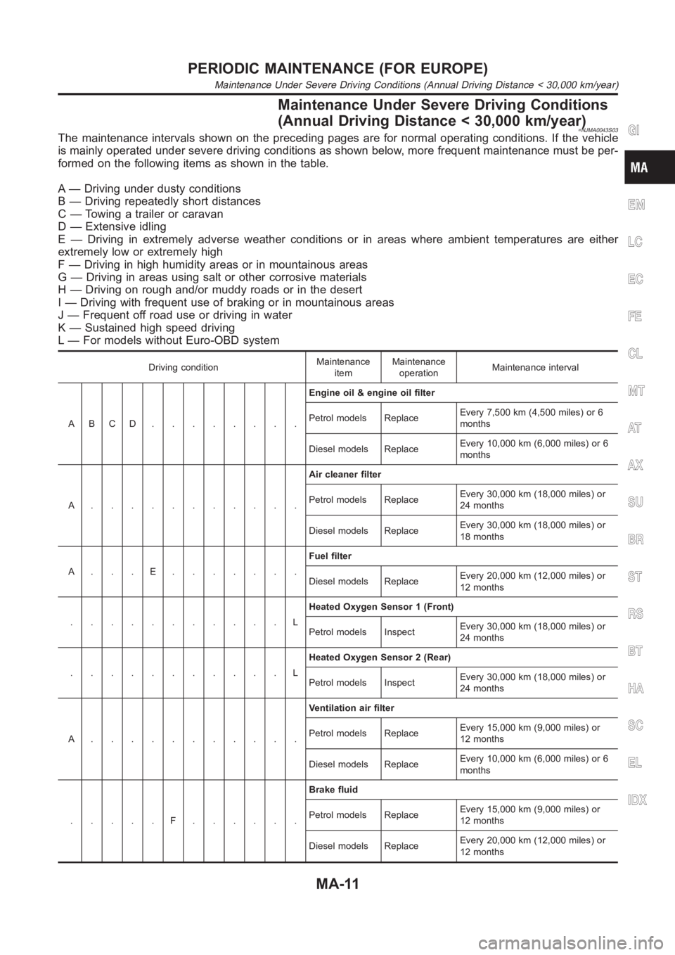
Maintenance Under Severe Driving Conditions
(Annual Driving Distance < 30,000 km/year)
=NJMA0043S03The maintenance intervals shown on the preceding pages are for normal operating conditions. If the vehicle
is mainly operated under severe driving conditions as shown below, more frequent maintenance must be per-
formed on the following items as shown in the table.
A — Driving under dusty conditions
B — Driving repeatedly short distances
C — Towing a trailer or caravan
D — Extensive idling
E — Driving in extremely adverse weather conditions or in areas where ambient temperatures are either
extremely low or extremely high
F — Driving in high humidity areas or in mountainous areas
G — Driving in areas using salt or other corrosive materials
H — Driving on rough and/or muddy roads or in the desert
I — Driving with frequent use of braking or in mountainous areas
J — Frequent off road use or driving in water
K — Sustained high speed driving
L — For models without Euro-OBD system
Driving conditionMaintenance
itemMaintenance
operationMaintenance interval
ABCD........Engine oil & engine oil filter
Petrol models ReplaceEvery 7,500 km (4,500 miles) or 6
months
Diesel models ReplaceEvery 10,000 km (6,000 miles) or 6
months
A...........Air cleaner filter
Petrol models ReplaceEvery 30,000 km (18,000 miles) or
24 months
Diesel models ReplaceEvery 30,000 km (18,000 miles) or
18 months
A...E.......Fuel filter
Diesel models ReplaceEvery 20,000 km (12,000 miles) or
12 months
...........LHeated Oxygen Sensor 1 (Front)
Petrol models InspectEvery 30,000 km (18,000 miles) or
24 months
...........LHeated Oxygen Sensor 2 (Rear)
Petrol models InspectEvery 30,000 km (18,000 miles) or
24 months
A...........Ventilation air filter
Petrol models ReplaceEvery 15,000 km (9,000 miles) or
12 months
Diesel models ReplaceEvery 10,000 km (6,000 miles) or 6
months
.....F......Brake fluid
Petrol models ReplaceEvery 15,000 km (9,000 miles) or
12 months
Diesel models ReplaceEvery 20,000 km (12,000 miles) or
12 months
GI
EM
LC
EC
FE
CL
MT
AT
AX
SU
BR
ST
RS
BT
HA
SC
EL
IDX
PERIODIC MAINTENANCE (FOR EUROPE)
Maintenance Under Severe Driving Conditions (Annual Driving Distance < 30,000 km/year)
MA-11
Page 73 of 3189
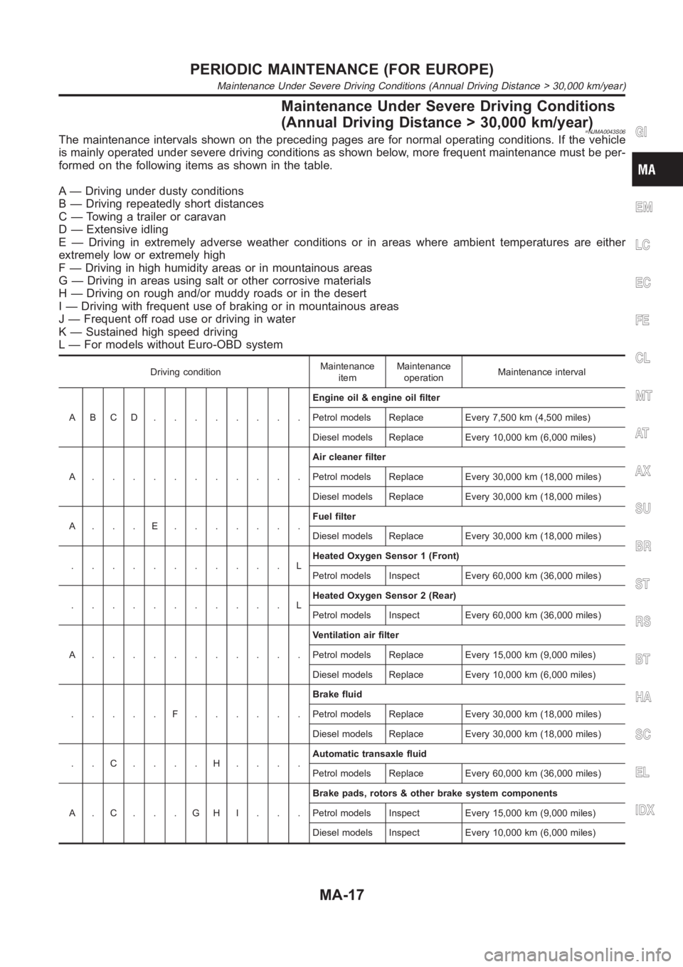
Maintenance Under Severe Driving Conditions
(Annual Driving Distance > 30,000 km/year)
=NJMA0043S06The maintenance intervals shown on the preceding pages are for normal operating conditions. If the vehicle
is mainly operated under severe driving conditions as shown below, more frequent maintenance must be per-
formed on the following items as shown in the table.
A — Driving under dusty conditions
B — Driving repeatedly short distances
C — Towing a trailer or caravan
D — Extensive idling
E — Driving in extremely adverse weather conditions or in areas where ambient temperatures are either
extremely low or extremely high
F — Driving in high humidity areas or in mountainous areas
G — Driving in areas using salt or other corrosive materials
H — Driving on rough and/or muddy roads or in the desert
I — Driving with frequent use of braking or in mountainous areas
J — Frequent off road use or driving in water
K — Sustained high speed driving
L — For models without Euro-OBD system
Driving conditionMaintenance
itemMaintenance
operationMaintenance interval
ABCD........Engine oil & engine oil filter
Petrol models Replace Every 7,500 km (4,500 miles)
Diesel models Replace Every 10,000 km (6,000 miles)
A...........Air cleaner filter
Petrol models Replace Every 30,000 km (18,000 miles)
Diesel models Replace Every 30,000 km (18,000 miles)
A...E.......Fuel filter
Diesel models Replace Every 30,000 km (18,000 miles)
...........LHeated Oxygen Sensor 1 (Front)
Petrol models Inspect Every 60,000 km (36,000 miles)
...........LHeated Oxygen Sensor 2 (Rear)
Petrol models Inspect Every 60,000 km (36,000 miles)
A...........Ventilation air filter
Petrol models Replace Every 15,000 km (9,000 miles)
Diesel models Replace Every 10,000 km (6,000 miles)
.....F......Brake fluid
Petrol models Replace Every 30,000 km (18,000 miles)
Diesel models Replace Every 30,000 km (18,000 miles)
..C....H....Automatic transaxle fluid
Petrol models Replace Every 60,000 km (36,000 miles)
A.C...GHI...Brake pads, rotors & other brake system components
Petrol models Inspect Every 15,000 km (9,000 miles)
Diesel models Inspect Every 10,000 km (6,000 miles)
GI
EM
LC
EC
FE
CL
MT
AT
AX
SU
BR
ST
RS
BT
HA
SC
EL
IDX
PERIODIC MAINTENANCE (FOR EUROPE)
Maintenance Under Severe Driving Conditions (Annual Driving Distance > 30,000 km/year)
MA-17
Page 138 of 3189
![NISSAN ALMERA N16 2003 Electronic Repair Manual EM-60
[QG]
CYLINDER HEAD
3. Tighten cylinder auxiliary bolts (11) to (14) in numerical order
shown in figure.
●Pay attention to shank length under bolt head. [11: 20 mm
(0.79 in), 12 - 14: NISSAN ALMERA N16 2003 Electronic Repair Manual EM-60
[QG]
CYLINDER HEAD
3. Tighten cylinder auxiliary bolts (11) to (14) in numerical order
shown in figure.
●Pay attention to shank length under bolt head. [11: 20 mm
(0.79 in), 12 - 14:](/img/5/57350/w960_57350-137.png)
EM-60
[QG]
CYLINDER HEAD
3. Tighten cylinder auxiliary bolts (11) to (14) in numerical order
shown in figure.
●Pay attention to shank length under bolt head. [11: 20 mm
(0.79 in), 12 - 14: 25 mm (0.98 in)]
Disassembly and AssemblyEBS00LQJ
CAUTION:
●When installing camshafts, chain tensioners, oil seals or other sliding parts, lubricate contacting
surface with new engine oil.
●Apply new engine oil to threads and seat surface when installing cylinder head, camshaft
sprocket, crankshaft pulley and camshaft bracket.
●Attach tags to valve lifters so as not to mix them up.
DISASSEMBLY
1. Remove adjusting shim (if so equipped) and valve lifter.
●Confirm installation point.
SEM900F
PBIC0973E
1. Cylinder head 2. Valve (INT) 3. Valve (EXH)
4. Valve seat 5. Engine coolant temperature sensor 6. Copper washer
7. Spark plug tube 8. Spark plug
Page 139 of 3189
![NISSAN ALMERA N16 2003 Electronic Repair Manual CYLINDER HEAD
EM-61
[QG]
C
D
E
F
G
H
I
J
K
L
MA
EM
2. Remove valve collet.
●Compress valve spring with valve spring compressor (special
service tool). Remove valve collet with magnet driver.
3. Remo NISSAN ALMERA N16 2003 Electronic Repair Manual CYLINDER HEAD
EM-61
[QG]
C
D
E
F
G
H
I
J
K
L
MA
EM
2. Remove valve collet.
●Compress valve spring with valve spring compressor (special
service tool). Remove valve collet with magnet driver.
3. Remo](/img/5/57350/w960_57350-138.png)
CYLINDER HEAD
EM-61
[QG]
C
D
E
F
G
H
I
J
K
L
MA
EM
2. Remove valve collet.
●Compress valve spring with valve spring compressor (special
service tool). Remove valve collet with magnet driver.
3. Remove valve spring retainer and valve spring.
4. Push valve stem to combustion chamber side, and remove
valve.
●Inspect valve guide clearance before removal. Refer to EM-
63, "VALVE GUIDE CLEARANCE" .
●Confirm installation point.
5. Remove valve oil seal with valve oil seal puller (special service
tool).
6. Remove valve spring seat.
7. When valve seat must be replaced, refer to EM-64, "
VA LV E
SEAT REPLACEMENT" .
8. When valve guide must be replaced, refer to EM-63, "
VA LV E
GUIDE REPLACEMENT" .
9. Remove spark plug with spark plug wrench (commercial service
tool).
10. Remove engine coolant temperature sensor.
CAUTION:
Do not shock it.
11. Remove spark plug tube, as necessary.
●Using a pair of pliers, pull spark plug tube out of cylinder head.
CAUTION:
●Take care not to damage cylinder head.
●Once removed, a spark plug tube will be deformed and cannot be reused. Do not remove it
unless absolutely necessary.
ASSEMBLY
1. Install valve guide. Refer to EM-63, "VALVE GUIDE REPLACEMENT" .
2. Install valve seat. Refer to EM-64, "
VALVE SEAT REPLACEMENT" .
3. Install valve oil seal.
●Install with valve oil seal drift (special service tool) to match
dimension in illustration.
4. Install valve spring seat.
5. Install valve.
●Install larger diameter to intake side.
6. Install valve spring.
7. Install valve spring retainer.
PBIC1015E
SEM909F
PBIC0576E
Page 140 of 3189
![NISSAN ALMERA N16 2003 Electronic Repair Manual EM-62
[QG]
CYLINDER HEAD
8. Install valve collet.
●Compress valve spring with valve spring compressor (special
service tool). Install valve collet with magnet hand.
●Tap stem edge lightly with pla NISSAN ALMERA N16 2003 Electronic Repair Manual EM-62
[QG]
CYLINDER HEAD
8. Install valve collet.
●Compress valve spring with valve spring compressor (special
service tool). Install valve collet with magnet hand.
●Tap stem edge lightly with pla](/img/5/57350/w960_57350-139.png)
EM-62
[QG]
CYLINDER HEAD
8. Install valve collet.
●Compress valve spring with valve spring compressor (special
service tool). Install valve collet with magnet hand.
●Tap stem edge lightly with plastic hammer after installation to
check its installed condition.
9. Install adjusting shim (if so equipped) and valve lifter.
10. Install engine coolant temperature sensor.
●Apply Genuine Liquid Gasket or equivalent to the thread.
11. Install spark plug tube.
●Press-fit spark plug tube following procedure below.
a. Remove old liquid gasket adhering to cylinder-head mounting
hole.
b. Apply liquid gasket to area within approximately 15 mm (0.59 in)
from edge of spark plug tube press-fit side.
●Use Genuine Liquid Gasket or equivalent.
c. Using a drift, press-fit spark plug tube so that its height “H” is as
specified in the figure.
CAUTION:
●When press-fitting, take care not to deform spark plug tube.
●After press-fitting, wipe off liquid gasket protruding onto cylinder-head upper face.
12. Install spark plug with spark plug wrench (commercial service tool).
Inspection After DisassemblyEBS00LQK
CYLINDER HEAD DISTORTION
1. Wipe off oil and remove water scale (like deposit), gasket,
sealer, carbon, etc with scraper.
CAUTION:
Use utmost care not to allow gasket debris to enter pas-
sages for oil or water.
2. At each of several locations on bottom surface of cylinder head,
measure distortion in six directions.
VALVE DIMENSIONS
Check dimensions of each valve. For dimensions, refer to EM-94,
"VA LV E" .
PBIC1016E
Standard press-fit height “H” :
: 41.0 - 42.0 mm (1.61 - 1.65 in)KBIA1248E
Limit : 0.1 mm (0.004 in)
PBIC0075E
SEM188A
Page 278 of 3189
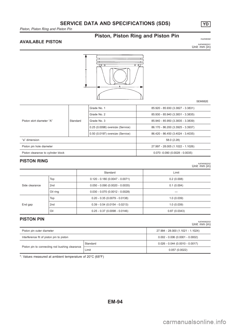
Piston, Piston Ring and Piston Pin=NJEM0082AVAILABLE PISTONNJEM0082S01Unit: mm (in)
SEM882E
Piston skirt diameter “A” StandardGrade No. 1 85.920 - 85.930 (3.3827 - 3.3831)
Grade No. 2 85.930 - 85.940 (3.3831 - 3.3835)
Grade No. 3 85.940 - 85.950 (3.3835 - 3.3839)
0.25 (0.0098) oversize (Service) 86.170 - 86.200 (3.3925 - 3.3937)
0.50 (0.0197) oversize (Service) 86.420 - 86.450 (3.4024 - 3.4035)
“a” dimension58.0 (2.28)
Piston pin hole diameter27.997 - 28.005 (1.1022 - 1.1026)
Piston clearance to cylinder block 0.070 -0.090 (0.0028 - 0.0035)
PISTON RINGNJEM0082S02Unit: mm (in)
Standard Limit
Side clearanceTop 0.120 - 0.180 (0.0047 - 0.0071) 0.2 (0.008)
2nd 0.050 - 0.090 (0.0020 - 0.0035) 0.1 (0.004)
Oil ring 0.030 - 0.070 (0.0012 - 0.0028) —
End gapTop 0.20 - 0.35 (0.0079 - 0.0138) 1.0 (0.039)
2nd 0.39 - 0.54 (0.0154 - 0.0213) 1.0 (0.039)
Oil 0.25 - 0.37 (0.0098 - 0.0146) 0.87 (0.0343)
PISTON PINNJEM0082S03Unit: mm (in)
Piston pin outer diameter27.994 - 28.000 (1.1021 - 1.1024)
Interference fit of piston pin to piston 0.002 - 0.006 (0.0001 - 0.0002)
Piston pin to connecting rod bushing clearanceStandard 0.026 - 0.044 (0.0010 - 0.0017)
Limit 0.057 (0.0022)
*: Values measured at ambient temperature of 20°C (68°F)
SERVICE DATA AND SPECIFICATIONS (SDS)YD
Piston, Piston Ring and Piston Pin
EM-94
Page 287 of 3189
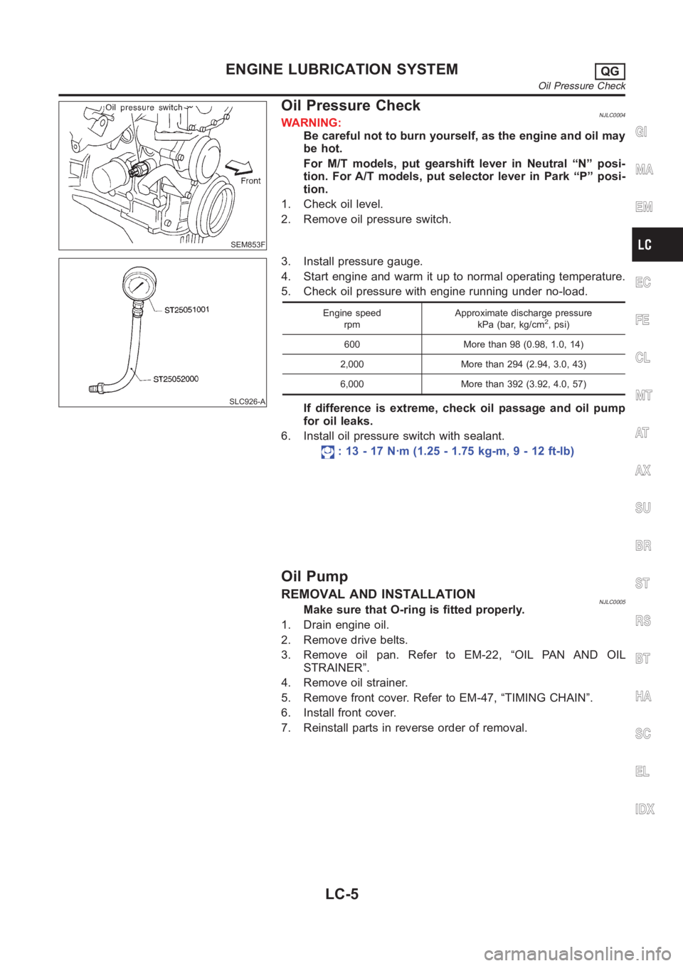
SEM853F
Oil Pressure CheckNJLC0004WARNING:
Be careful not to burn yourself, as the engine and oil may
be hot.
For M/T models, put gearshift lever in Neutral “N” posi-
tion. For A/T models, put selector lever in Park “P” posi-
tion.
1. Check oil level.
2. Remove oil pressure switch.
SLC926-A
3. Install pressure gauge.
4. Start engine and warm it up to normal operating temperature.
5. Check oil pressure with engine running under no-load.
Engine speed
rpmApproximate discharge pressure
kPa (bar, kg/cm2, psi)
600 More than 98 (0.98, 1.0, 14)
2,000 More than 294 (2.94, 3.0, 43)
6,000 More than 392 (3.92, 4.0, 57)
If difference is extreme, check oil passage and oil pump
for oil leaks.
6. Install oil pressure switch with sealant.
: 13 - 17 N·m (1.25 - 1.75 kg-m, 9 - 12 ft-lb)
Oil Pump
REMOVAL AND INSTALLATIONNJLC0005Make sure that O-ring is fitted properly.
1. Drain engine oil.
2. Remove drive belts.
3. Remove oil pan. Refer to EM-22, “OIL PAN AND OIL
STRAINER”.
4. Remove oil strainer.
5. Remove front cover. Refer to EM-47, “TIMING CHAIN”.
6. Install front cover.
7. Reinstall parts in reverse order of removal.
GI
MA
EM
EC
FE
CL
MT
AT
AX
SU
BR
ST
RS
BT
HA
SC
EL
IDX
ENGINE LUBRICATION SYSTEMQG
Oil Pressure Check
LC-5
Page 298 of 3189
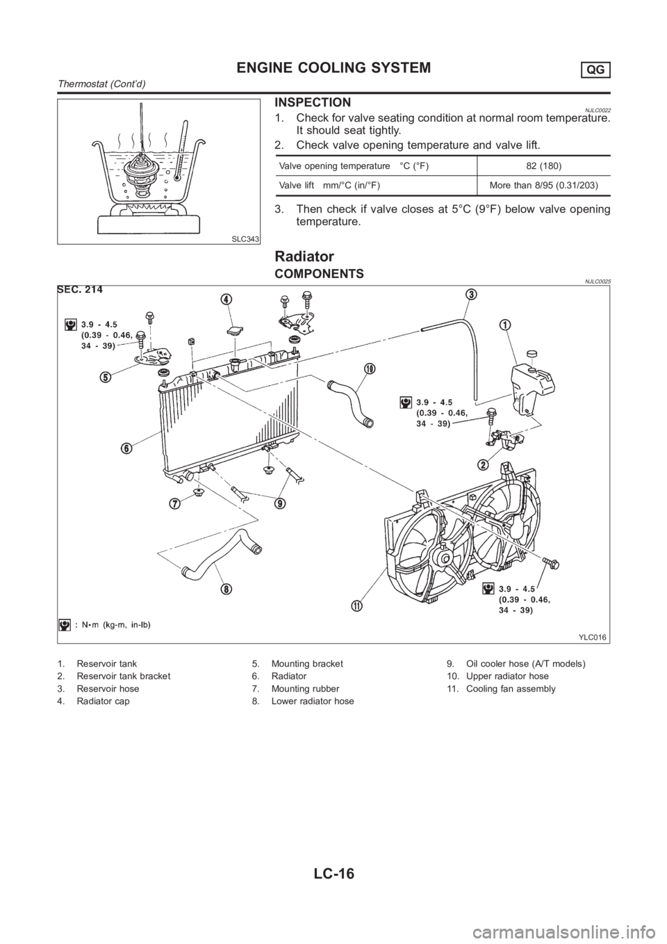
SLC343
INSPECTIONNJLC00221. Check for valve seating condition at normal room temperature.
It should seat tightly.
2. Check valve opening temperature and valve lift.
Valve opening temperature °C (°F) 82 (180)
Valve lift mm/°C (in/°F) More than 8/95 (0.31/203)
3. Then check if valve closes at 5°C (9°F) below valve opening
temperature.
Radiator
COMPONENTSNJLC0025
YLC016
1. Reservoir tank
2. Reservoir tank bracket
3. Reservoir hose
4. Radiator cap5. Mounting bracket
6. Radiator
7. Mounting rubber
8. Lower radiator hose9. Oil cooler hose (A/T models)
10. Upper radiator hose
11. Cooling fan assembly
ENGINE COOLING SYSTEMQG
Thermostat (Cont’d)
LC-16