speed NISSAN ALMERA N16 2003 Electronic Repair Manual
[x] Cancel search | Manufacturer: NISSAN, Model Year: 2003, Model line: ALMERA N16, Model: NISSAN ALMERA N16 2003Pages: 3189, PDF Size: 54.76 MB
Page 2051 of 3189
TROUBLE DIAGNOSIS
ATC-71
C
D
E
F
G
H
I
K
L
MA
B
AT C
In the most extreme case (very low ambient) the blower starting delay will be 150 seconds as described
above. After this delay, the blower will operate at low speed until the engine coolant temperature rises above
56°C (133°F), at which time the blower speed will increase to the objective speed.
Start Up From Usual or HOT SOAK Condition (Automatic mode)
The blower will begin operation momentarily after the A/C button is pushed. The blower speed will gradually
rise to the objective speed over a time period of 3 seconds or less (actual time depends on the objective
blower speed).
Blower Speed Compensation
Sunload
When the in-vehicle temperature and the set temperature are very close, the blower will be operating at low
speed. The low speed will vary depending on the sunload. During conditions of low or no sunload, the blower
low speed is usual low speed (approx. 4V). During high sunload conditions, the auto amp causes the blower
fan speed to increase.(Approx. 7V)
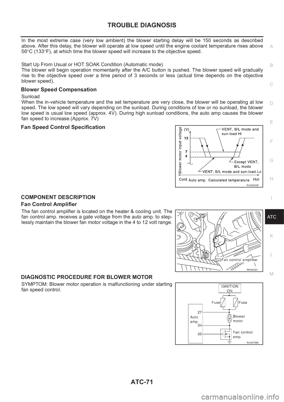
Fan Speed Control Specification
COMPONENT DESCRIPTION
Fan Control Amplifier
The fan control amplifier is located on the heater & cooling unit. The
fan control amp. receives a gate voltage from the auto amp. to step-
lessly maintain the blower fan motor voltage in the 4 to 12 volt range.
DIAGNOSTIC PROCEDURE FOR BLOWER MOTOR
SYMPTOM: Blower motor operation is malfunctioning under starting
fan speed control.
RJIA0522E
RHA625H
RJIA0786E
Page 2052 of 3189
ATC-72
TROUBLE DIAGNOSIS
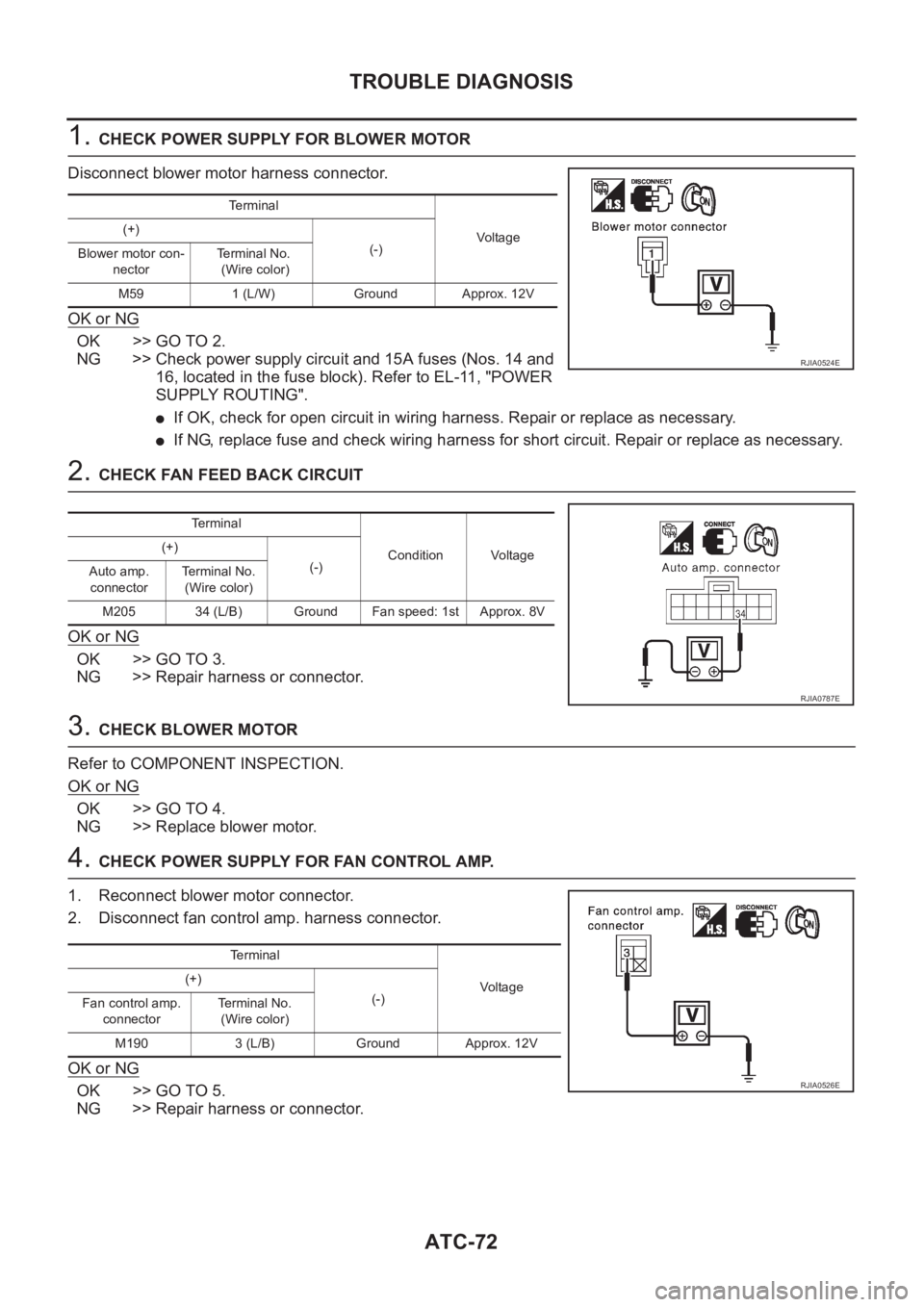
1. CHECK POWER SUPPLY FOR BLOWER MOTOR
Disconnect blower motor harness connector.
OK or NG
OK >> GO TO 2.
NG >> Check power supply circuit and 15A fuses (Nos. 14 and
16, located in the fuse block). Refer to EL-11, "POWER
SUPPLY ROUTING".
●If OK, check for open circuit in wiring harness. Repair or replace as necessary.
●If NG, replace fuse and check wiring harness for short circuit. Repair or replace as necessary.
2. CHECK FAN FEED BACK CIRCUIT
OK or NG
OK >> GO TO 3.
NG >> Repair harness or connector.
3. CHECK BLOWER MOTOR
Refer to COMPONENT INSPECTION.
OK or NG
OK >> GO TO 4.
NG >> Replace blower motor.
4. CHECK POWER SUPPLY FOR FAN CONTROL AMP.
1. Reconnect blower motor connector.
2. Disconnect fan control amp. harness connector.
OK or NG
OK >> GO TO 5.
NG >> Repair harness or connector.
Terminal
Vo l ta g e (+)
(-)
Blower motor con-
nectorTerminal No.
(Wire color)
M59 1 (L/W) Ground Approx. 12V
RJIA0524E
Te r m i n a l
Condition Voltage (+)
(-)
Auto amp.
connectorTerminal No.
(Wire color)
M205 34 (L/B) Ground Fan speed: 1st Approx. 8V
RJIA0787E
Te r m i n a l
Voltag e (+)
(-)
Fan control amp.
connectorTerminal No.
(Wire color)
M190 3 (L/B) Ground Approx. 12V
RJIA0526E
Page 2053 of 3189
TROUBLE DIAGNOSIS
ATC-73
C
D
E
F
G
H
I
K
L
MA
B
AT C
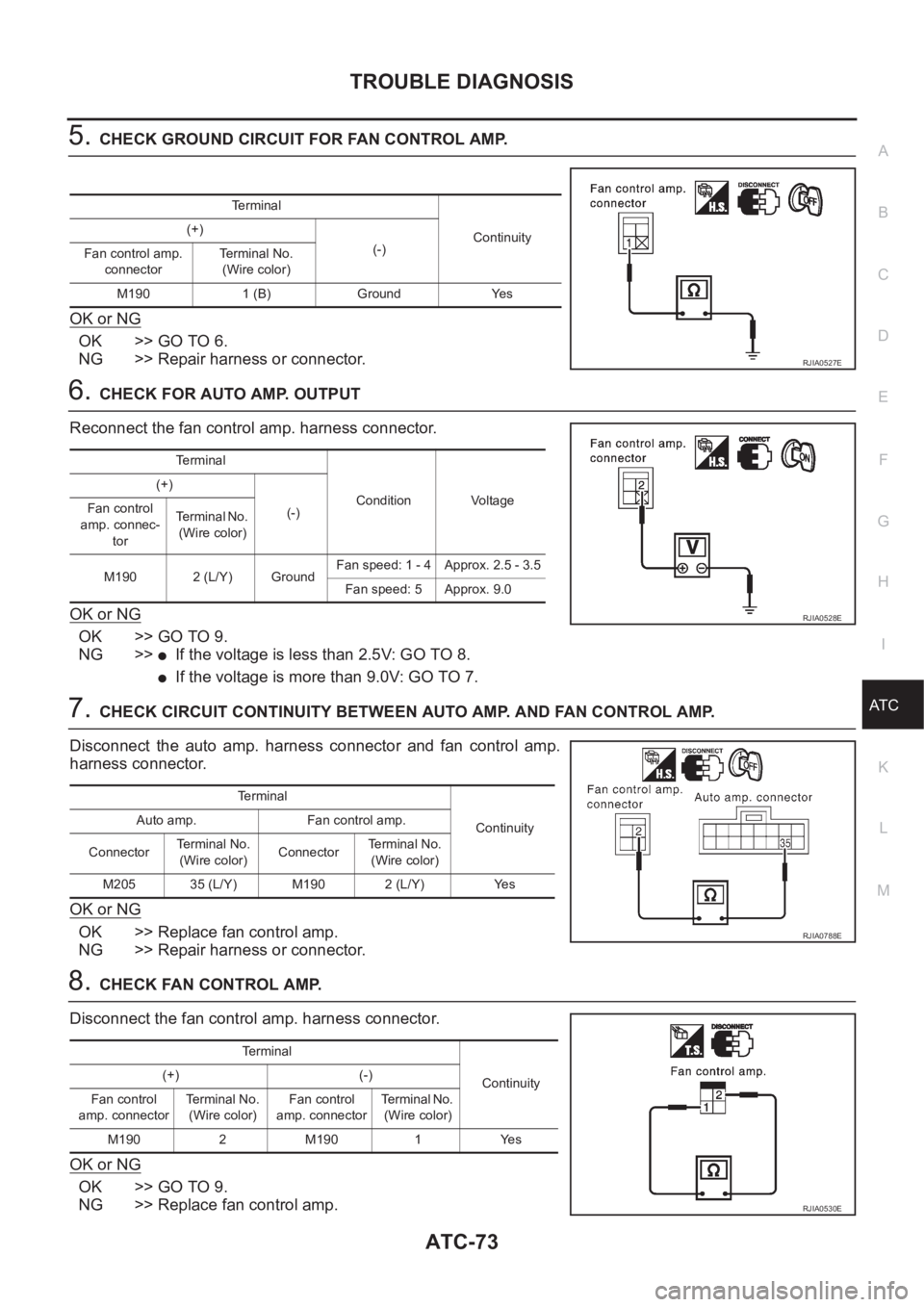
5.CHECK GROUND CIRCUIT FOR FAN CONTROL AMP.
OK or NG
OK >> GO TO 6.
NG >> Repair harness or connector.
6.CHECK FOR AUTO AMP. OUTPUT
Reconnect the fan control amp. harness connector.
OK or NG
OK >> GO TO 9.
NG >>
●If the voltage is less than 2.5V: GO TO 8.
●If the voltage is more than 9.0V: GO TO 7.
7.CHECK CIRCUIT CONTINUITY BETWEEN AUTO AMP. AND FAN CONTROL AMP.
Disconnect the auto amp. harness connector and fan control amp.
harness connector.
OK or NG
OK >> Replace fan control amp.
NG >> Repair harness or connector.
8.CHECK FAN CONTROL AMP.
Disconnect the fan control amp. harness connector.
OK or NG
OK >> GO TO 9.
NG >> Replace fan control amp.
Te r m i n a l
Continuity (+)
(-)
Fan control amp.
connectorTerminal No.
(Wire color)
M190 1 (B) Ground Yes
RJIA0527E
Terminal
Condition Voltage (+)
(-) Fan control
amp. connec-
torTe r m i n a l N o .
(Wire color)
M190 2 (L/Y) GroundFan speed: 1 - 4 Approx. 2.5 - 3.5
Fan speed: 5 Approx. 9.0
RJIA0528E
Terminal
Continuity Auto amp. Fan control amp.
ConnectorTerminal No.
(Wire color)Connector Terminal No.
(Wire color)
M205 35 (L/Y) M190 2 (L/Y) Yes
RJIA0788E
Terminal
Continuity (+) (-)
Fan control
amp. connectorTe r m i n a l N o .
(Wire color)Fan control
amp. connectorTerminal No.
(Wire color)
M190 2 M190 1 Yes
RJIA0530E
Page 2070 of 3189
ATC-90
TROUBLE DIAGNOSIS
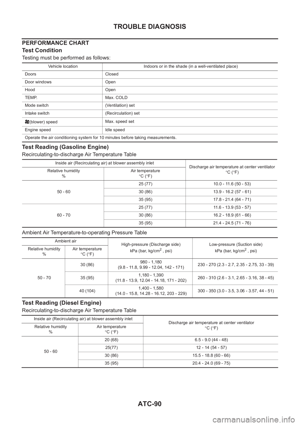
PERFORMANCE CHART
Test Condition
Testing must be performed as follows:
Test Reading (Gasoline Engine)
Recirculating-to-discharge Air Temperature Table
Ambient Air Temperature-to-operating Pressure Table
Test Reading (Diesel Engine)
Recirculating-to-discharge Air Temperature Table
Vehicle location Indoors or in the shade (in a well-ventilated place)
Doors Closed
Door windows Open
Hood Open
TEMP. Max. COLD
Mode switch (Ventilation) set
Intake switch (Recirculation) set
(blower) speedMax. speed set
Engine speed Idle speed
Operate the air conditioning system for 10 minutes before taking measurements.
Inside air (Recirculating air) at blower assembly inlet
Discharge air temperature at center ventilator
°C (°F) Relative humidity
%Air temperature
°C (°F)
50 - 6025 (77) 10.0 - 11.6 (50 - 53)
30 (86) 13.9 - 16.2 (57 - 61)
35 (95) 17.8 - 21.4 (64 - 71)
60 - 7025 (77) 11.6 - 13.9 (53 - 57)
30 (86) 16.2 - 18.9 (61 - 66)
35 (95) 21.4 - 24.5 (71 - 76)
Ambient air
High-pressure (Discharge side)
kPa (bar, kg/cm
2 , psi)Low-pressure (Suction side)
kPa (bar, kg/cm2 , psi) Relative humidity
%Air temperature
°C (°F)
50 - 7030 (86)980 - 1,180
(9.8 - 11.8, 9.99 - 12.04, 142 - 171)230 - 270 (2.3 - 2.7, 2.35 - 2.75, 33 - 39)
35 (95)1,180 - 1,390
(11.8 - 13.9, 12.04 - 14.18, 171 - 202)260 - 310 (2.6 - 3.1, 2.65 - 3.16, 38 - 45)
40 (104)1,400 - 1,580
(14.0 - 15.8, 14.28 - 16.12, 203 - 229)300 - 350 (3.0 - 3.5, 3.06 - 3.57, 44 - 51)
Inside air (Recirculating air) at blower assembly inlet
Discharge air temperature at center ventilator
°C (°F) Relative humidity
%Air temperature
°C (°F)
50 - 6020 (68) 6.5 - 9.0 (44 - 48)
25(77) 12 - 14 (54 - 57)
30 (86) 15.5 - 18.8 (60 - 66)
35 (95) 20.4 - 24.0 (69 - 75)
Page 2080 of 3189
ATC-100
TROUBLE DIAGNOSIS
Ambient Sensor Circuit
EJS001ZV
COMPONENT DESCRIPTION
Ambient Sensor
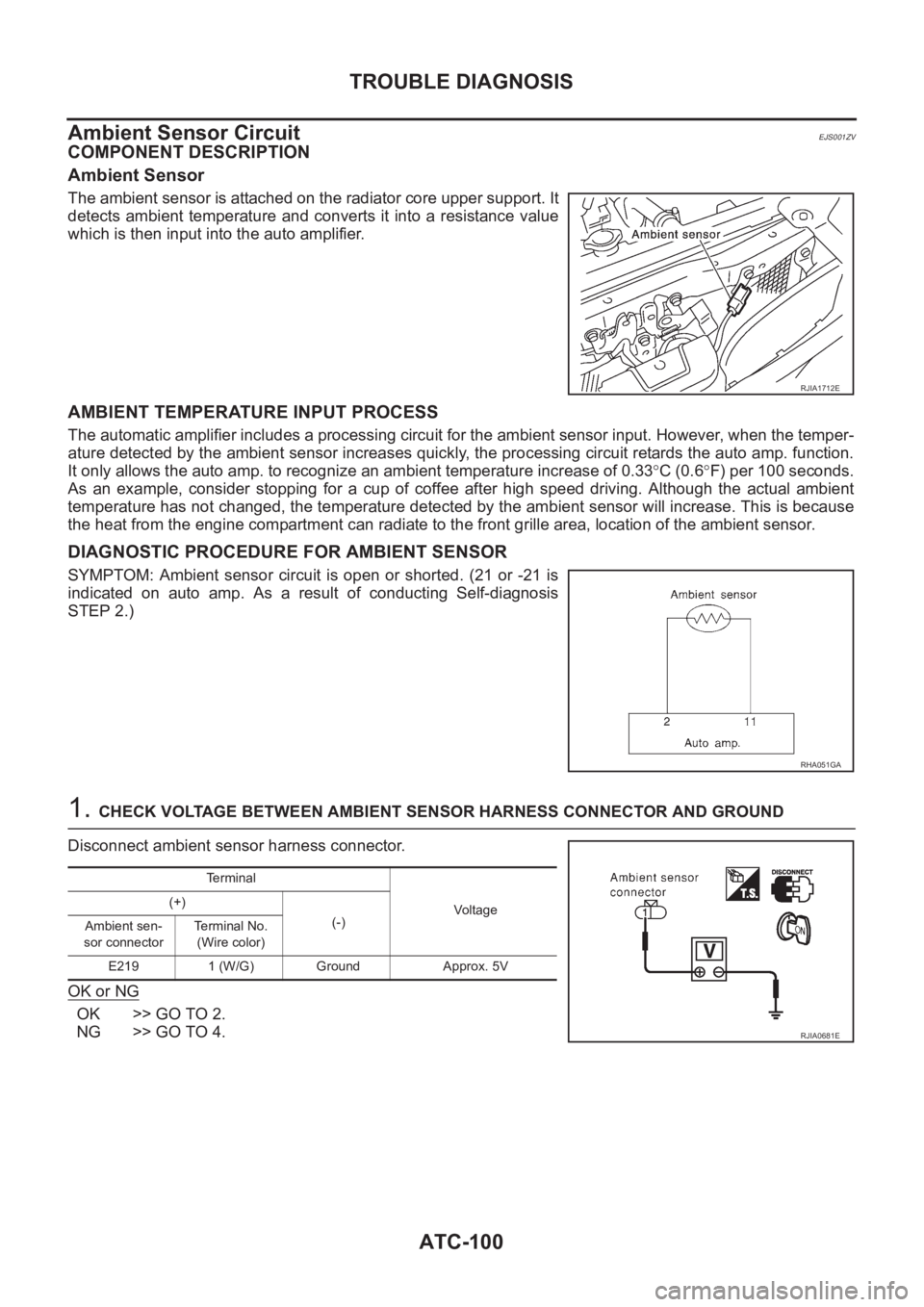
The ambient sensor is attached on the radiator core upper support. It
detects ambient temperature and converts it into a resistance value
which is then input into the auto amplifier.
AMBIENT TEMPERATURE INPUT PROCESS
The automatic amplifier includes a processing circuit for the ambient sensor input. However, when the temper-
ature detected by the ambient sensor increases quickly, the processing circuit retards the auto amp. function.
It only allows the auto amp. to recognize an ambient temperature increase of 0.33°C (0.6°F) per 100 seconds.
As an example, consider stopping for a cup of coffee after high speed driving. Although the actual ambient
temperature has not changed, the temperature detected by the ambient sensor will increase. This is because
the heat from the engine compartment can radiate to the front grille area, location of the ambient sensor.
DIAGNOSTIC PROCEDURE FOR AMBIENT SENSOR
SYMPTOM: Ambient sensor circuit is open or shorted. (21 or -21 is
indicated on auto amp. As a result of conducting Self-diagnosis
STEP 2.)
1. CHECK VOLTAGE BETWEEN AMBIENT SENSOR HARNESS CONNECTOR AND GROUND
Disconnect ambient sensor harness connector.
OK or NG
OK >> GO TO 2.
NG >> GO TO 4.
RJIA1712E
RHA051GA
Terminal
Voltage (+)
(-)
Ambient sen-
sor connectorTerminal No.
(Wire color)
E219 1 (W/G) Ground Approx. 5V
RJIA0681E
Page 2127 of 3189
REFRIGERANT LINES
ATC-147
C
D
E
F
G
H
I
K
L
MA
B
AT C
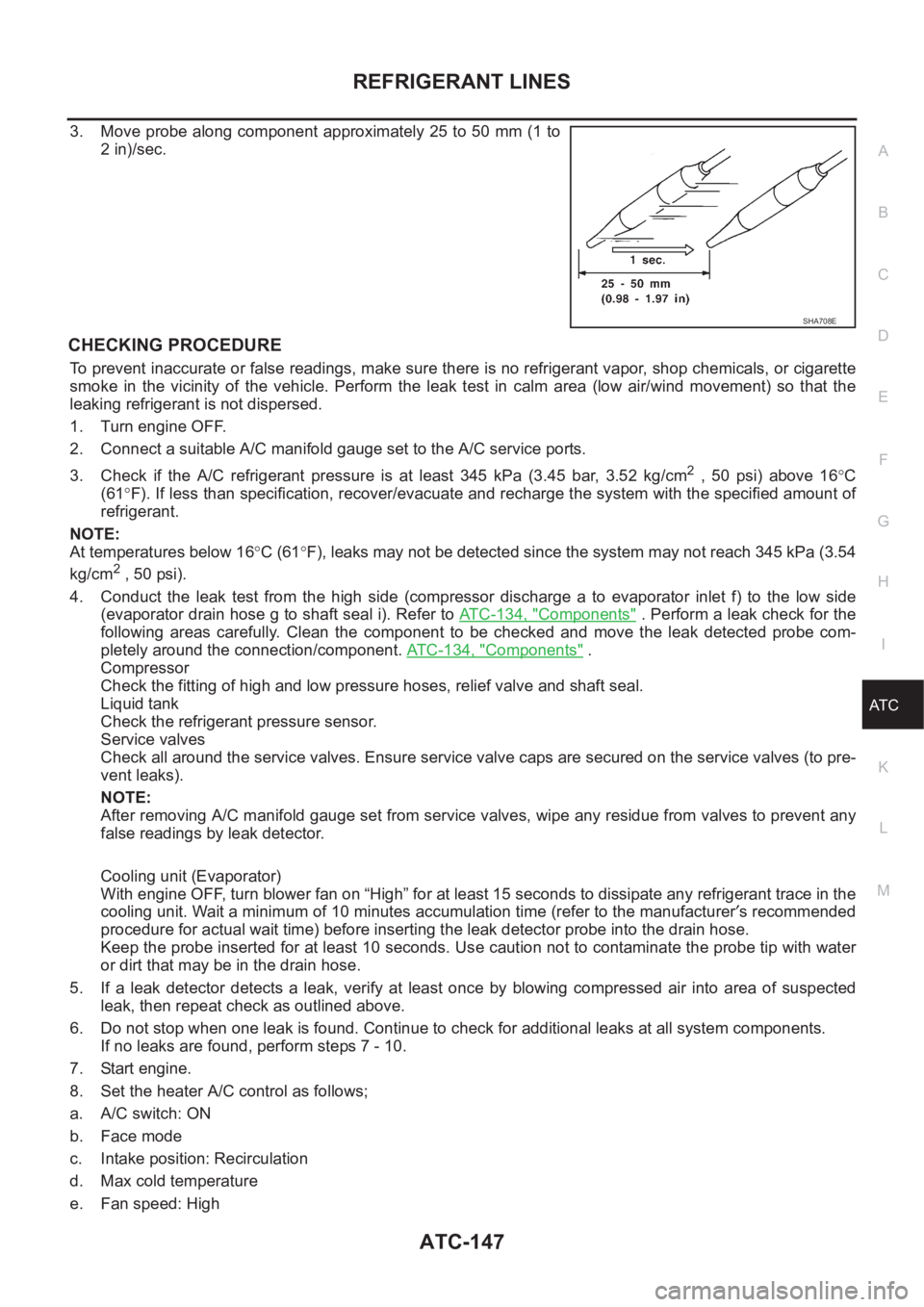
3. Move probe along component approximately 25 to 50 mm (1 to
2 in)/sec.
CHECKING PROCEDURE
To prevent inaccurate or false readings, make sure there is no refrigerant vapor, shop chemicals, or cigarette
smoke in the vicinity of the vehicle. Perform the leak test in calm area (low air/wind movement) so that the
leaking refrigerant is not dispersed.
1. Turn engine OFF.
2. Connect a suitable A/C manifold gauge set to the A/C service ports.
3. Check if the A/C refrigerant pressure is at least 345 kPa (3.45 bar, 3.52 kg/cm
2 , 50 psi) above 16°C
(61°F). If less than specification, recover/evacuate and recharge the system with the specified amount of
refrigerant.
NOTE:
At temperatures below 16°C (61°F), leaks may not be detected since the system may not reach 345 kPa (3.54
kg/cm
2 , 50 psi).
4. Conduct the leak test from the high side (compressor discharge a to evaporator inlet f) to the low side
(evaporator drain hose g to shaft seal i). Refer to AT C - 1 3 4 , "
Components" . Perform a leak check for the
following areas carefully. Clean the component to be checked and move the leak detected probe com-
pletely around the connection/component. ATC-134, "
Components" .
Compressor
Check the fitting of high and low pressure hoses, relief valve and shaft seal.
Liquid tank
Check the refrigerant pressure sensor.
Service valves
Check all around the service valves. Ensure service valve caps are secured on the service valves (to pre-
vent leaks).
NOTE:
After removing A/C manifold gauge set from service valves, wipe any residue from valves to prevent any
false readings by leak detector.
Cooling unit (Evaporator)
With engine OFF, turn blower fan on “High” for at least 15 seconds to dissipate any refrigerant trace in the
cooling unit. Wait a minimum of 10 minutes accumulation time (refer to the manufacturer′s recommended
procedure for actual wait time) before inserting the leak detector probe into the drain hose.
Keep the probe inserted for at least 10 seconds. Use caution not to contaminate the probe tip with water
or dirt that may be in the drain hose.
5. If a leak detector detects a leak, verify at least once by blowing compressed air into area of suspected
leak, then repeat check as outlined above.
6. Do not stop when one leak is found. Continue to check for additional leaks at all system components.
If no leaks are found, perform steps 7 - 10.
7. Start engine.
8. Set the heater A/C control as follows;
a. A/C switch: ON
b. Face mode
c. Intake position: Recirculation
d. Max cold temperature
e. Fan speed: High
SHA708E
Page 2129 of 3189
SERVICE DATA AND SPECIFICATIONS (SDS)
ATC-149
C
D
E
F
G
H
I
K
L
MA
B
AT C
SERVICE DATA AND SPECIFICATIONS (SDS)PFP:00030
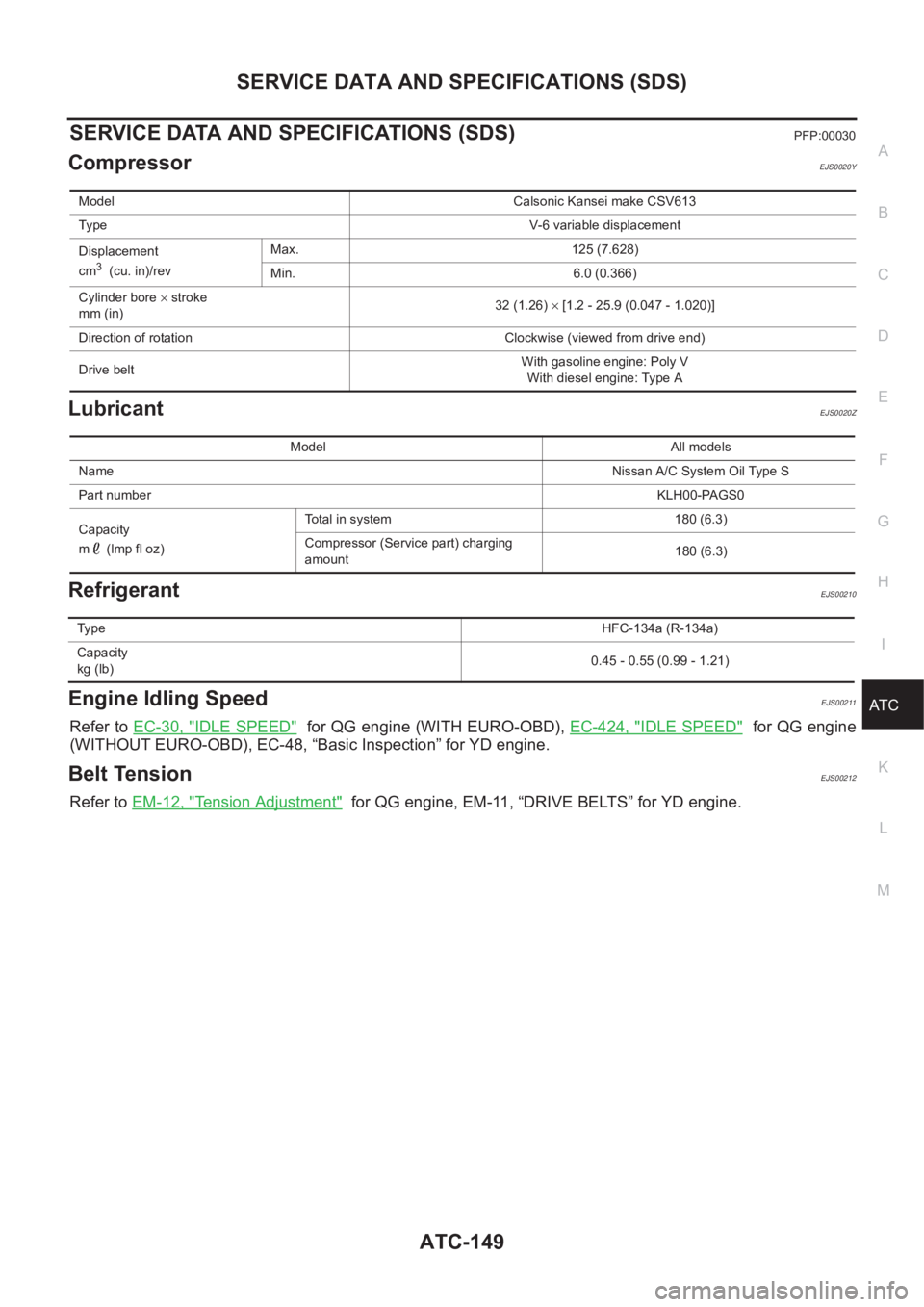
CompressorEJS0020Y
LubricantEJS0020Z
RefrigerantEJS00210
Engine Idling SpeedEJS00211
Refer to EC-30, "IDLE SPEED" for QG engine (WITH EURO-OBD), EC-424, "IDLE SPEED" for QG engine
(WITHOUT EURO-OBD), EC-48, “Basic Inspection” for YD engine.
Belt TensionEJS00212
Refer to EM-12, "Tension Adjustment" for QG engine, EM-11, “DRIVE BELTS” for YD engine.
Model Calsonic Kansei make CSV613
TypeV-6 variable displacement
Displacement
cm
3 (cu. in)/revMax. 125 (7.628)
Min. 6.0 (0.366)
Cylinder bore × stroke
mm (in)32 (1.26) × [1.2 - 25.9 (0.047 - 1.020)]
Direction of rotation Clockwise (viewed from drive end)
Drive beltWith gasoline engine: Poly V
With diesel engine: Type A
Model All models
NameNissan A/C System Oil Type S
Part numberKLH00-PAGS0
Capacity
m (lmp fl oz)Total in system 180 (6.3)
Compressor (Service part) charging
amount180 (6.3)
Ty p eHFC-134a (R-134a)
Capacity
kg (lb)0.45 - 0.55 (0.99 - 1.21)
Page 2229 of 3189
PurposeNJBR0082The ABS consists of electronic and hydraulic components. It allows for control of braking force so that lock-
ing of the wheels can be avoided.
The ABS:
1) Ensures proper tracking performance through steering wheel operation.
2) Enables obstacles to be avoided through steering wheel operation.
3) Ensures vehicle stability by preventing flat spins.
ABS (Anti-Lock Brake System) OperationNJBR0083When the vehicle speed is less than 10 km/h (6 MPH) this system does not work.
The Anti-Lock Brake System (ABS) has self-test capabilities. The system turns on the ABS warning lamp
for 1 second after turning the ignition switch ON. The system performs another test the first time the vehicle
reaches 6 km/h (4 MPH). A mechanical noise may be heard as the ABS performs a self-test. This is a
normal part of the self-test feature. If a malfunction is found during thischeck, the ABS warning lamp will
come on.
During ABS operation, a mechanical noise may be heard. This is a normal condition.
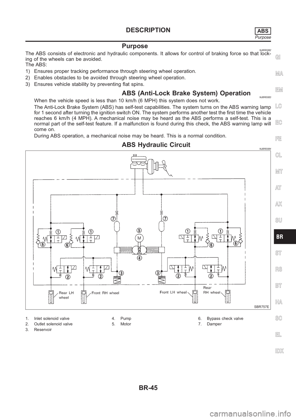
ABS Hydraulic CircuitNJBR0084
SBR757E
1. Inlet solenoid valve
2. Outlet solenoid valve
3. Reservoir4. Pump
5. Motor6. Bypass check valve
7. Damper
GI
MA
EM
LC
EC
FE
CL
MT
AT
AX
SU
ST
RS
BT
HA
SC
EL
IDX
DESCRIPTIONABS
Purpose
BR-45
Page 2230 of 3189
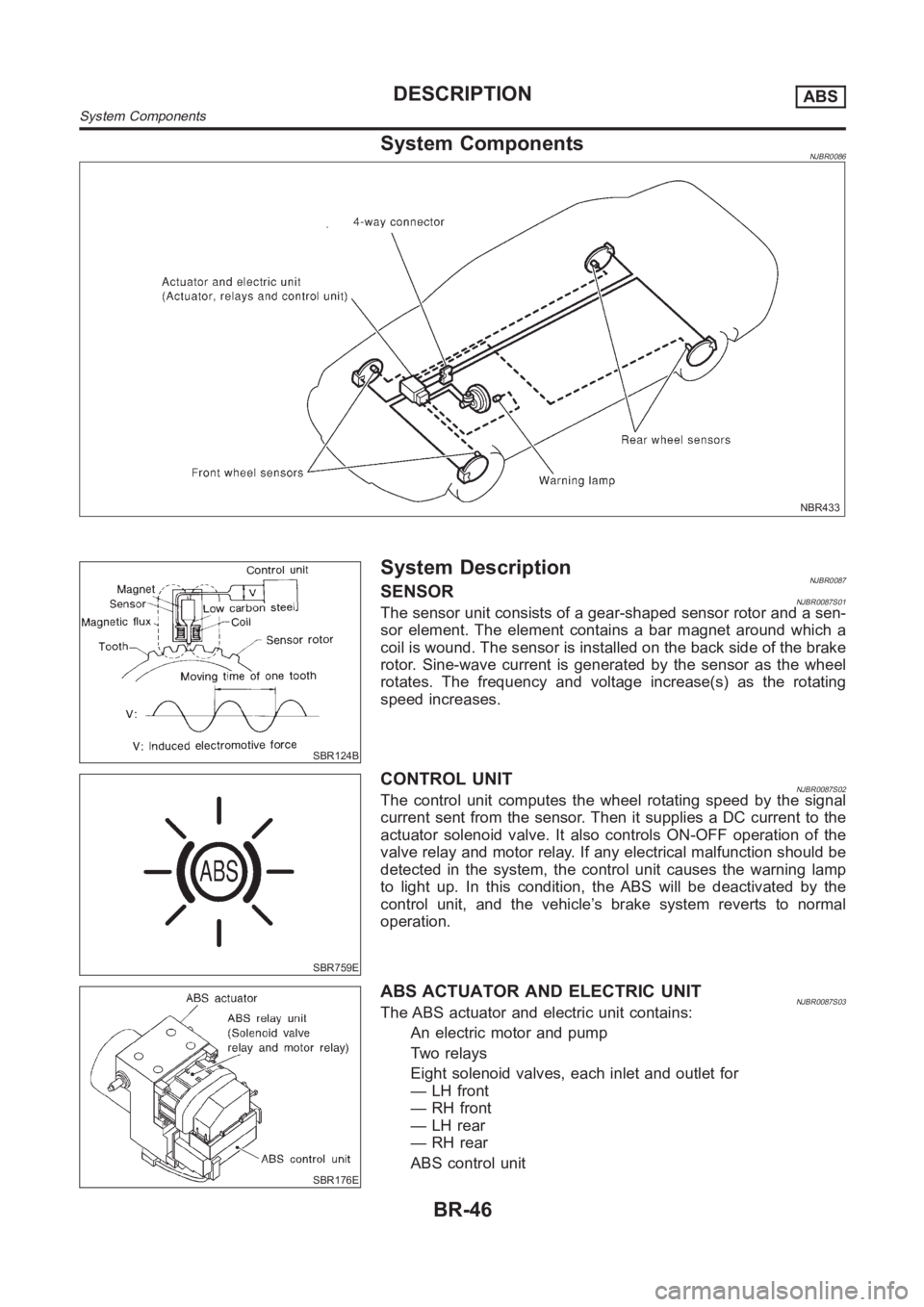
System ComponentsNJBR0086
NBR433
SBR124B
System DescriptionNJBR0087SENSORNJBR0087S01The sensor unit consists of a gear-shaped sensor rotor and a sen-
sor element. The element contains a bar magnet around which a
coil is wound. The sensor is installed on the back side of the brake
rotor. Sine-wave current is generated by the sensor as the wheel
rotates. The frequency and voltage increase(s) as the rotating
speed increases.
SBR759E
CONTROL UNITNJBR0087S02The control unit computes the wheel rotating speed by the signal
current sent from the sensor. Then it supplies a DC current to the
actuator solenoid valve. It also controls ON-OFF operation of the
valve relay and motor relay. If any electrical malfunction should be
detected in the system, the control unit causes the warning lamp
to light up. In this condition, the ABS will be deactivated by the
control unit, and the vehicle’s brake system reverts to normal
operation.
SBR176E
ABS ACTUATOR AND ELECTRIC UNITNJBR0087S03The ABS actuator and electric unit contains:
An electric motor and pump
Two relays
Eight solenoid valves, each inlet and outlet for
— LH front
—RHfront
— LH rear
— RH rear
ABS control unit
DESCRIPTIONABS
System Components
BR-46
Page 2238 of 3189
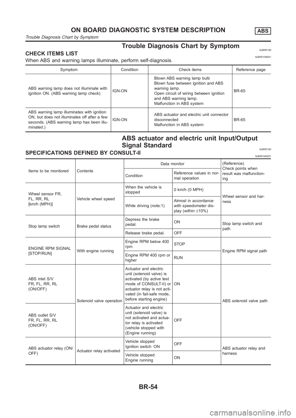
Trouble Diagnosis Chart by SymptomNJBR0159CHECK ITEMS LISTNJBR0159S01When ABS and warning lamps illuminate, perform self-diagnosis.
Symptom Condition Check items Reference page
ABS warning lamp does not illuminate with
ignition ON. (ABS warning lamp check)IGN-ONBlown ABS warning lamp bulb
Blown fuse between ignition and ABS
warning lamp.
Open circuit of wiring between ignition
and ABS warning lamp.
Malfunction in ABS systemBR-65
ABS warning lamp illuminates with ignition
ON, but does not illuminates off after a few
seconds. (ABS warning lamp has been illu-
minated.)IGN-ONABS actuator and electric unit connector
disconnected
Malfunction in ABS systemBR-65
ABS actuator and electric unit Input/Output
Signal Standard
NJBR0160SPECIFICATIONS DEFINED BY CONSULT-IINJBR0160S01
Items to be monitored ContentsData monitor(Reference)
Check points when
result was malfunction-
ing ConditionReference values in nor-
mal operation
Wheel sensor FR,
FL, RR, RL
[km/h (MPH)]Vehicle wheel speedWhen the vehicle is
stopped0 km/h (0 MPH)
Wheel sensor and har-
ness
While driving (note:1)Almost in accordance
with speedometer dis-
play (within±10%)
Stop lamp switch Brake pedal statusDepress the brake
pedal.ON
Stop lamp switch and
path
Release brake pedal. OFF
ENGINE RPM SIGNAL
[STOP/RUN]With engine runningEngine RPM below 400
rpmSTOP
Engine RPM signal path
Engine RPM 400 rpm or
higherRUN
ABS inlet S/V
FR, FL, RR, RL
(ON/OFF)
Solenoid valve operationActuator and electric
unit (solenoid valve) is
activated (by active test
mode of CONSULT-II) or
actuator relay is not acti-
vated (in fail-safe mode,
before starting engine)ON
ABS solenoid valve path
ABS outlet S/V
FR, FL, RR, RL
(ON/OFF)Actuator and electric
unit (solenoid valve) is
not activated and actua-
tor relay is activated
(vehicle stopped with
(Engine running)OFF
ABS actuator relay (ON/
OFF)Actuator relay activatedVehicle stopped
Ignition switch ONOFF
ABS actuator relay and
harness
Vehicle stopped
Engine runningON
ON BOARD DIAGNOSTIC SYSTEM DESCRIPTIONABS
Trouble Diagnosis Chart by Symptom
BR-54