speed NISSAN ALMERA N16 2003 Electronic Repair Manual
[x] Cancel search | Manufacturer: NISSAN, Model Year: 2003, Model line: ALMERA N16, Model: NISSAN ALMERA N16 2003Pages: 3189, PDF Size: 54.76 MB
Page 2239 of 3189
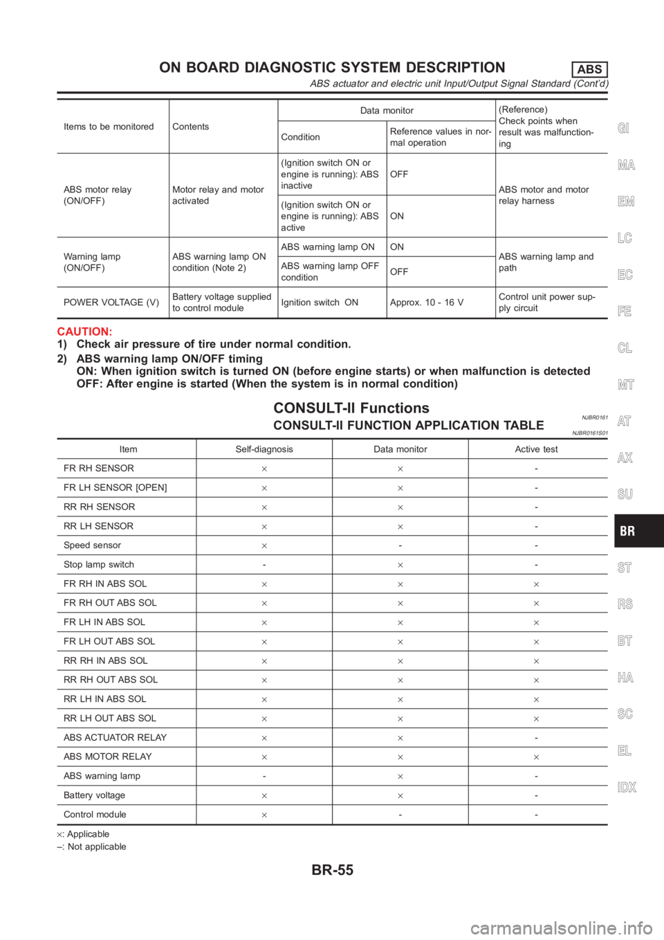
Items to be monitored ContentsData monitor(Reference)
Check points when
result was malfunction-
ing ConditionReference values in nor-
mal operation
ABS motor relay
(ON/OFF)Motor relay and motor
activated(Ignition switch ON or
engine is running): ABS
inactiveOFF
ABS motor and motor
relay harness
(Ignition switch ON or
engine is running): ABS
activeON
Warning lamp
(ON/OFF)ABS warning lamp ON
condition (Note 2)ABS warning lamp ON ON
ABS warning lamp and
path ABS warning lamp OFF
conditionOFF
POWER VOLTAGE (V)Battery voltage supplied
to control moduleIgnition switch ON Approx. 10 - 16 VControl unit power sup-
ply circuit
CAUTION:
1) Check air pressure of tire under normal condition.
2) ABS warning lamp ON/OFF timing
ON: When ignition switch is turned ON (before engine starts) or when malfunction is detected
OFF: After engine is started (When the system is in normal condition)
CONSULT-II FunctionsNJBR0161CONSULT-II FUNCTION APPLICATION TABLENJBR0161S01
Item Self-diagnosis Data monitor Active test
FR RH SENSOR××-
FR LH SENSOR [OPEN]××-
RR RH SENSOR××-
RR LH SENSOR××-
Speed sensor×--
Stop lamp switch -×-
FR RH IN ABS SOL×××
FR RH OUT ABS SOL×××
FR LH IN ABS SOL×××
FR LH OUT ABS SOL×××
RR RH IN ABS SOL×××
RR RH OUT ABS SOL×××
RR LH IN ABS SOL×××
RR LH OUT ABS SOL×××
ABS ACTUATOR RELAY××-
ABS MOTOR RELAY×××
ABS warning lamp -×-
Battery voltage××-
Control module×--
×: Applicable
–: Not applicable
GI
MA
EM
LC
EC
FE
CL
MT
AT
AX
SU
ST
RS
BT
HA
SC
EL
IDX
ON BOARD DIAGNOSTIC SYSTEM DESCRIPTIONABS
ABS actuator and electric unit Input/Output Signal Standard (Cont’d)
BR-55
Page 2242 of 3189
![NISSAN ALMERA N16 2003 Electronic Repair Manual Faulty lines Malfunction detecting condition Check harness
RR RH OUT ABS SOL
[OPEN] [SHORT]At RH rear wheel ABS outlet solenoid valve, following
conditions occur: open circuit, output voltage is abnor NISSAN ALMERA N16 2003 Electronic Repair Manual Faulty lines Malfunction detecting condition Check harness
RR RH OUT ABS SOL
[OPEN] [SHORT]At RH rear wheel ABS outlet solenoid valve, following
conditions occur: open circuit, output voltage is abnor](/img/5/57350/w960_57350-2241.png)
Faulty lines Malfunction detecting condition Check harness
RR RH OUT ABS SOL
[OPEN] [SHORT]At RH rear wheel ABS outlet solenoid valve, following
conditions occur: open circuit, output voltage is abnor-
mally lower or higher than control value by short to
ground on control line.
ABS solenoid valve and actua-
tor relay harness
RR LH OUT ABS SOL
[OPEN] [SHORT]At LH rear wheel ABS outlet solenoid valve, following
conditions occur: open circuit, output voltage is abnor-
mally lower or higher than control value by short to
ground on control line.
ABS motor [ON error]ABS actuator motor turned ON when the ABS motor is
controlled OFF.
ABS motor relay and harness
ABS motor [OFF error]ABS actuator motor turned OFF when the ABS motor is
controlled ON.
ABS actuator relay [ON error] ABS actuator relay turned ON wheel it is controlled OFF.
ABS actuator relay and har-
ness ABS ACTUATOR RELAY
[OFF abnormal]ABS actuator relay turned OFF wheel it is controlled ON.
BATTERY VOLTAGE [ABNORMAL]Power source voltage supplied to ABS actuator and elec-
tric unit is abnormally low.ABS actuator and electric unit
power supply circuit
CONTROL UNITFunction of calculation in ABS actuator and electric unit
has failed.ABS actuator and electric unit,
power and ground circuits
(Note 1): When vehicle was stuck on slippery road, and spin its wheels for Approx. 10 - 80 seconds (the period depends on vehicle
speed). ABS warning lamp may come on. However, this is not abnormal.
(Note 2): Repair short circuit in sensor. ABS warning lamp will come on whenignition switch is turned ON. According to self-diagnosis
operation procedure, drive vehicle at Approx. 30 km/h (19 MPH). Then checkABS warning lamp goes out in about one minute.
DATA MONITORNJBR0161S03For details of data monitor function, refer to CONSULT-II
Instruction Manual.
Operation ProcedureNJBR0161S03011. Turn the ignition switch to OFF.
2. Connect CONSULT-II connector to data link connector on
vehicle.
3. Turn ignition switch ON.
MBIB0233E
4. Touch “START (NISSAN BASED VHCL)” on the display.
ON BOARD DIAGNOSTIC SYSTEM DESCRIPTIONABS
CONSULT-II Functions (Cont’d)
BR-58
Page 2243 of 3189
PBR385C
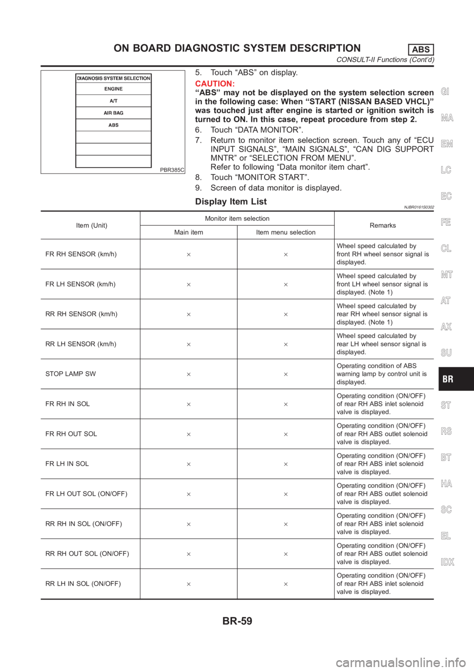
5. Touch “ABS” on display.
CAUTION:
“ABS” may not be displayed on the system selection screen
in the following case: When “START (NISSAN BASED VHCL)”
was touched just after engine is started or ignition switch is
turned to ON. In this case, repeat procedure from step 2.
6. Touch “DATA MONITOR”.
7. Return to monitor item selection screen. Touch any of “ECU
INPUT SIGNALS”, “MAIN SIGNALS”, “CAN DIG SUPPORT
MNTR” or “SELECTION FROM MENU”.
Refer to following “Data monitor item chart”.
8. Touch “MONITOR START”.
9. Screen of data monitor is displayed.
Display Item ListNJBR0161S0302
Item (Unit)Monitor item selection
Remarks
Main item Item menu selection
FR RH SENSOR (km/h)××Wheel speed calculated by
front RH wheel sensor signal is
displayed.
FR LH SENSOR (km/h)××Wheel speed calculated by
front LH wheel sensor signal is
displayed. (Note 1)
RR RH SENSOR (km/h)××Wheel speed calculated by
rear RH wheel sensor signal is
displayed. (Note 1)
RR LH SENSOR (km/h)××Wheel speed calculated by
rear LH wheel sensor signal is
displayed.
STOP LAMP SW××Operating condition of ABS
warning lamp by control unit is
displayed.
FR RH IN SOL××Operating condition (ON/OFF)
of rear RH ABS inlet solenoid
valve is displayed.
FR RH OUT SOL××Operating condition (ON/OFF)
of rear RH ABS outlet solenoid
valve is displayed.
FR LH IN SOL××Operating condition (ON/OFF)
of rear RH ABS inlet solenoid
valve is displayed.
FR LH OUT SOL (ON/OFF)××Operating condition (ON/OFF)
of rear RH ABS outlet solenoid
valve is displayed.
RR RH IN SOL (ON/OFF)××Operating condition (ON/OFF)
of rear RH ABS inlet solenoid
valve is displayed.
RR RH OUT SOL (ON/OFF)××Operating condition (ON/OFF)
of rear RH ABS outlet solenoid
valve is displayed.
RR LH IN SOL (ON/OFF)××Operating condition (ON/OFF)
of rear RH ABS inlet solenoid
valve is displayed.
GI
MA
EM
LC
EC
FE
CL
MT
AT
AX
SU
ST
RS
BT
HA
SC
EL
IDX
ON BOARD DIAGNOSTIC SYSTEM DESCRIPTIONABS
CONSULT-II Functions (Cont’d)
BR-59
Page 2252 of 3189
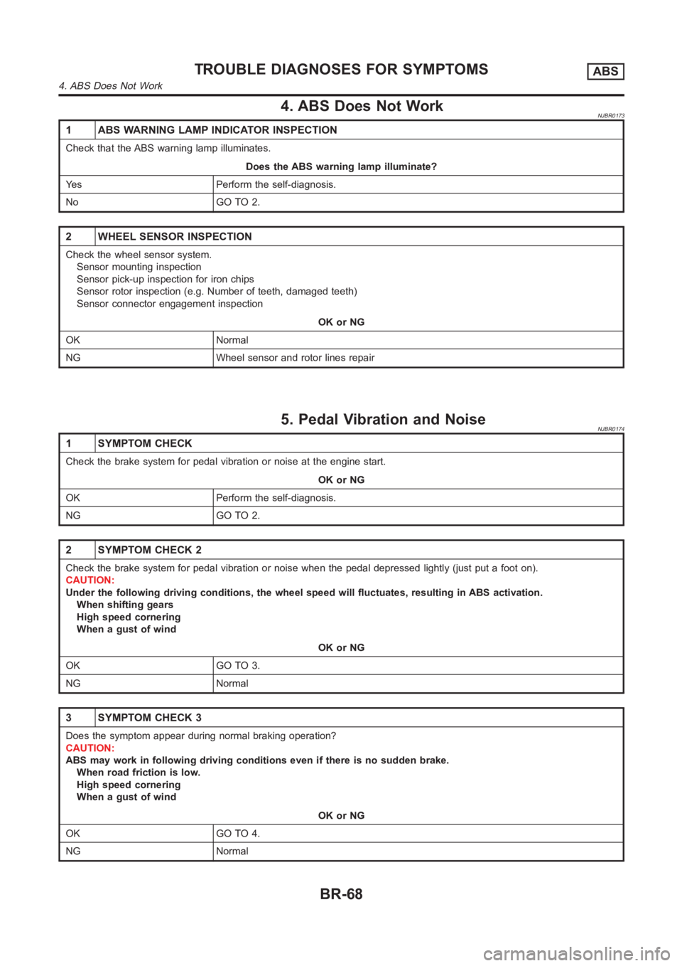
4. ABS Does Not WorkNJBR0173
1 ABS WARNING LAMP INDICATOR INSPECTION
Check that the ABS warning lamp illuminates.
Does the ABS warning lamp illuminate?
Yes Perform the self-diagnosis.
No GO TO 2.
2 WHEEL SENSOR INSPECTION
Check the wheel sensor system.
Sensor mounting inspection
Sensor pick-up inspection for iron chips
Sensor rotor inspection (e.g. Number of teeth, damaged teeth)
Sensor connector engagement inspection
OK or NG
OK Normal
NG Wheel sensor and rotor lines repair
5. Pedal Vibration and NoiseNJBR0174
1 SYMPTOM CHECK
Check the brake system for pedal vibration or noise at the engine start.
OK or NG
OK Perform the self-diagnosis.
NG GO TO 2.
2 SYMPTOM CHECK 2
Check the brake system for pedal vibration or noise when the pedal depressed lightly (just put a foot on).
CAUTION:
Under the following driving conditions, the wheel speed will fluctuates,resulting in ABS activation.
When shifting gears
High speed cornering
When a gust of wind
OK or NG
OK GO TO 3.
NG Normal
3 SYMPTOM CHECK 3
Does the symptom appear during normal braking operation?
CAUTION:
ABS may work in following driving conditions even if there is no sudden brake.
When road friction is low.
High speed cornering
When a gust of wind
OK or NG
OK GO TO 4.
NG Normal
TROUBLE DIAGNOSES FOR SYMPTOMSABS
4. ABS Does Not Work
BR-68
Page 2253 of 3189
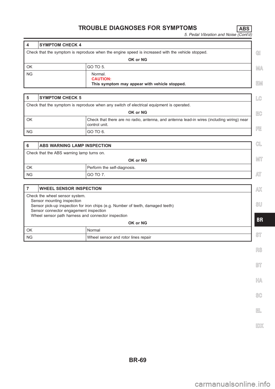
4 SYMPTOM CHECK 4
Check that the symptom is reproduce when the engine speed is increased withthe vehicle stopped.
OK or NG
OK GO TO 5.
NG Normal.
CAUTION:
This symptom may appear with vehicle stopped.
5 SYMPTOM CHECK 5
Check that the symptom is reproduce when any switch of electrical equipment is operated.
OK or NG
OK Check that there are no radio, antenna, and antenna lead-in wires (including wiring) near
control unit.
NG GO TO 6.
6 ABS WARNING LAMP INSPECTION
Check that the ABS warning lamp turns on.
OK or NG
OK Perform the self-diagnosis.
NG GO TO 7.
7 WHEEL SENSOR INSPECTION
Check the wheel sensor system.
Sensor mounting inspection
Sensor pick-up inspection for iron chips (e.g. Number of teeth, damaged teeth)
Sensor connector engagement inspection
Wheel sensor path harness and connector inspection
OK or NG
OK Normal
NG Wheel sensor and rotor lines repair
GI
MA
EM
LC
EC
FE
CL
MT
AT
AX
SU
ST
RS
BT
HA
SC
EL
IDX
TROUBLE DIAGNOSES FOR SYMPTOMSABS
5. Pedal Vibration and Noise (Cont’d)
BR-69
Page 2339 of 3189
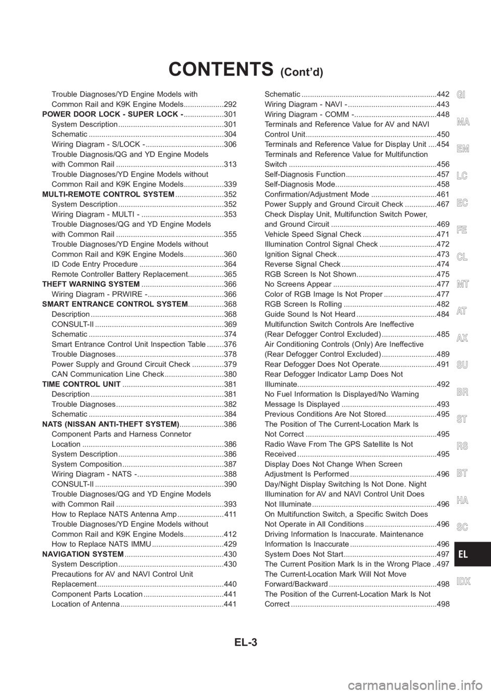
Trouble Diagnoses/YD Engine Models with
Common Rail and K9K Engine Models...................292
POWER DOOR LOCK - SUPER LOCK -...................301
System Description ..................................................301
Schematic <0011001100110011001100110011001100110011001100110011001100110011001100110011001100110011001100110011001100110011001100110011001100110011001100110011001100110011001100110011001100110011001100110011001100
11001100110011[..........304
Wiring Diagram - S/LOCK - .....................................306
Trouble Diagnosis/QG and YD Engine Models
with Common Rail ...................................................313
Trouble Diagnoses/YD Engine Models without
Common Rail and K9K Engine Models...................339
MULTI-REMOTE CONTROL SYSTEM.......................352
System Description ..................................................352
Wiring Diagram - MULTI - .......................................353
Trouble Diagnoses/QG and YD Engine Models
with Common Rail ...................................................355
Trouble Diagnoses/YD Engine Models without
Common Rail and K9K Engine Models...................360
ID Code Entry Procedure ........................................364
Remote Controller Battery Replacement.................365
THEFT WARNING SYSTEM.......................................366
Wiring Diagram - PRWIRE -....................................366
SMART ENTRANCE CONTROL SYSTEM.................368
Description <0011001100110011001100110011001100110011001100110011001100110011001100110011001100110011001100110011001100110011001100110011001100110011001100110011001100110011001100110011001100110011001100110011001100
110011[...........368
CONSULT-II <0011001100110011001100110011001100110011001100110011001100110011001100110011001100110011001100110011001100110011001100110011001100110011001100110011001100110011001100110011001100110011001100110011001100
1100110011[........369
Schematic <0011001100110011001100110011001100110011001100110011001100110011001100110011001100110011001100110011001100110011001100110011001100110011001100110011001100110011001100110011001100110011001100110011001100
11001100110011[..........374
Smart Entrance Control Unit Inspection Table ........376
Trouble Diagnoses...................................................378
Power Supply and Ground Circuit Check ...............379
CAN Communication Line Check ............................380
TIME CONTROL UNIT................................................381
Description <0011001100110011001100110011001100110011001100110011001100110011001100110011001100110011001100110011001100110011001100110011001100110011001100110011001100110011001100110011001100110011001100110011001100
110011[...........381
Trouble Diagnoses...................................................382
Schematic <0011001100110011001100110011001100110011001100110011001100110011001100110011001100110011001100110011001100110011001100110011001100110011001100110011001100110011001100110011001100110011001100110011001100
11001100110011[..........384
NATS (NISSAN ANTI-THEFT SYSTEM).....................386
Component Parts and Harness Connetor
Location <0011001100110011001100110011001100110011001100110011001100110011001100110011001100110011001100110011001100110011001100110011001100110011001100110011001100110011001100110011001100110011001100110011001100
110011001100110011[............386
System Description ..................................................386
System Composition ................................................387
Wiring Diagram - NATS -.........................................388
CONSULT-II <0011001100110011001100110011001100110011001100110011001100110011001100110011001100110011001100110011001100110011001100110011001100110011001100110011001100110011001100110011001100110011001100110011001100
1100110011[........390
Trouble Diagnoses/QG and YD Engine Models
with Common Rail ...................................................393
How to Replace NATS Antenna Amp ...................... 411
Trouble Diagnoses/YD Engine Models without
Common Rail and K9K Engine Models...................412
How to Replace NATS IMMU ..................................429
NAVIGATION SYSTEM...............................................430
System Description ..................................................430
Precautions for AV and NAVI Control Unit
Replacement <0011001100110011001100110011001100110011001100110011001100110011001100110011001100110011001100110011001100110011001100110011001100110011001100110011001100110011001100110011001100110011001100110011001100
110011[........440
Component Parts Location ......................................441
Location of Antenna .................................................441Schematic <0011001100110011001100110011001100110011001100110011001100110011001100110011001100110011001100110011001100110011001100110011001100110011001100110011001100110011001100110011001100110011001100110011001100
11001100110011[..........442
Wiring Diagram - NAVI - ..........................................443
Wiring Diagram - COMM -.......................................448
Terminals and Reference Value for AV and NAVI
Control Unit <0011001100110011001100110011001100110011001100110011001100110011001100110011001100110011001100110011001100110011001100110011001100110011001100110011001100110011001100110011001100110011001100110011001100
110011[..........450
Terminals and Reference Value for Display Unit ....454
Terminals and Reference Value for Multifunction
Switch <0011001100110011001100110011001100110011001100110011001100110011001100110011001100110011001100110011001100110011001100110011001100110011001100110011001100110011001100110011001100110011001100110011001100
11001100110011001100110011[.............456
Self-Diagnosis Function ...........................................457
Self-Diagnosis Mode................................................458
Confirmation/Adjustment Mode ...............................461
Power Supply and Ground Circuit Check ...............467
Check Display Unit, Multifunction Switch Power,
and Ground Circuit ..................................................469
Vehicle Speed Signal Check ...................................471
Illumination Control Signal Check ...........................472
Ignition Signal Check ...............................................473
Reverse Signal Check .............................................474
RGB Screen Is Not Shown......................................475
No Screens Appear .................................................477
Color of RGB Image Is Not Proper .........................477
RGB Screen Is Rolling ............................................482
Guide Sound Is Not Heard ......................................484
Multifunction Switch Controls Are Ineffective
(Rear Defogger Control Excluded) ..........................485
Air Conditioning Controls (Only) Are Ineffective
(Rear Defogger Control Excluded) ..........................489
Rear Defogger Does Not Operate...........................491
Rear Defogger Indicator Lamp Does Not
Illuminate<0011001100110011001100110011001100110011001100110011001100110011001100110011001100110011001100110011001100110011001100110011001100110011001100110011001100110011001100110011001100110011001100110011001100
1100110011[.............492
No Fuel Information Is Displayed/No Warning
Message Is Displayed .............................................493
Previous Conditions Are Not Stored........................495
The Position of The Current-Location Mark Is
Not Correct <0011001100110011001100110011001100110011001100110011001100110011001100110011001100110011001100110011001100110011001100110011001100110011001100110011001100110011001100110011001100110011001100110011001100
1100110011[.........495
Radio Wave From The GPS Satellite Is Not
Received <0011001100110011001100110011001100110011001100110011001100110011001100110011001100110011001100110011001100110011001100110011001100110011001100110011001100110011001100110011001100110011001100110011001100
110011001100110011[...........495
Display Does Not Change When Screen
Adjustment Is Performed .........................................496
Day/Night Display Switching Is Not Done. Night
Illumination for AV and NAVI Control Unit Does
Not Illuminate ...........................................................496
On Multifunction Switch, a Specific Switch Does
Not Operate in All Conditions ..................................496
Driving Information Is Inaccurate. Maintenance
Information Is Inaccurate .........................................496
System Does Not Start ............................................497
The Current Position Mark Is in the Wrong Place ..497
The Current-Location Mark Will Not Move
Forward/Backward ...................................................498
The Position of the Current-Location Mark Is Not
Correct <0011001100110011001100110011001100110011001100110011001100110011001100110011001100110011001100110011001100110011001100110011001100110011001100110011001100110011001100110011001100110011001100110011001100
1100110011001100110011[.............498
GI
MA
EM
LC
EC
FE
CL
MT
AT
AX
SU
BR
ST
RS
BT
HA
SC
IDX
CONTENTS(Cont’d)
EL-3
Page 2446 of 3189
Component Parts and Harness Connector
Location
NJEL0441For details, refer to “ELECTRICAL UNIT LOCATION” (EL-543) and
“HARNESS LAYOUT” (EL-550).
System DescriptionNJEL0442UNIFIED CONTROL METERNJEL0442S01Speedometer, odo/trip meter, tachometer, fuel gauge and water temperature gauge are controlled totally
by control unit built-in combination meter.
Digital meter is adopted for odo/trip meter.*
*The record of the odo meter is kept even if the battery cable is disconnected. The record of the trip meter
is erased when the battery cable is disconnected.
Odo/trip meter segment can be checked in diagnosis mode.
Meter/gauge can be checked in diagnosis mode.
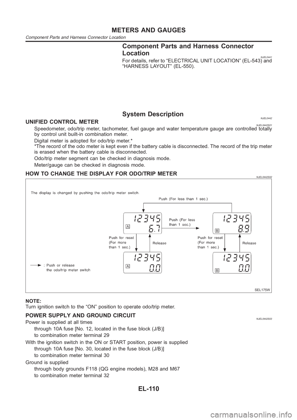
HOW TO CHANGE THE DISPLAY FOR ODO/TRIP METERNJEL0442S02
SEL175W
NOTE:
Turn ignition switch to the “ON” position to operate odo/trip meter.
POWER SUPPLY AND GROUND CIRCUITNJEL0442S03Power is supplied at all times
through 10A fuse [No. 12, located in the fuse block (J/B)]
to combination meter terminal 29
With the ignition switch in the ON or START position, power is supplied
through 10A fuse [No. 30, located in the fuse block (J/B)]
to combination meter terminal 30
Ground is supplied
through body grounds F118 (QG engine models), M28 and M67
to combination meter terminal 32
METERS AND GAUGES
Component Parts and Harness Connector Location
EL-110
Page 2447 of 3189
WATER TEMPERATURE GAUGE (QG AND YD ENGINE MODELS WITH COMMON RAIL)NJEL0442S09The water temperature gauge indicates the engine coolant temperature.
ECM provides a engine coolant temperature signal to combination meter forwater temperature gauge with
CAN communication line.
WATER TEMPERATURE GAUGE (YD ENGINE MODELS WITHOUT COMMON RAIL)NJEL0442S04The water temperature gauge indicates the engine coolant temperature. The reading on the gauge is based
on the resistance of the thermal transmitter.
As the temperature of the coolant increases, the resistance of the thermaltransmitter decreases. A variable
ground is supplied to terminal 35 of the combination meter for the water temperature gauge. The needle on
the gauge moves from “C” to “H”.
TACHOMETER (QG AND YD ENGINE MODELS WITH COMMON RAIL)NJEL0442S10The tachometer indicates engine speed in revolution per minutes (rpm). ECM provides an engine speed sig-
nal to combination meter for tachometer with CAN communication line.
TACHOMETER (YD ENGINE MODELS WITHOUT COMMON RAIL)NJEL0442S05The tachometer indicates engine speed in revolutions per minute (rpm).
The tachometer is regulated by a signal
from terminal 32 (Gasoline engine models) or 439 (Diesel engine models) ofthe ECM
to combination meter terminal 53 for the tachometer.
FUEL GAUGENJEL0442S06The fuel gauge indicates the approximate fuel level in the fuel tank.
The fuel gauge is regulated by a variable ground signal supplied
from body grounds F118 (QG engine models), M28 and M67
through terminals 33 and 32 of combination meter,
through terminal 1 of the fuel level sensor unit and
through terminal 4 of the fuel level sensor unit
to combination meter terminal 34 for the fuel gauge.
SPEEDOMETER (MODELS WITH ABS)NJEL0442S11The combination meter receives a signal from the ABS actuator and electricunit. The speedometer converts
the signal into the vehicle speed displayed.
SPEEDOMETER (MODELS WITHOUT ABS)NJEL0442S07The combination meter provides a voltage signal to the vehicle speed sensor for the speedometer.
The voltage is supplied
from combination meter terminal 13 for the speedometer
to terminal 1 of the vehicle speed sensor.
Ground is supplied
from body grounds F118 (QG engine models), M28 and M67
through terminals 32 and 14 of combination meter
to teminal 2 of the vehicle speed sensor.
The speedometer converts the voltage into the vehicle speed displayed.
GI
MA
EM
LC
EC
FE
CL
MT
AT
AX
SU
BR
ST
RS
BT
HA
SC
IDX
METERS AND GAUGES
System Description (Cont’d)
EL-111
Page 2453 of 3189
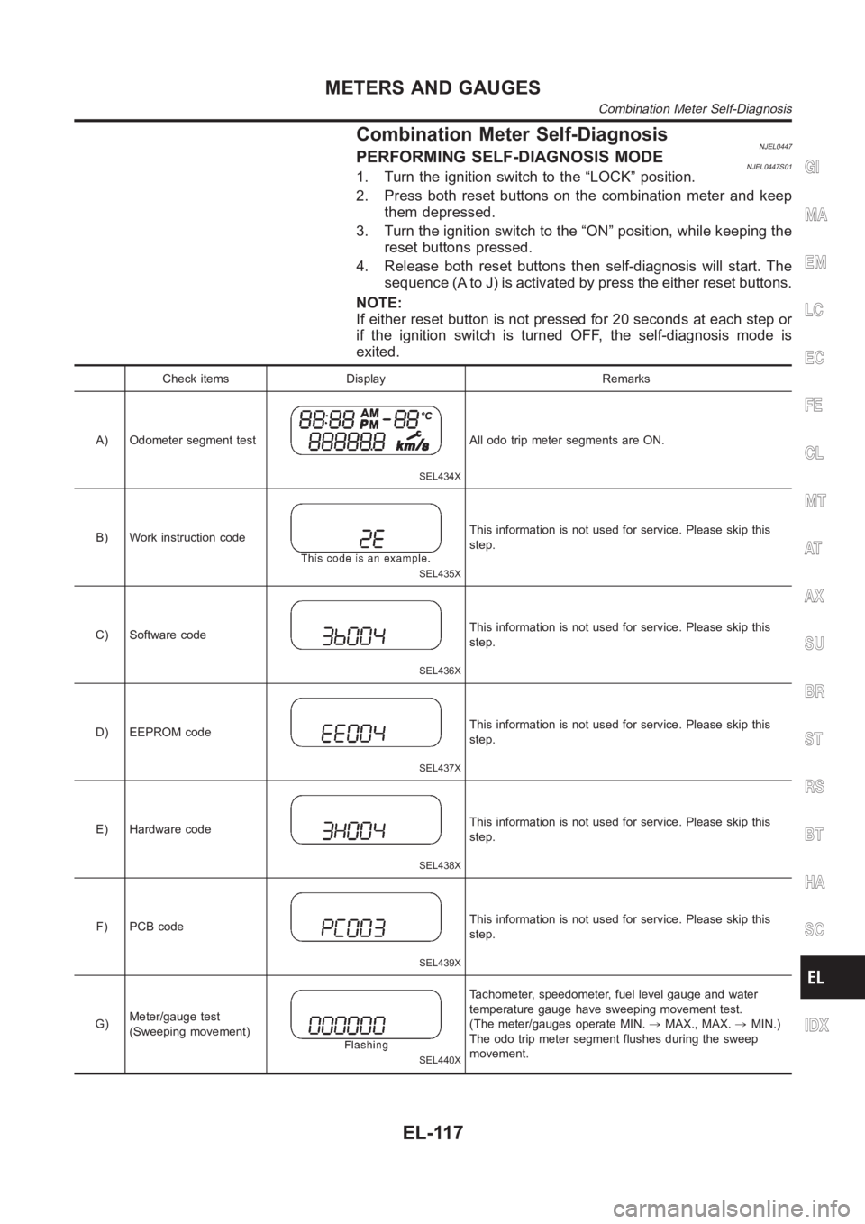
Combination Meter Self-DiagnosisNJEL0447PERFORMING SELF-DIAGNOSIS MODENJEL0447S011. Turn the ignition switch to the “LOCK” position.
2. Press both reset buttons on the combination meter and keep
them depressed.
3. Turn the ignition switch to the “ON” position, while keeping the
reset buttons pressed.
4. Release both reset buttons then self-diagnosis will start. The
sequence (A to J) is activated by press the either reset buttons.
NOTE:
If either reset button is not pressed for 20 seconds at each step or
if the ignition switch is turned OFF, the self-diagnosis mode is
exited.
Check items Display Remarks
A) Odometer segment test
SEL434X
All odo trip meter segments are ON.
B) Work instruction code
SEL435X
This information is not used for service. Please skip this
step.
C) Software code
SEL436X
This information is not used for service. Please skip this
step.
D) EEPROM code
SEL437X
This information is not used for service. Please skip this
step.
E) Hardware code
SEL438X
This information is not used for service. Please skip this
step.
F) PCB code
SEL439X
This information is not used for service. Please skip this
step.
G)Meter/gauge test
(Sweeping movement)
SEL440X
Tachometer, speedometer, fuel level gauge and water
temperature gauge have sweeping movement test.
(The meter/gauges operate MIN.,MAX., MAX.,MIN.)
The odo trip meter segment flushes during the sweep
movement.
GI
MA
EM
LC
EC
FE
CL
MT
AT
AX
SU
BR
ST
RS
BT
HA
SC
IDX
METERS AND GAUGES
Combination Meter Self-Diagnosis
EL-117
Page 2454 of 3189
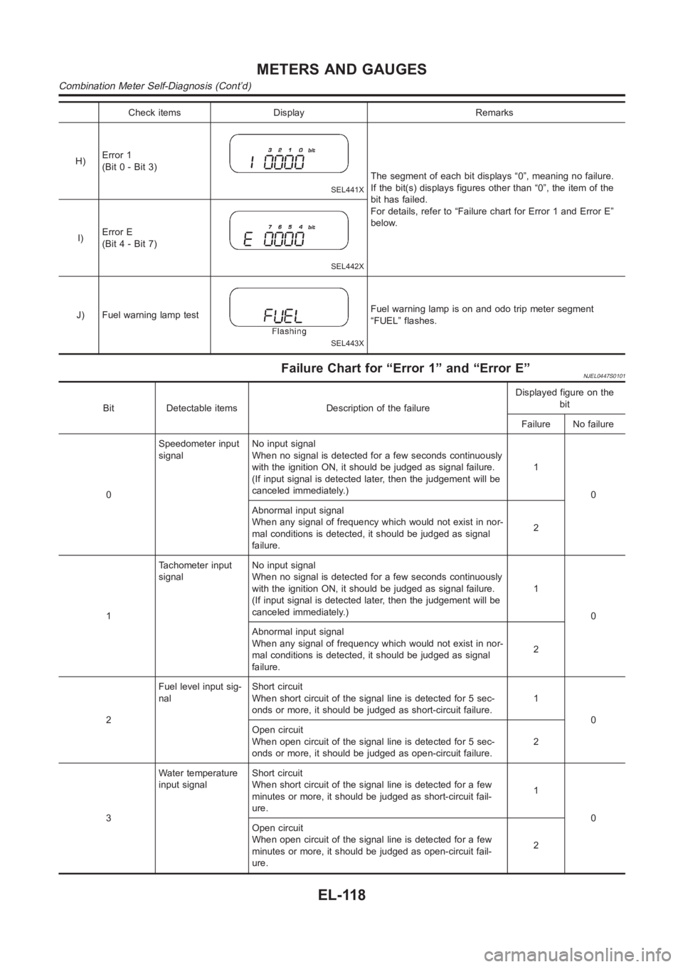
Check items Display Remarks
H)Error 1
(Bit 0 - Bit 3)
SEL441X
The segment of each bit displays “0”, meaning no failure.
If the bit(s) displays figures other than “0”, the item of the
bit has failed.
For details, refer to “Failure chart for Error 1 and Error E”
below.
I)Error E
(Bit 4 - Bit 7)
SEL442X
J) Fuel warning lamp test
SEL443X
Fuel warning lamp is on and odo trip meter segment
“FUEL” flashes.
Failure Chart for “Error 1” and “Error E”NJEL0447S0101
Bit Detectable items Description of the failureDisplayed figure on the
bit
Failure No failure
0Speedometer input
signalNo input signal
When no signal is detected for a few seconds continuously
with the ignition ON, it should be judged as signal failure.
(If input signal is detected later, then the judgement will be
canceled immediately.)1
0
Abnormal input signal
When any signal of frequency which would not exist in nor-
mal conditions is detected, it should be judged as signal
failure.2
1Tachometer input
signalNo input signal
When no signal is detected for a few seconds continuously
with the ignition ON, it should be judged as signal failure.
(If input signal is detected later, then the judgement will be
canceled immediately.)1
0
Abnormal input signal
When any signal of frequency which would not exist in nor-
mal conditions is detected, it should be judged as signal
failure.2
2Fuel level input sig-
nalShort circuit
When short circuit of the signal line is detected for 5 sec-
onds or more, it should be judged as short-circuit failure.1
0
Open circuit
When open circuit of the signal line is detected for 5 sec-
onds or more, it should be judged as open-circuit failure.2
3Water temperature
input signalShort circuit
When short circuit of the signal line is detected for a few
minutes or more, it should be judged as short-circuit fail-
ure.1
0
Open circuit
When open circuit of the signal line is detected for a few
minutes or more, it should be judged as open-circuit fail-
ure.2
METERS AND GAUGES
Combination Meter Self-Diagnosis (Cont’d)
EL-118