heater NISSAN ALMERA N16 2003 Electronic Manual PDF
[x] Cancel search | Manufacturer: NISSAN, Model Year: 2003, Model line: ALMERA N16, Model: NISSAN ALMERA N16 2003Pages: 3189, PDF Size: 54.76 MB
Page 972 of 3189

EC-642
[QG (WITHOUT EURO-OBD)]
HO2S2 HEATER
5. CHECK HEATED OXYGEN SENSOR 2 HEATER
Refer to EC-642, "
Component Inspection" .
OK or NG
OK >> GO TO 6.
NG >> Replace heated oxygen sensor 2.
6. CHECK INTERMITTENT INCIDENT
Refer to EC-485, "
TROUBLE DIAGNOSIS FOR INTERMITTENT INCIDENT" .
>>INSPECTION END
Component InspectionEBS00KKK
HEATED OXYGEN SENSOR 2 HEATER
1. Check resistance between HO2S2 terminals as follows.
2. If NG, replace heated oxygen sensor 2.
CAUTION:
●Discard any heated oxygen sensor which has been dropped
from a height of more than 0.5 m (19.7 in) onto a hard sur-
face such as a concrete floor; use a new one.
●Before installing new oxygen sensor, clean exhaust system
threads using Oxygen Sensor Thread Cleaner tool J-43897-
18 or J-43897-12 and approved anti-seize lubricant.
Removal and InstallationEBS00KKL
HEATED OXYGEN SENSOR 2
Refer to FE-10.
Terminal No. Resistance
1 and 4 2.3 - 4.3 Ω at 25°C (77°F)
2 and 1, 3, 4
∞Ω
(Continuity should not exist)
3 and 1, 2, 4
PBIB0542E
Page 981 of 3189

HO2S1
EC-651
[QG (WITHOUT EURO-OBD)]
C
D
E
F
G
H
I
J
K
L
MA
EC
8.CHECK HO2S1 GROUND CIRCUIT FOR OPEN AND SHORT
1. Turn ignition switch “OFF”.
2. Disconnect HO2S1 harness connector.
3. Disconnect ECM harness connector.
4. Check harness continuity between ECM terminal 74 and HO2S1
terminal 3. Refer to Wiring Diagram.
5. Also check harness for short to ground and short to power.
OK or NG
OK >> GO TO 9.
NG >> Repair open circuit or short to ground or short to power
in harness or connectors.
9.CHECK HO2S1 INPUT SIGNAL CIRCUIT FOR OPEN AND SHORT
1. Check harness continuity between ECM terminal 35 and HO2S1 terminal 2.
Refer to Wiring Diagram.
2. Check harness continuity between ECM terminal 35 or HO2S1 terminal 2 and ground.
Refer to Wiring Diagram.
3. Also check harness for short to power.
OK or NG
OK >> GO TO 10.
NG >> Repair open circuit or short to ground or short to power in harness or connectors.
10.CHECK HEATED OXYGEN SENSOR 1 HEATER
Refer to EC-637, "
Component Inspection" .
OK or NG
OK >> GO TO 11.
NG >> Replace malfunctioning heated oxygen sensor 1.
11 . CHECK MASS AIR FLOW SENSOR
Refer to EC-500, "
Component Inspection" .
OK or NG
OK >> GO TO 12.
NG >> Replace mass air flow sensor.
12.CHECK PCV VALVE
Refer to EC-720, "
Component Inspection" .
OK or NG
OK >> GO TO 13.
NG >> Replace PCV valve.
13.CHECK HEATED OXYGEN SENSOR 1
Refer to EC-652, "
Component Inspection" .
OK or NG
OK >> GO TO 14.
NG >> Replace malfunctioning heated oxygen sensor 1.Continuity should exist.
MBIB0091E
Continuity should exist.
Continuity should not exist.
Page 1052 of 3189

EC-722
[QG (WITHOUT EURO-OBD)]
SERVICE DATA AND SPECIFICATIONS (SDS)
SERVICE DATA AND SPECIFICATIONS (SDS)
PFP:00030
Fuel PressureEBS00KML
Idle Speed and Ignition TimingEBS00KMM
*1: Under the following conditions:
●Air conditioner switch: OFF
●Electric load: OFF (Lights, heater fan & rear window defogger)
●Steering wheel: Kept in straight-ahead position
Calculated Load ValueEBS00KMN
Mass Air Flow SensorEBS00KMO
*: Engine is warmed up to normal operating temperature and running under no-load.
Intake Air Temperature SensorEBS00KMP
Engine Coolant Temperature SensorEBS00KMQ
Heated Oxygen Sensor 1 HeaterEBS00KMR
Heated Oxygen sensor 2 HeaterEBS00KMS
Crankshaft Position Sensor (POS)EBS00KMT
Refer to EC-559, "Component Inspection" .
Camshaft Position Sensor (PHASE)EBS00KMU
Refer to EC-566, "Component Inspection" .
Fuel pressure at idle
Approximately 350 kPa (3.5bar, 3.57kg/cm2 , 51psi)
Target idle speed
No-load*1 (in “P” or N” position)A/T: 800±50 rpm
M/T: 700±50 rpm
Air conditioner: ON In “P” or N” position 900 rpm or more
Ignition timingIn “P” or N” position A/T: 10°±5° BTDC
M/T: 8°±5° BTDC
Calculated load value % (Using CONSULT-II)
At idle10 - 35
At 2,500 rpm10 - 35
Supply voltageBattery voltage (11 - 14V)
Output voltage at idle1.0 - 1.7*V
Mass air flow (Using CONSULT-II)1.0 - 4.0 g·m/sec at idle*
5.0 - 10.0 g·m/sec at 2,500 rpm*
Temperature °C (°F) Resistance kΩ
25 (77)1.9 - 2.1
80 (176)0.31 - 0.37
Temperature °C (°F) Resistance kΩ
20 (68) 2.1 - 2.9
50 (122) 0.68 - 1.00
90 (194) 0.236 - 0.260
Resistance [at 20°C (68°F)] 8 - 10Ω
Resistance [at 25°C (77°F)] 2.3 - 4.3Ω
Page 1079 of 3189
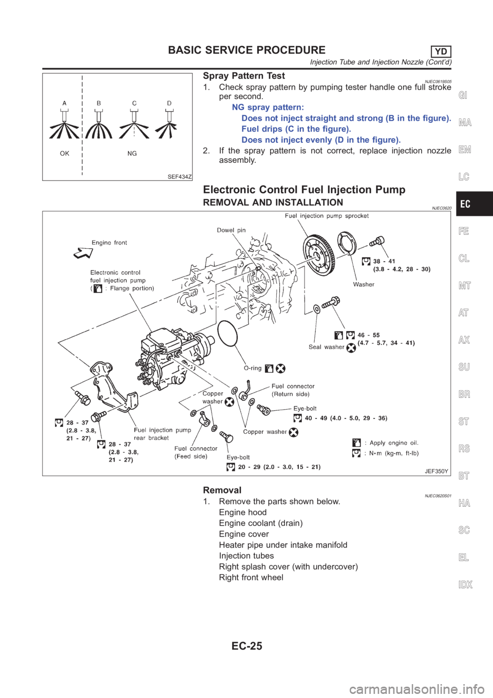
SEF434Z
Spray Pattern TestNJEC0619S051. Check spray pattern by pumping tester handle one full stroke
per second.
NG spray pattern:
Does not inject straight and strong (B in the figure).
Fuel drips (C in the figure).
Does not inject evenly (D in the figure).
2. If the spray pattern is not correct, replace injection nozzle
assembly.
Electronic Control Fuel Injection Pump
REMOVAL AND INSTALLATIONNJEC0620
JEF350Y
RemovalNJEC0620S011. Remove the parts shown below.
Engine hood
Engine coolant (drain)
Engine cover
Heater pipe under intake manifold
Injection tubes
Right splash cover (with undercover)
Right front wheel
GI
MA
EM
LC
FE
CL
MT
AT
AX
SU
BR
ST
RS
BT
HA
SC
EL
IDX
BASIC SERVICE PROCEDUREYD
Injection Tube and Injection Nozzle (Cont’d)
EC-25
Page 1565 of 3189

CAN COMMUNICATION
AT-109
[EURO-OBD]
D
E
F
G
H
I
J
K
L
MA
B
AT
CAN COMMUNICATIONPFP:23710
System DescriptionECS007O2
CAN (Controller Area Network) is a serial communication line for real time application. It is an on-vehicle mul-
tiplex communication line with high data communication speed and excellent error detection ability. Many elec-
tronic control units are equipped onto a vehicle, and each control unit shares information and links with other
control units during operation (not independent). In CAN communication, control units are connected with 2
communication lines (CAN H line, CAN L line) allowing a high rate of information transmission with less wiring.
Each control unit transmits/receives data but selectively reads required data only.
CAN Communication UnitECS007O3
×:Applicable
TYPE1
System diagram
Input/output signal chart
T: Transmit R: Receive Body type Sedan/ 5DH/B/ 3DH/B
Axle2WD
Engine QG18DE QG15DE/QG18DE
Transmission A/T M/T
Brake controlABS
CAN communication unit
ECM××
TCM×
Smart entrance control unit××
Data link connector××
Combination meter××
CAN communication type AT-109, "
TYPE1"AT-110, "TYPE 2"
SEL825Y
Signals ECM TCMSmart entrance
control unitCombination meter
Engine speed signal T R
Brake switch signal R T
Rear window defogger signal R T
Heater fan switch signal R T
Air conditioner switch signal R T
MI signal T R
Current gear position signal T R
Engine coolant temperature signal T R
Fuel consumption signal T R
Page 1566 of 3189

AT-110
[EURO-OBD]
CAN COMMUNICATION
TYPE 2
System diagram
Input/output signal chart
T: Transmit R: Receive Vehicle speed signal R T
Seat belt reminder signalRT
Headlamp switch signalTR
Flashing indicator signalTR
Engine cooling fan speed signal T R
Child lock indicator signalTR
Door switches state signalTR
A/C compressor signal T R
Accelerator pedal position signal T R
Output shaft revolution signal R T
OD OFF switch signal R T
OD OFF indicator signal T R
A/T self-diagnosis signal R TSignals ECM TCMSmart entrance
control unitCombination meter
SEL826Y
Signals ECMSmart entrance control
unitCombination meter
Engine speed signal T R
Rear window defogger signal R T
Heater fan switch signal R T
Air conditioner switch signal R T
MI signal T R
Engine coolant temperature signal T R
Fuel consumption signal T R
Vehicle speed signal R T
Seat belt reminder signal R T
Headlamp switch signal T R
Flashing indicator signal T R
Engine cooling fan speed signal T R
Child lock indicator signal T R
Door switches state signal T R
A/C compressor signal T R
Page 1761 of 3189

CAN COMMUNICATION
AT-305
[EXC.F/EURO-OBD]
D
E
F
G
H
I
J
K
L
MA
B
AT
CAN COMMUNICATIONPFP:23710
System DescriptionECS007QX
CAN (Controller Area Network) is a serial communication line for real time application. It is an on-vehicle mul-
tiplex communication line with high data communication speed and excellent error detection ability. Many elec-
tronic control units are equipped onto a vehicle, and each control unit shares information and links with other
control units during operation (not independent). In CAN communication, control units are connected with 2
communication lines (CAN H line, CAN L line) allowing a high rate of information transmission with less wiring.
Each control unit transmits/receives data but selectively reads required data only.
CAN Communication UnitECS007QY
×:Applicable
TYPE 1
System diagram
Input/output signal chart
T: Transmit R: Receive Body type Sedan/ 5DH/B/ 3DH/B
Axle2WD
Engine QG18DE QG15DE/QG18DE
Transmission A/T M/T
Brake controlABS
CAN communication unit
ECM××
TCM×
Smart entrance control unit××
Data link connector××
Combination meter××
CAN communication type AT-305, "
TYPE 1"AT- 3 0 6 , "TYPE 2"
SEL825Y
Signals ECM TCMSmart entrance
control unitCombination meter
Engine speed signal T R
Brake switch signal R T
Rear window defogger signal R T
Heater fan switch signal R T
Air conditioner switch signal R T
MI signal T R
Current gear position signal T R
Engine coolant temperature signal T R
Fuel consumption signal T R
Page 1762 of 3189

AT-306
[EXC.F/EURO-OBD]
CAN COMMUNICATION
TYPE 2
System diagram
Input/output signal chart
T: Transmit R: Receive Vehicle speed signal R T
Seat belt reminder signalRT
Headlamp switch signalTR
Flashing indicator signalTR
Engine cooling fan speed signal T R
Child lock indicator signalTR
Door switches state signalTR
A/C compressor signal T R
Accelerator pedal position signal T R
Output shaft revolution signal R T
OD OFF switch signal R T
OD OFF indicator signal T R
A/T self-diagnosis signal R TSignals ECM TCMSmart entrance
control unitCombination meter
SEL826Y
Signals ECMSmart entrance control
unitCombination meter
Engine speed signal T R
Rear window defogger signal R T
Heater fan switch signal R T
Air conditioner switch signal R T
MI signal T R
Engine coolant temperature signal T R
Fuel consumption signal T R
Vehicle speed signal R T
Seat belt reminder signal R T
Headlamp switch signal T R
Flashing indicator signal T R
Engine cooling fan speed signal T R
Child lock indicator signal T R
Door switches state signal T R
A/C compressor signal T R
Page 1983 of 3189
ATC-3
C
D
E
F
G
H
I
K
L
MA
B
AT C SUNLOAD SENSOR ...............................................117
Removal and Installation ....................................... 117
INTAKE SENSOR CIRCUIT ....................................118
Removal and Installation ....................................... 118
BLOWER UNIT ........................................................119
Removal and Installation ....................................... 119
REMOVAL .......................................................... 119
INSTALLATION .................................................. 119
Disassembly and Assembly .................................. 119
BLOWER MOTOR .................................................. 120
Removal and Installation ...................................... 120
INTAKE DOOR MOTOR ......................................... 121
Removal and Installation ...................................... 121
HEATER & COOLING UNIT ASSEMBLY .............. 122
Removal and Installation ...................................... 122
REMOVAL ......................................................... 122
INSTALLATION ................................................. 123
Disassembly and Assembly ................................. 123
MODE DOOR MOTOR ........................................... 125
Removal and Installation ...................................... 125
AIR MIX DOOR MOTOR ......................................... 126
Removal and Installation ...................................... 126
FAN CONTROL AMPLIFIER .................................. 127
Removal and Installation ...................................... 127
VENTILATION AIR FILTER .................................... 128
Removal and Installation ...................................... 128
FUNCTION ........................................................ 128
REPLACEMENT TIMING .................................. 128
REPLACEMENT AND PROCEDURES ............ 128
HEATER CORE ...................................................... 129
Removal and Installation ...................................... 129
DUCTS AND GRILLES .......................................... 130
Removal and Installation ...................................... 130
VENTILATOR DUCT, DEFROSTER NOZZLE
AND DEFROSTER DUCTS .............................. 130
CENTER VENTILATOR GRILLE ...................... 130
SIDE VENTILATOR GRILLE ............................. 130
FOOT DUCT ..................................................... 130
FLOOR DUCT ................................................... 131
REFRIGERANT LINES ........................................... 132
HFC-134a (R-134a) Service Procedure ............... 132
SETTING OF SERVICE TOOLS AND EQUIP-
MENT ................................................................ 132Components .........................................................134
Compressor ..........................................................136
REMOVAL .........................................................136
INSTALLATION .................................................137
Compressor Clutch .............................................. .138
REMOVAL .........................................................138
INSTALLATION .................................................139
Low-pressure Flexible Hose .................................141
REMOVAL .........................................................141
INSTALLATION .................................................141
High-pressure Flexible Hose ................................141
REMOVAL .........................................................141
INSTALLATION .................................................142
High-pressure Pipe ...............................................142
REMOVAL .........................................................142
INSTALLATION .................................................142
Refrigerant Pressure Sensor ................................142
REMOVAL AND INSTALLATION ......................142
Dual-pressure Switch ...........................................143
REMOVAL AND INSTALLATION ......................143
Condenser Assembly ...........................................143
REMOVAL .........................................................143
INSTALLATION .................................................143
Evaporator ............................................................144
REMOVAL .........................................................144
INSTALLATION .................................................144
Expansion Valve ...................................................144
REMOVAL .........................................................144
INSTALLATION .................................................144
Checking for Refrigerant Leaks ............................145
Checking System for Leaks Using the Fluorescent
Leak Detector .......................................................145
Dye Injection .........................................................146
Electronic Refrigerant Leak Detector ....................146
PRECAUTIONS FOR HANDLING LEAK
DETECTOR .......................................................146
CHECKING PROCEDURE ...............................147
SERVICE DATA AND SPECIFICATIONS (SDS) ....149
Compressor ..........................................................149
Lubricant ...............................................................149
Refrigerant ............................................................149
Engine Idling Speed .............................................149
Belt Tension ..........................................................149
Page 2042 of 3189

ATC-62
TROUBLE DIAGNOSIS
COMPONENT DESCRIPTION
Mode Door Motor
The mode door motor is attached to the heater & cooling unit. It
rotates so that air is discharged from the outlet set by the auto ampli-
fier. Motor rotation is conveyed to a link which activates the mode
door.
DIAGNOSTIC PROCEDURE FOR MODE DOOR
SYMPTOM: Mode door motor does not operate normally.
Perform diagnostic procedure for LAN system circuit. Refer to AT C - 5 7 , "
LAN System Circuit" .
RJIA0774E
RJIA0775E