heater NISSAN ALMERA N16 2003 Electronic Manual PDF
[x] Cancel search | Manufacturer: NISSAN, Model Year: 2003, Model line: ALMERA N16, Model: NISSAN ALMERA N16 2003Pages: 3189, PDF Size: 54.76 MB
Page 2045 of 3189

TROUBLE DIAGNOSIS
ATC-65
C
D
E
F
G
H
I
K
L
MA
B
AT C
COMPONENT DESCRIPTION
Air Mix Door Motor
The air mix door motor is attached to the heater & cooling unit. It
rotates so that the air mix door is opened or closed to a position set
by the auto amplifier. The air mix door position is then fed back to the
auto amplifier by PBR built-in air mix door motor.
DIAGNOSTIC PROCEDURE FOR AIR MIX DOOR MOTOR
SYMPTOM: Discharge air temperature does not change.
Perform diagnostic procedure for LAN system circuit. Refer to ATC-57, "
LAN System Circuit" .
RJIA0774E
RJIA0775E
Page 2051 of 3189
TROUBLE DIAGNOSIS
ATC-71
C
D
E
F
G
H
I
K
L
MA
B
AT C
In the most extreme case (very low ambient) the blower starting delay will be 150 seconds as described
above. After this delay, the blower will operate at low speed until the engine coolant temperature rises above
56°C (133°F), at which time the blower speed will increase to the objective speed.
Start Up From Usual or HOT SOAK Condition (Automatic mode)
The blower will begin operation momentarily after the A/C button is pushed. The blower speed will gradually
rise to the objective speed over a time period of 3 seconds or less (actual time depends on the objective
blower speed).
Blower Speed Compensation
Sunload
When the in-vehicle temperature and the set temperature are very close, the blower will be operating at low
speed. The low speed will vary depending on the sunload. During conditions of low or no sunload, the blower
low speed is usual low speed (approx. 4V). During high sunload conditions, the auto amp causes the blower
fan speed to increase.(Approx. 7V)
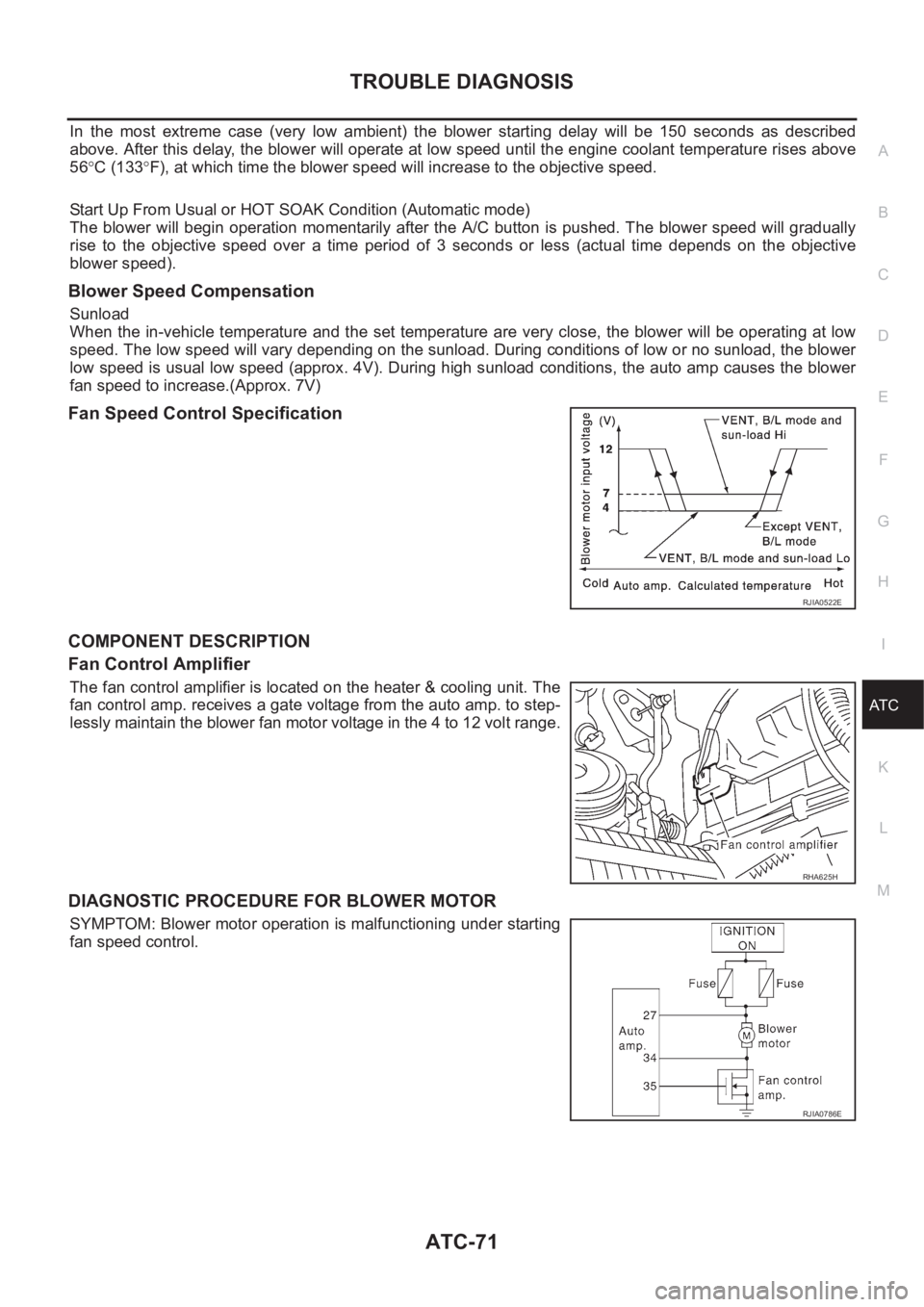
Fan Speed Control Specification
COMPONENT DESCRIPTION
Fan Control Amplifier
The fan control amplifier is located on the heater & cooling unit. The
fan control amp. receives a gate voltage from the auto amp. to step-
lessly maintain the blower fan motor voltage in the 4 to 12 volt range.
DIAGNOSTIC PROCEDURE FOR BLOWER MOTOR
SYMPTOM: Blower motor operation is malfunctioning under starting
fan speed control.
RJIA0522E
RHA625H
RJIA0786E
Page 2082 of 3189

ATC-102
TROUBLE DIAGNOSIS
COMPONENT INSPECTION
Ambient Sensor
After disconnecting ambient sensor harness connector, measure
resistance between terminals 2 and 1 at sensor harness side, using
the table below.
If NG, replace ambient sensor.
In-vehicle Sensor CircuitEJS001ZW
COMPONENT DESCRIPTION
In-vehicle sensor
The in-vehicle sensor is located on instrument lower panel. It con-
verts variations in temperature of compartment air drawn from the
aspirator into a resistance value. It is then input into the auto ampli-
fier.
Aspirator
The aspirator is located on heater & cooling unit. It produces vacuum
pressure due to air discharged from the heater & cooling unit, contin-
uously taking compartment air in the aspirator.
Temperature °C (°F) Resistance kΩ
−15 (5) 12.73
−10 (14) 9.92
−5 (23) 7.80
0 (32) 6.19
5 (41) 4.95
10 (50) 3.99
15 (59) 3.24
20 (68) 2.65
25 (77) 2.19
30 (86) 1.81
35 (95) 1.51
40 (104) 1.27
45 (113) 1.07
RJIA1713E
RJIA1714E
RHA650H
Page 2088 of 3189

ATC-108
TROUBLE DIAGNOSIS
Intake Sensor Circuit
EJS001ZY
COMPONENT DESCRIPTION
Intake Sensor
The intake sensor is located on the heater & cooling unit. It converts
temperature of air after it passes through the evaporator into a resis-
tance value which is then input to the auto amp.
After disconnecting intake sensor harness connector, measure resis-
tance between terminals 1 and 2 at sensor harness side, using the
table below.
If NG, replace intake sensor.
DIAGNOSTIC PROCEDURE FOR INTAKE SENSOR
SYMPTOM: Intake sensor circuit is open or shorted. (24 or −24) is
indicated on auto amp. as a result of conducting Self-diagnosis
STEP 2.
1. CHECK INTAKE SENSOR CIRCUIT BETWEEN INTAKE SENSOR AND GROUND
Disconnect intake sensor harness connector.
OK or NG
OK >> GO TO 2.
NG >> GO TO 4.
Temperature °C (°F) Resistance kΩ
−15 (5) 12.34
−10 (14) 9.62
−5 (23) 7.56
0 (32) 6.00
5 (41) 4.80
10 (50) 3.87
15 (59) 3.15
20 (68) 2.57
25 (77) 2.12
30 (86) 1.76
35 (95) 1.47
40 (104) 1.23
45 (113) 1.04
RJIA0166E
RHA056GA
Terminal
Voltag e (+)
(-)
Intake sensor
connectorTerminal No.
(Wire color)
M197 1 (OR/B) Ground Approx. 5V
RJIA0819E
Page 2102 of 3189
ATC-122
HEATER & COOLING UNIT ASSEMBLY
HEATER & COOLING UNIT ASSEMBLY
PFP:27110
Removal and InstallationEJS0020A
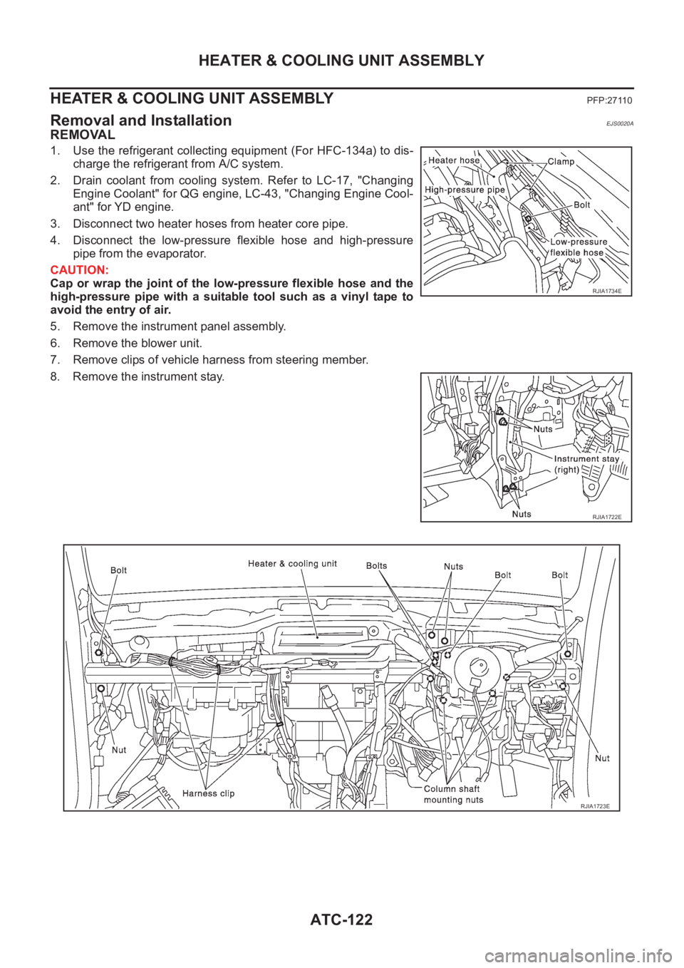
REMOVAL
1. Use the refrigerant collecting equipment (For HFC-134a) to dis-
charge the refrigerant from A/C system.
2. Drain coolant from cooling system. Refer to LC-17, "Changing
Engine Coolant" for QG engine, LC-43, "Changing Engine Cool-
ant" for YD engine.
3. Disconnect two heater hoses from heater core pipe.
4. Disconnect the low-pressure flexible hose and high-pressure
pipe from the evaporator.
CAUTION:
Cap or wrap the joint of the low-pressure flexible hose and the
high-pressure pipe with a suitable tool such as a vinyl tape to
avoid the entry of air.
5. Remove the instrument panel assembly.
6. Remove the blower unit.
7. Remove clips of vehicle harness from steering member.
8. Remove the instrument stay.
RJIA1734E
RJIA1722E
RJIA1723E
Page 2103 of 3189
HEATER & COOLING UNIT ASSEMBLY
ATC-123
C
D
E
F
G
H
I
K
L
MA
B
AT C
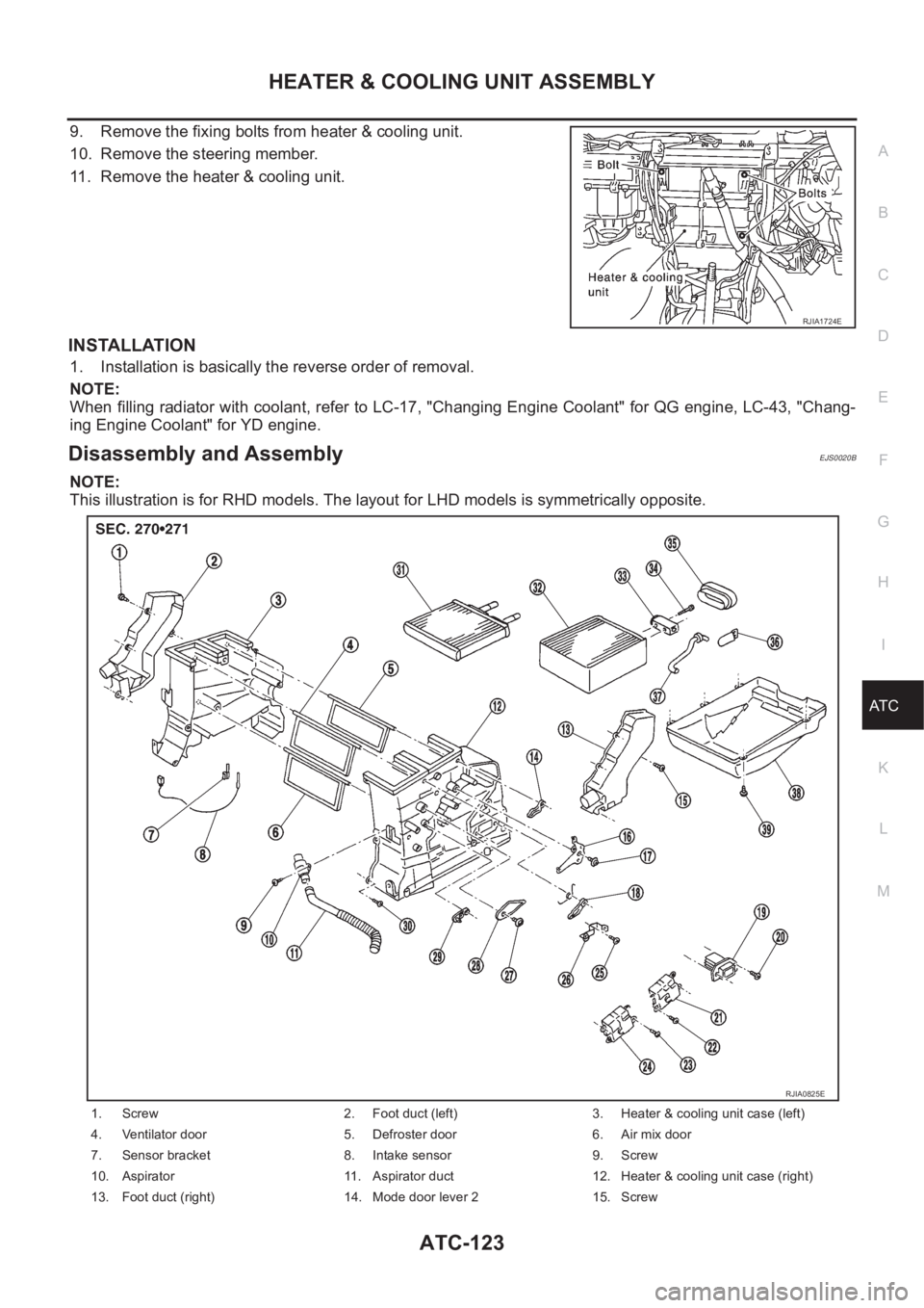
9. Remove the fixing bolts from heater & cooling unit.
10. Remove the steering member.
11. Remove the heater & cooling unit.
INSTALLATION
1. Installation is basically the reverse order of removal.
NOTE:
When filling radiator with coolant, refer to LC-17, "Changing Engine Coolant" for QG engine, LC-43, "Chang-
ing Engine Coolant" for YD engine.
Disassembly and AssemblyEJS0020B
NOTE:
This illustration is for RHD models. The layout for LHD models is symmetrically opposite.
RJIA1724E
1. Screw 2. Foot duct (left) 3. Heater & cooling unit case (left)
4. Ventilator door 5. Defroster door 6. Air mix door
7. Sensor bracket 8. Intake sensor 9. Screw
10. Aspirator 11. Aspirator duct 12. Heater & cooling unit case (right)
13. Foot duct (right) 14. Mode door lever 2 15. Screw
RJIA0825E
Page 2104 of 3189
ATC-124
HEATER & COOLING UNIT ASSEMBLY
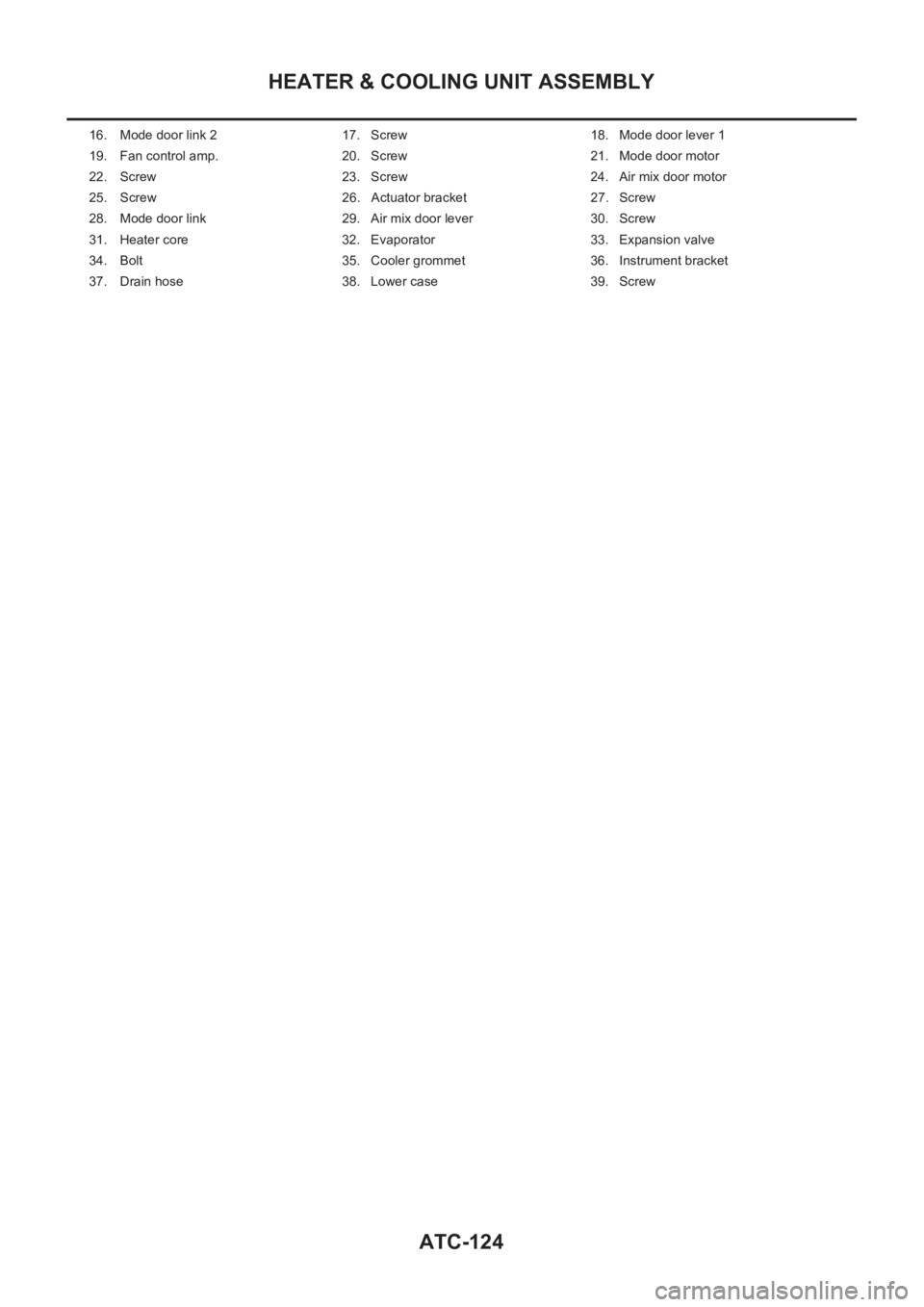
16. Mode door link 2 17. Screw 18. Mode door lever 1
19. Fan control amp. 20. Screw 21. Mode door motor
22. Screw 23. Screw 24. Air mix door motor
25. Screw 26. Actuator bracket 27. Screw
28. Mode door link 29. Air mix door lever 30. Screw
31. Heater core 32. Evaporator 33. Expansion valve
34. Bolt 35. Cooler grommet 36. Instrument bracket
37. Drain hose 38. Lower case 39. Screw
Page 2109 of 3189

HEATER CORE
ATC-129
C
D
E
F
G
H
I
K
L
MA
B
AT C
HEATER COREPFP:27140
Removal and InstallationEJS0020G
1. Remove the heater & cooling unit. Refer to ATC-122, "Removal and Installation" .
2. Separate the heater & cooling unit, then remove the heater core. Refer to ATC-123, "
Disassembly and
Assembly" .
Page 2110 of 3189

ATC-130
DUCTS AND GRILLES
DUCTS AND GRILLES
PFP:27860
Removal and InstallationEJS0020H
VENTILATOR DUCT, DEFROSTER NOZZLE AND DEFROSTER DUCTS
NOTE:
This illustration is for RHD models. The layout for LHD models is symmetrically opposite.
CENTER VENTILATOR GRILLE
1. Remove the cluster lid C. Refer to BT-25, "INSTRUMENT PANEL ASSEMBLY".
2. Remove the center ventilator grille.
SIDE VENTILATOR GRILLE
1. Remove the instrument panel.
2. Remove the side ventilator grille.
FOOT DUCT
1. Remove the heater & cooling unit. Refer to ATC-122, "Removal
and Installation" .
2. Remove the foot duct.
1. Defroster nozzle 2. Side defroster duct (right) 3. Instrument panel
4. Side ventilator grille (right) 5. Cluster lid C (center ventilator grille) 6. Side ventilator grille (left)
7. Ventilator duct 8. Side defroster duct (left)
RJIA1726E
RJIA1727E
RJIA0830E
Page 2124 of 3189

ATC-144
REFRIGERANT LINES
Evaporator
EJS0020S
REMOVAL
1. Use refrigerant collecting equipment (for HFC-134a) to dis-
charge refrigerant.
2. Disconnect the low-pressure flexible hose and the high-pressure
pipe from the evaporator.
CAUTION:
Cap or wrap the joint of the low-pressure flexible hose and
the high-pressure pipe with a suitable tool such as a vinyl
tape to avoid the entry of air.
3. Hold expansion valve and move it slightly upward. Push evapo-
rator toward rear of vehicle.
4. Remove the drain hose and lower cover mounting screw.
5. Swivel rear of lower case toward passenger seat to remove
lower case.
6. Remove the intake sensor from evaporator.
7. Slide the evaporator to backward, then remove it from the heater
& cooling unit.
INSTALLATION
CAUTION:
●Replace the O-rings of the low-pressure flexible hose and the high-pressure pipe with new ones,
then apply compressor oil to them when installing them.
●Mark the mounting position of the intake sensor bracket.
Expansion ValveEJS0020T
REMOVAL
1. Use refrigerant collecting equipment (for HFC-134a) to dis-
charge refrigerant.
2. Disconnect the low-pressure flexible hose and high-pressure
pipe from the evaporator.
CAUTION:
Cap or wrap the joint of the low-pressure flexible hose and
the high-pressure pipe with a suitable tool such as a vinyl
tape to avoid the entry of air.
3. Remove the evaporator. Refer to ATC-144, "
REMOVAL" .
4. Remove the expansion valve from evaporator.
INSTALLATION
1. Set the expansion valve to cooler grommet.
RJIA1720E
RJIA0189E
RJIA1720E
RJIA0840E