cooling fan NISSAN ALMERA N16 2003 Electronic Manual Online
[x] Cancel search | Manufacturer: NISSAN, Model Year: 2003, Model line: ALMERA N16, Model: NISSAN ALMERA N16 2003Pages: 3189, PDF Size: 54.76 MB
Page 2846 of 3189
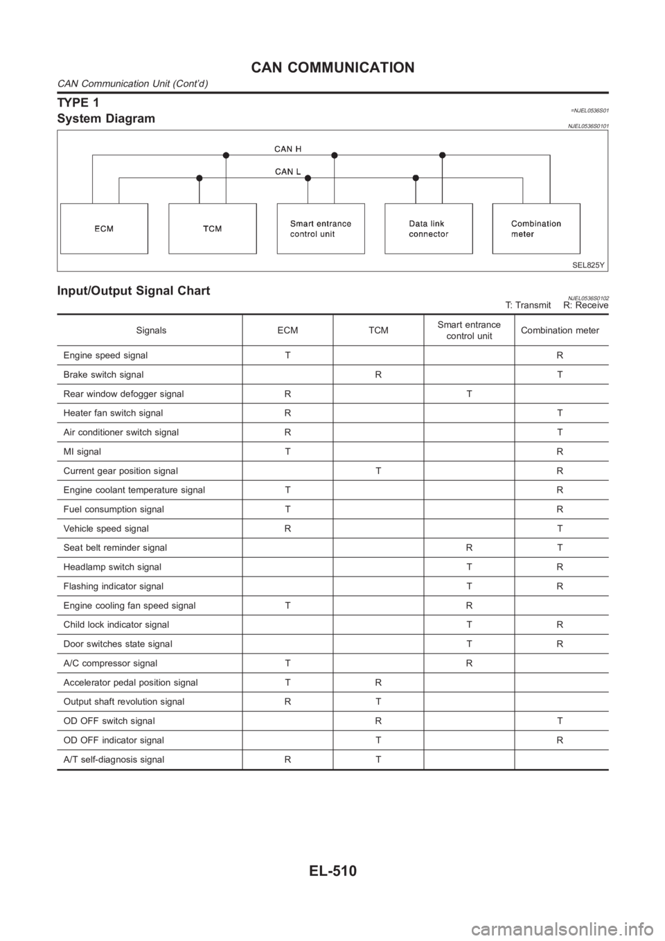
TYPE 1=NJEL0536S01System DiagramNJEL0536S0101
SEL825Y
Input/Output Signal ChartNJEL0536S0102T: Transmit R: Receive
Signals ECM TCMSmart entrance
control unitCombination meter
Engine speed signal T R
Brake switch signal R T
Rear window defogger signal R T
Heater fan switch signal R T
Air conditioner switch signal R T
MI signal T R
Current gear position signal T R
Engine coolant temperature signal T R
Fuel consumption signal T R
Vehicle speed signal R T
Seat belt reminder signalRT
Headlamp switch signalTR
Flashing indicator signalTR
Engine cooling fan speed signal T R
Child lock indicator signalTR
Door switches state signal T R
A/C compressor signal T R
Accelerator pedal position signal T R
Output shaft revolution signal R T
OD OFF switch signal R T
OD OFF indicator signal T R
A/T self-diagnosis signal R T
CAN COMMUNICATION
CAN Communication Unit (Cont’d)
EL-510
Page 2847 of 3189
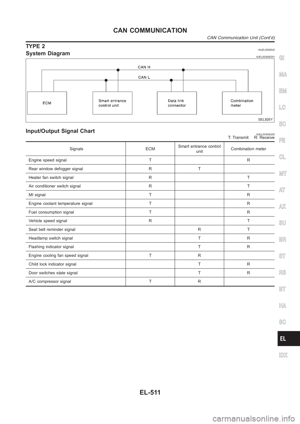
TYPE 2=NJEL0536S02System DiagramNJEL0536S0201
SEL826Y
Input/Output Signal ChartNJEL0536S0202T: Transmit R: Receive
Signals ECMSmart entrance control
unitCombination meter
Engine speed signal T R
Rear window defogger signal R T
Heater fan switch signal R T
Air conditioner switch signal R T
MI signal T R
Engine coolant temperature signal T R
Fuel consumption signal T R
Vehicle speed signal R T
Seat belt reminder signal R T
Headlamp switch signal T R
Flashing indicator signal T R
Engine cooling fan speed signal T R
Child lock indicator signal T R
Door switches state signal T R
A/C compressor signal T R
GI
MA
EM
LC
EC
FE
CL
MT
AT
AX
SU
BR
ST
RS
BT
HA
SC
IDX
CAN COMMUNICATION
CAN Communication Unit (Cont’d)
EL-511
Page 2935 of 3189
NJEL0311
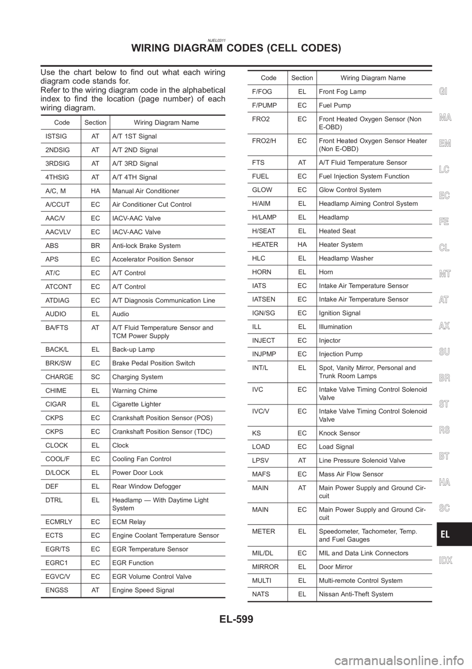
Use the chart below to find out what each wiring
diagram code stands for.
Refer to the wiring diagram code in the alphabetical
index to find the location (page number) of each
wiring diagram.
Code Section Wiring Diagram Name
ISTSIG AT A/T 1ST Signal
2NDSIG AT A/T 2ND Signal
3RDSIG AT A/T 3RD Signal
4THSIG AT A/T 4TH Signal
A/C, M HA Manual Air Conditioner
A/CCUT EC Air Conditioner Cut Control
AAC/V EC IACV-AAC Valve
AACVLV EC IACV-AAC Valve
ABS BR Anti-lock Brake System
APS EC Accelerator Position Sensor
AT/C EC A/T Control
ATCONT EC A/T Control
ATDIAG EC A/T Diagnosis Communication Line
AUDIO EL Audio
BA/FTS AT A/T Fluid Temperature Sensor and
TCM Power Supply
BACK/L EL Back-up Lamp
BRK/SW EC Brake Pedal Position Switch
CHARGE SC Charging System
CHIME EL Warning Chime
CIGAR EL Cigarette Lighter
CKPS EC Crankshaft Position Sensor (POS)
CKPS EC Crankshaft Position Sensor (TDC)
CLOCK EL Clock
COOL/F EC Cooling Fan Control
D/LOCK EL Power Door Lock
DEF EL Rear Window Defogger
DTRL EL Headlamp — With Daytime Light
System
ECMRLY EC ECM Relay
ECTS EC Engine Coolant Temperature Sensor
EGR/TS EC EGR Temperature Sensor
EGRC1 EC EGR Function
EGVC/V EC EGR Volume Control Valve
ENGSS AT Engine Speed Signal
Code Section Wiring Diagram Name
F/FOG EL Front Fog Lamp
F/PUMP EC Fuel Pump
FRO2 EC Front Heated Oxygen Sensor (Non
E-OBD)
FRO2/H EC Front Heated Oxygen Sensor Heater
(Non E-OBD)
FTS AT A/T Fluid Temperature Sensor
FUEL EC Fuel Injection System Function
GLOW EC Glow Control System
H/AIM EL Headlamp Aiming Control System
H/LAMP EL Headlamp
H/SEAT EL Heated Seat
HEATER HA Heater System
HLC EL Headlamp Washer
HORN EL Horn
IATS EC Intake Air Temperature Sensor
IATSEN EC Intake Air Temperature Sensor
IGN/SG EC Ignition Signal
ILL EL Illumination
INJECT EC Injector
INJPMP EC Injection Pump
INT/L EL Spot, Vanity Mirror, Personal and
Trunk Room Lamps
IVC EC Intake Valve Timing Control Solenoid
Valve
IVC/V EC Intake Valve Timing Control Solenoid
Valve
KS EC Knock Sensor
LOAD EC Load Signal
LPSV AT Line Pressure Solenoid Valve
MAFS EC Mass Air Flow Sensor
MAIN AT Main Power Supply and Ground Cir-
cuit
MAIN EC Main Power Supply and Ground Cir-
cuit
METER EL Speedometer, Tachometer, Temp.
and Fuel Gauges
MIL/DL EC MIL and Data Link Connectors
MIRROR EL Door Mirror
MULTI EL Multi-remote Control System
NATS EL Nissan Anti-Theft System
GI
MA
EM
LC
EC
FE
CL
MT
AT
AX
SU
BR
ST
RS
BT
HA
SC
IDX
WIRING DIAGRAM CODES (CELL CODES)
EL-599
Page 2954 of 3189
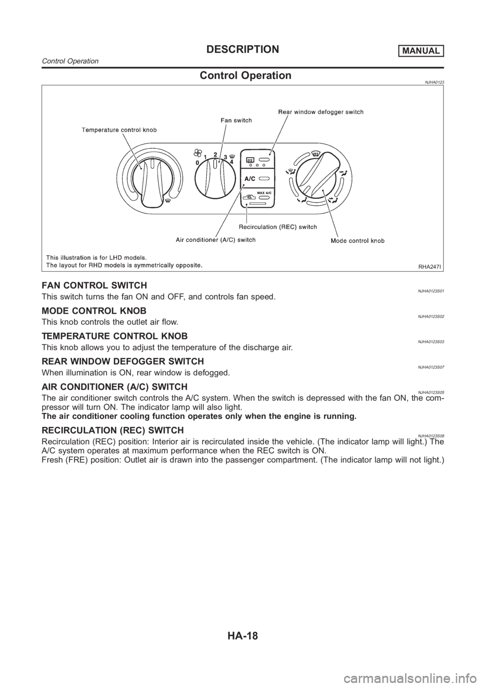
Control OperationNJHA0123
RHA247I
FAN CONTROL SWITCHNJHA0123S01This switch turns the fan ON and OFF, and controls fan speed.
MODE CONTROL KNOBNJHA0123S02This knob controls the outlet air flow.
TEMPERATURE CONTROL KNOBNJHA0123S03This knob allows you to adjust the temperature of the discharge air.
REAR WINDOW DEFOGGER SWITCHNJHA0123S07When illumination is ON, rear window is defogged.
AIR CONDITIONER (A/C) SWITCHNJHA0123S05The air conditioner switch controls the A/C system. When the switch is depressed with the fan ON, the com-
pressor will turn ON. The indicator lamp will also light.
The air conditioner cooling function operates only when the engine is running.
RECIRCULATION (REC) SWITCHNJHA0123S08Recirculation (REC) position: Interior air is recirculated inside the vehicle. (The indicator lamp will light.) The
A/C system operates at maximum performance when the REC switch is ON.
Fresh (FRE) position: Outlet air is drawn into the passenger compartment.(The indicator lamp will not light.)
DESCRIPTIONMANUAL
Control Operation
HA-18
Page 2970 of 3189
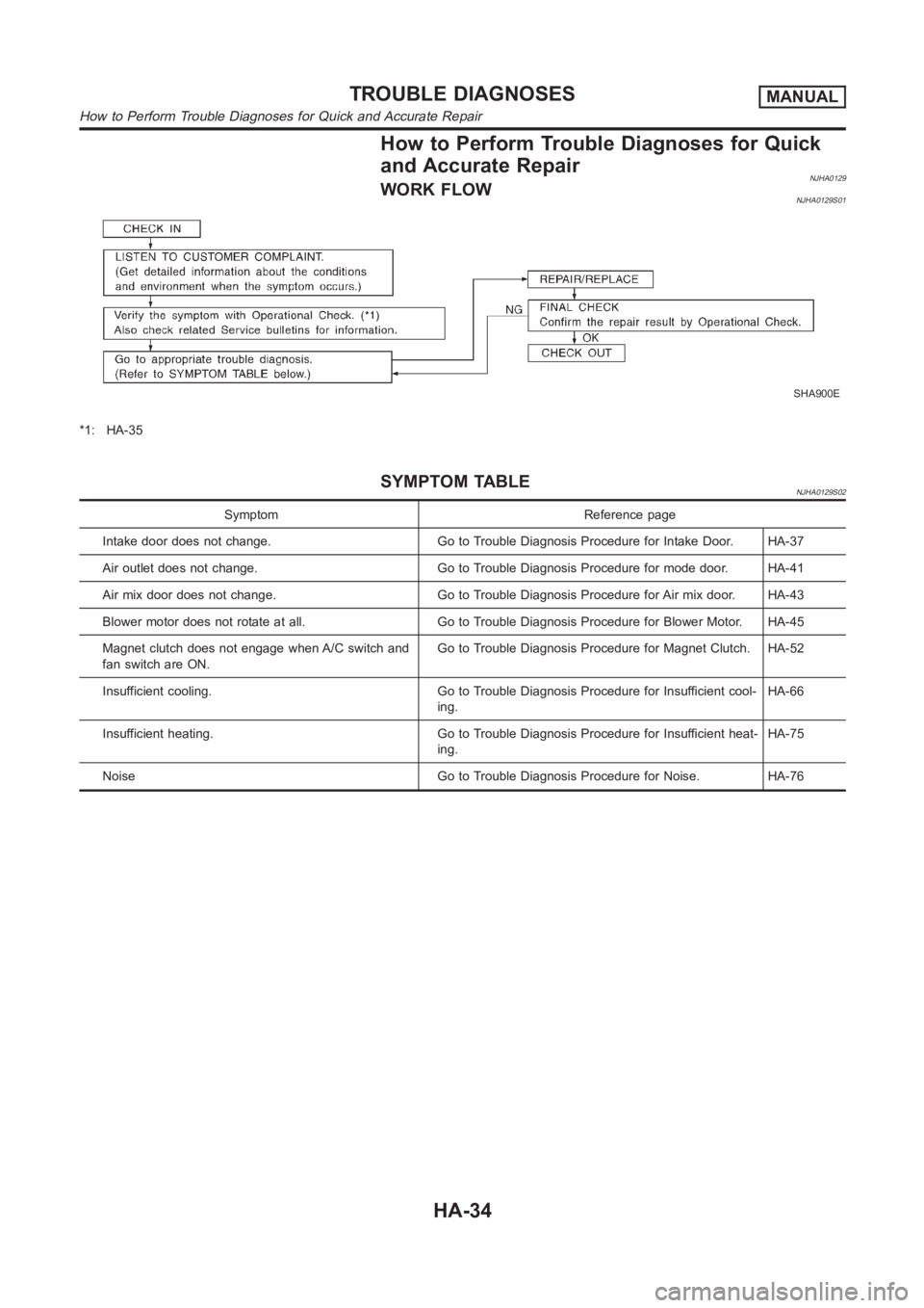
How to Perform Trouble Diagnoses for Quick
and Accurate Repair
NJHA0129WORK FLOWNJHA0129S01
SHA900E
*1: HA-35
SYMPTOM TABLENJHA0129S02
Symptom Reference page
Intake door does not change. Go to Trouble Diagnosis Procedure for Intake Door. HA-37
Air outlet does not change. Go to Trouble Diagnosis Procedure for mode door. HA-41
Air mix door does not change. Go to Trouble Diagnosis Procedure for Air mix door. HA-43
Blower motor does not rotate at all. Go to Trouble Diagnosis Procedure for Blower Motor. HA-45
Magnet clutch does not engage when A/C switch and
fan switch are ON.Go to Trouble Diagnosis Procedure for Magnet Clutch. HA-52
Insufficient cooling. Go to Trouble Diagnosis Procedure for Insufficient cool-
ing.HA-66
Insufficient heating. Go to Trouble Diagnosis Procedure for Insufficientheat-
ing.HA-75
Noise Go to Trouble Diagnosis Procedure for Noise. HA-76
TROUBLE DIAGNOSESMANUAL
How to Perform Trouble Diagnoses for Quick and Accurate Repair
HA-34
Page 2972 of 3189
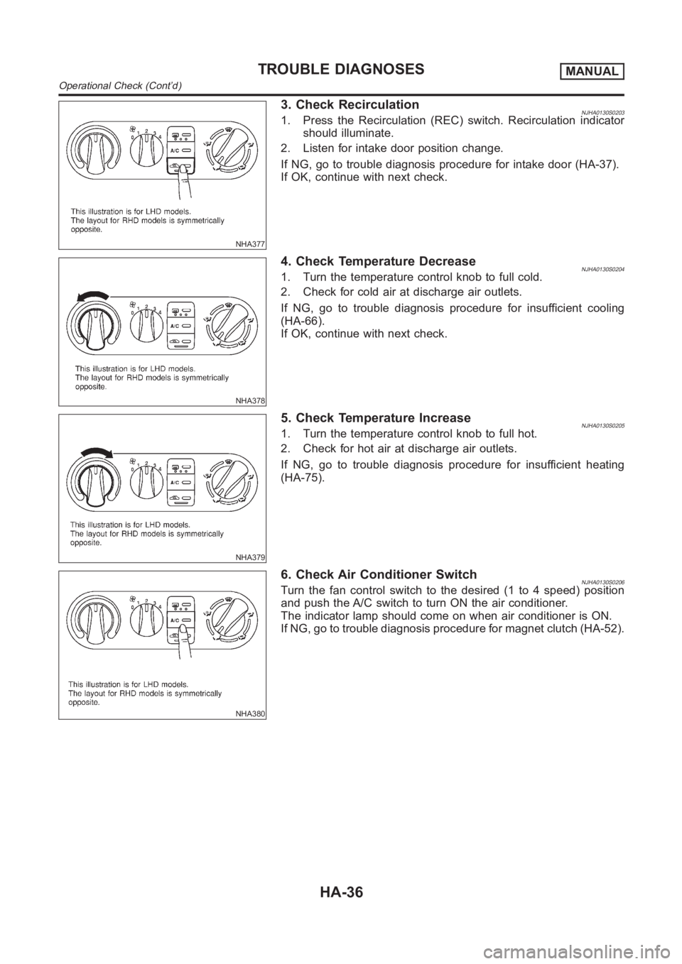
NHA377
3. Check RecirculationNJHA0130S02031. Press the Recirculation (REC) switch. Recirculation indicator
should illuminate.
2. Listen for intake door position change.
If NG, go to trouble diagnosis procedure for intake door (HA-37).
If OK, continue with next check.
NHA378
4. Check Temperature DecreaseNJHA0130S02041. Turn the temperature control knob to full cold.
2. Check for cold air at discharge air outlets.
If NG, go to trouble diagnosis procedure for insufficient cooling
(HA-66).
If OK, continue with next check.
NHA379
5. Check Temperature IncreaseNJHA0130S02051. Turn the temperature control knob to full hot.
2. Check for hot air at discharge air outlets.
If NG, go to trouble diagnosis procedure for insufficient heating
(HA-75).
NHA380
6. Check Air Conditioner SwitchNJHA0130S0206Turn the fan control switch to the desired (1 to 4 speed) position
and push the A/C switch to turn ON the air conditioner.
The indicator lamp should come on when air conditioner is ON.
If NG, go to trouble diagnosis procedure for magnet clutch (HA-52).
TROUBLE DIAGNOSESMANUAL
Operational Check (Cont’d)
HA-36
Page 3005 of 3189
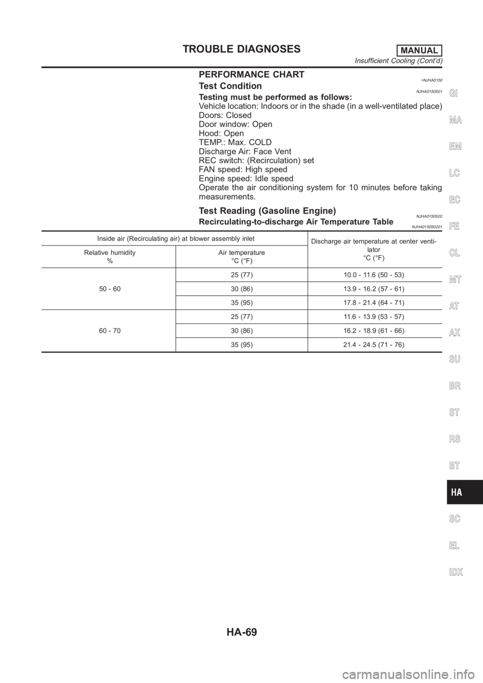
PERFORMANCE CHART=NJHA0150Test ConditionNJHA0150S01Testing must be performed as follows:
Vehicle location: Indoors or in the shade (in a well-ventilated place)
Doors: Closed
Door window: Open
Hood: Open
TEMP.: Max. COLD
Discharge Air: Face Vent
REC switch: (Recirculation) set
FAN speed: High speed
Engine speed: Idle speed
Operate the air conditioning system for 10 minutes before taking
measurements.
Test Reading (Gasoline Engine)NJHA0150S02Recirculating-to-discharge Air Temperature TableNJHA0150S0201
Inside air (Recirculating air) at blower assembly inlet
Discharge air temperature at center venti-
lator
°C (°F) Relative humidity
%Air temperature
°C (°F)
50 - 6025 (77) 10.0 - 11.6 (50 - 53)
30 (86) 13.9 - 16.2 (57 - 61)
35 (95) 17.8 - 21.4 (64 - 71)
60 - 7025 (77) 11.6 - 13.9 (53 - 57)
30 (86) 16.2 - 18.9 (61 - 66)
35 (95) 21.4 - 24.5 (71 - 76)
GI
MA
EM
LC
EC
FE
CL
MT
AT
AX
SU
BR
ST
RS
BT
SC
EL
IDX
TROUBLE DIAGNOSESMANUAL
Insufficient Cooling (Cont’d)
HA-69
Page 3007 of 3189
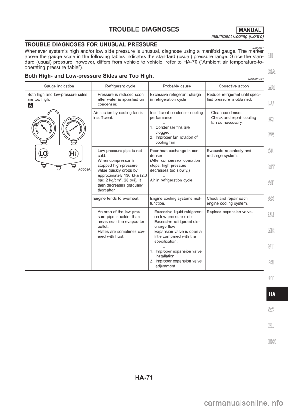
TROUBLE DIAGNOSES FOR UNUSUAL PRESSURENJHA0151Whenever system’s high and/or low side pressure is unusual, diagnose using a manifold gauge. The marker
above the gauge scale in the following tables indicates the standard (usual) pressure range. Since the stan-
dard (usual) pressure, however, differs from vehicle to vehicle, refer toHA-70 (“Ambient air temperature-to-
operating pressure table”).
Both High- and Low-pressure Sides are Too High.NJHA0151S01
Gauge indication Refrigerant cycle Probable cause Corrective action
Both high and low-pressure sides
are too high.
AC359A
Pressure is reduced soon
after water is splashed on
condenser.Excessive refrigerant charge
in refrigeration cycleReduce refrigerant until speci-
fied pressure is obtained.
Air suction by cooling fan is
insufficient.Insufficient condenser cooling
performance
"
1. Condenser fins are
clogged.
2. Improper fan rotation of
cooling fanClean condenser.
Check and repair cooling
fan as necessary.
Low-pressure pipe is not
cold.
When compressor is
stopped high-pressure
value quickly drops by
approximately 196 kPa (2.0
bar, 2 kg/cm
2, 28 psi). It
then decreases gradually
thereafter.Poor heat exchange in con-
denser
(After compressor operation
stops, high pressure
decreases too slowly.)
"
Air in refrigeration cycleEvacuate repeatedly and
recharge system.
Engine tends to overheat. Engine cooling systems mal-
function.Check and repair each
engine cooling system.
An area of the low-pres-
sure pipe is colder than
areas near the evaporator
outlet.
Plates are sometimes cov-
ered with frost.Excessive liquid refrigerant
on low-pressure side
Excessive refrigerant dis-
charge flow
Expansion valve is open a
little compared with the
specification.
"
1. Improper expansion valve
installation
2. Improper expansion valve
adjustmentReplace expansion valve.
GI
MA
EM
LC
EC
FE
CL
MT
AT
AX
SU
BR
ST
RS
BT
SC
EL
IDX
TROUBLE DIAGNOSESMANUAL
Insufficient Cooling (Cont’d)
HA-71
Page 3029 of 3189
SHA708EA
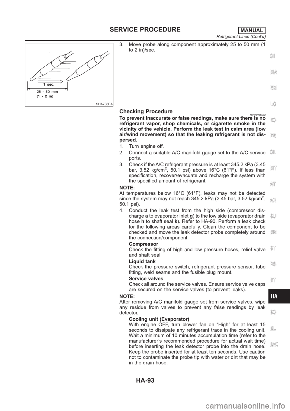
3. Move probe along component approximately 25 to 50 mm (1
to 2 in)/sec.
Checking ProcedureNJHA0168S03To prevent inaccurate or false readings, make sure there is no
refrigerant vapor, shop chemicals, or cigarette smoke in the
vicinity of the vehicle. Perform the leak test in calm area (low
air/wind movement) so that the leaking refrigerant is not dis-
persed.
1. Turn engine off.
2. Connect a suitable A/C manifold gauge set to the A/C service
ports.
3. Check if the A/C refrigerant pressure is at least 345.2 kPa (3.45
bar, 3.52 kg/cm
2, 50.1 psi) above 16°C (61°F). If less than
specification, recover/evacuate and recharge the system with
the specified amount of refrigerant.
NOTE:
At temperatures below 16°C (61°F), leaks may not be detected
since the system may not reach 345.2 kPa (3.45 bar, 3.52 kg/cm
2,
50.1 psi).
4. Conduct the leak test from the high side (compressor dis-
chargeato evaporator inletg) to the low side (evaporator drain
hosehto shaft sealk). Refer to HA-90. Perform a leak check
for the following areas carefully. Clean the component to be
checked and move the leak detector probe completely around
the connection/component.
Compressor
Check the fitting of high and low pressure hoses, relief valve
and shaft seal.
Liquid tank
Check the pressure switch, refrigerant pressure sensor, tube
fitting, weld seams and the fusible plug mount.
Service valves
Check all around the service valves. Ensure service valve caps
are secured on the service valves (to prevent leaks).
NOTE:
After removing A/C manifold gauge set from service valves, wipe
any residue from valves to prevent any false readings by leak
detector.
Cooling unit (Evaporator)
With engine OFF, turn blower fan on “High” for at least 15
seconds to dissipate any refrigerant trace in the cooling unit.
Wait a minimum of 10 minutes accumulation time (refer to the
manufacturer’s recommended procedure for actual wait time)
before inserting the leak detector probe into the drain hose.
Keep the probe inserted for at least ten seconds. Use caution
not to contaminate the probe tip with water or dirt that may be
in the drain hose.
GI
MA
EM
LC
EC
FE
CL
MT
AT
AX
SU
BR
ST
RS
BT
SC
EL
IDX
SERVICE PROCEDUREMANUAL
Refrigerant Lines (Cont’d)
HA-93
Page 3178 of 3189
COOL/F - Wiring diagram
(QG engine)................................EC-328, EC-601
COOL/F - Wiring diagram (YD engine) ........EC-130
Coolant mixture ratio......................................MA-21
Cooling circuit (engine).............................LC-12, 36
Cooling fan control (YD engine)...................EC-130
Cooling fan control system .......................LC-17, 42
Cooling fan motor (QG engine) .....EC-335, EC-608
Coupling sleeve (M/T)........................MT-31, 55, 93
Crankcase emission control system -
See positive crankcase ventilation
(YD engine).................................................EC-19
Crankcase ventilation system - See
Positive crankcase ventilation
(QG engine)................................EC-403, EC-722
Crankcase ventilation system - See
Positive crankcase ventilation
(YD engine).................................................EC-19
Crankshaft (QG engine).................................EM-71
Crankshaft (YD engine) .................................EM-75
Crankshaft position sensor (POS)
(QG engine)................................EC-235, EC-556
Crankshaft position sensor (TDC)
(YD engine).................................................EC-99
Cylinder block (QG engine) ...........................EM-70
Cylinder block (YD engine) ............................EM-66
Cylinder block boring (QG engine) ................EM-88
Cylinder block boring(QR) .............................EM-89
Cylinder head (QG engine)............................EM-57
Cylinder head (YD engine) ............................EM-45
Cylinder head bolt tightening
(QG engine)................................................EM-59
D
Data link connector
(QG engine) ...EC-398, EC-399, EC-717, EC-718
Data link connector for Consult
(QG engine)..................................EC-90, EC-468
Data link connector for Consult
(YD engine).................................................EC-39
Daytime light system.......................................EL-46
DEF - Wiring diagram ...................................EL-176
Diagnosis sensor unit .....................................RS-26
Diagnostic trouble code (DTC) for OBD
system (QG engine) ......................EC-10, EC-39,
EC-407, EC-430
Diagnostic trouble code (DTC) for OBD
system (YD engine) ................................EC-4, 34
Diagnostic trouble code (DTC) inspec-
tion priority chart (QG engine) .....EC-62, EC-441
Differential gear (FF M/T) ....MT-31, 43, 55, 93, 107
Dimensions <0011001100110011001100110011001100110011001100110011001100110011001100110011001100110011001100110011001100110011001100110011001100110011001100110011001100110011001100110011001100110011001100110011001100
1100110011[.GI-44
Dome light - See Interior lamp .......................EL-80
Door glass <0011001100110011001100110011001100110011001100110011001100110011001100110011001100110011001100110011001100110011001100110011001100110011001100110011001100110011001100110011001100110011001100110011001100
11001100110011[.BT-17
Door lock <0011001100110011001100110011001100110011001100110011001100110011001100110011001100110011001100110011001100110011001100110011001100110011001100110011001100110011001100110011001100110011001100110011001100
110011001100110011[..BT-21
Door mirror <0011001100110011001100110011001100110011001100110011001100110011001100110011001100110011001100110011001100110011001100110011001100110011001100110011001100110011001100110011001100110011001100110011001100
1100110011[.BT-72
Door trim <0011001100110011001100110011001100110011001100110011001100110011001100110011001100110011001100110011001100110011001100110011001100110011001100110011001100110011001100110011001100110011001100110011001100
110011001100110011[..BT-39
Door, front <0011001100110011001100110011001100110011001100110011001100110011001100110011001100110011001100110011001100110011001100110011001100110011001100110011001100110011001100110011001100110011001100110011001100
1100110011[..BT-16
Door, rear <0011001100110011001100110011001100110011001100110011001100110011001100110011001100110011001100110011001100110011001100110011001100110011001100110011001100110011001100110011001100110011001100110011001100
11001100110011[..BT-16Drive belt (QG engine) ...................................EM-11
Drive shaft (front)............................................AX-10
Dropping resistor (A/T) ....................AT-171, AT-395
DTC work support (QG engine) .....................EC-97
Dual pressure switch (manual A/C) ...............HA-12
Dual pressure switch ......ATC-15, ATC-86, ATC-144
Duct and grilles...........................................ATC-131
E
ECCS-D control module
(YD engine) ........EC-66, 116, 175, 177, 181, 183
ECM input/output signal
(QG engine)..................................EC-81, EC-460
ECM input/output signal (YD engine) ............EC-66
ECM power supply
(QG engine) ...EC-111, EC-269, EC-488, EC-573
ECM/PW - Wiring diagram
(QG engine)................................EC-270, EC-574
ECTS - Wiring diagram
(QG engine)................................EC-147, EC-505
ECTS - Wiring diagram (YD engine)..............EC-84
EGR volume control valve (YD engine) .......EC-197
EGRC1 - Wiring diagram (YD engine) .........EC-199
Electric sun roof ............................................EL-249
Electric throttle control actuator
(QG engine) ................EC-277, EC-279, EC-292,
EC-577, EC-580, EC-593
Electrical diagnoses.........................................GI-22
Electrical load signal circuit
(QG engine)................................EC-393, EC-712
Electrical unit ................................................Foldout
Electrical units location .................................EL-543
Electronic fuel injection pump
(YD engine) ...............EC-25, 118, 124, 145, 151,
157, 163, 169, 185
Electronic ignition (EI) system
(QG engine)..................................EC-25, EC-420
Engine compartment .......................................BT-75
Engine control circuit diagram
(QG engine)..................................EC-79, EC-458
Engine control circuit diagram
(YD engine).................................................EC-14
Engine control component parts loca-
tion (QG engine)...........................EC-75, EC-454
Engine control component parts loca-
tion (YD engine) ..........................................EC-11
Engine control module (ECM)
(QG engine)................................EC-266, EC-570
Engine control module (ECM)
(YD engine) ........EC-66, 116, 175, 177, 181, 183
Engine control system diagram and
chart (QG engine) ........................EC-21, EC-416
Engine control system diagram and
chart (YD engine) .......................................EC-15
Engine coolant temperature sensor
(ECTS) (QG engine) ..................EC-145, EC-503
Engine coolant temperature sensor
(ECTS) (YD engine) ...................................EC-84
ALPHABETICAL INDEX
IDX-4