cooling fan NISSAN ALMERA N16 2003 Electronic Manual PDF
[x] Cancel search | Manufacturer: NISSAN, Model Year: 2003, Model line: ALMERA N16, Model: NISSAN ALMERA N16 2003Pages: 3189, PDF Size: 54.76 MB
Page 1983 of 3189
ATC-3
C
D
E
F
G
H
I
K
L
MA
B
AT C SUNLOAD SENSOR ...............................................117
Removal and Installation ....................................... 117
INTAKE SENSOR CIRCUIT ....................................118
Removal and Installation ....................................... 118
BLOWER UNIT ........................................................119
Removal and Installation ....................................... 119
REMOVAL .......................................................... 119
INSTALLATION .................................................. 119
Disassembly and Assembly .................................. 119
BLOWER MOTOR .................................................. 120
Removal and Installation ...................................... 120
INTAKE DOOR MOTOR ......................................... 121
Removal and Installation ...................................... 121
HEATER & COOLING UNIT ASSEMBLY .............. 122
Removal and Installation ...................................... 122
REMOVAL ......................................................... 122
INSTALLATION ................................................. 123
Disassembly and Assembly ................................. 123
MODE DOOR MOTOR ........................................... 125
Removal and Installation ...................................... 125
AIR MIX DOOR MOTOR ......................................... 126
Removal and Installation ...................................... 126
FAN CONTROL AMPLIFIER .................................. 127
Removal and Installation ...................................... 127
VENTILATION AIR FILTER .................................... 128
Removal and Installation ...................................... 128
FUNCTION ........................................................ 128
REPLACEMENT TIMING .................................. 128
REPLACEMENT AND PROCEDURES ............ 128
HEATER CORE ...................................................... 129
Removal and Installation ...................................... 129
DUCTS AND GRILLES .......................................... 130
Removal and Installation ...................................... 130
VENTILATOR DUCT, DEFROSTER NOZZLE
AND DEFROSTER DUCTS .............................. 130
CENTER VENTILATOR GRILLE ...................... 130
SIDE VENTILATOR GRILLE ............................. 130
FOOT DUCT ..................................................... 130
FLOOR DUCT ................................................... 131
REFRIGERANT LINES ........................................... 132
HFC-134a (R-134a) Service Procedure ............... 132
SETTING OF SERVICE TOOLS AND EQUIP-
MENT ................................................................ 132Components .........................................................134
Compressor ..........................................................136
REMOVAL .........................................................136
INSTALLATION .................................................137
Compressor Clutch .............................................. .138
REMOVAL .........................................................138
INSTALLATION .................................................139
Low-pressure Flexible Hose .................................141
REMOVAL .........................................................141
INSTALLATION .................................................141
High-pressure Flexible Hose ................................141
REMOVAL .........................................................141
INSTALLATION .................................................142
High-pressure Pipe ...............................................142
REMOVAL .........................................................142
INSTALLATION .................................................142
Refrigerant Pressure Sensor ................................142
REMOVAL AND INSTALLATION ......................142
Dual-pressure Switch ...........................................143
REMOVAL AND INSTALLATION ......................143
Condenser Assembly ...........................................143
REMOVAL .........................................................143
INSTALLATION .................................................143
Evaporator ............................................................144
REMOVAL .........................................................144
INSTALLATION .................................................144
Expansion Valve ...................................................144
REMOVAL .........................................................144
INSTALLATION .................................................144
Checking for Refrigerant Leaks ............................145
Checking System for Leaks Using the Fluorescent
Leak Detector .......................................................145
Dye Injection .........................................................146
Electronic Refrigerant Leak Detector ....................146
PRECAUTIONS FOR HANDLING LEAK
DETECTOR .......................................................146
CHECKING PROCEDURE ...............................147
SERVICE DATA AND SPECIFICATIONS (SDS) ....149
Compressor ..........................................................149
Lubricant ...............................................................149
Refrigerant ............................................................149
Engine Idling Speed .............................................149
Belt Tension ..........................................................149
Page 1996 of 3189
ATC-16
REFRIGERATION SYSTEM
CSV613 Variable Displacement Compressor
EJS001Z2
GENERAL INFORMATION
1. The CSV613 compressor differs from previous units. The vent temperatures of the CSV613 compressor
do not drop too far below 5°C (41°F) when:
Evaporator intake air temperature is less than 20°C (68°F).
Engine is running at speeds less than 1,500 rpm.
This is because the CSV613 compressor provides a means of “capacity” control.
2. The CSV613 compressor provides refrigerant control under varying conditions. During cold winters, it may
not produce high refrigerant pressure discharge (compared to previous units) when used with air condi-
tioning systems.
3. A “clanking” sound may occasionally be heard during refrigerant charge. The sound indicates that the tilt
angle of the swash plate has changed and is not a problem.
4. For air conditioning systems with the CSV613 compressor, the clutch remains engaged unless: the sys-
tem main switch, fan switch or ignition switch is turned OFF. When ambient (outside) temperatures are
low or when the amount of refrigerant is insufficient, the clutch is disengaged to protect the compressor.
5. A constant range of suction pressure is maintained when engine speed is greater than a certain value. It
normally ranges from 147 to 177 kPa (1.47 to 1.77 bar, 1.5 to 1.8 kg/cm
2 , 21 to 26 psi) under varying con-
ditions.
In previous compressors, however, suction pressure was reduced with increases in engine speed.
DESCRIPTION
General
The variable compressor is basically a swash plate type that changes piston stroke in response to the required
cooling capacity.
Page 2009 of 3189
TROUBLE DIAGNOSIS
ATC-29
C
D
E
F
G
H
I
K
L
MA
B
AT C
TROUBLE DIAGNOSISPFP:00004
How to Perform Trouble Diagnoses for Quick and Accurate RepairEJS001ZC
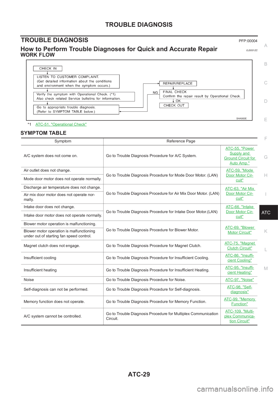
WORK FLOW
SYMPTOM TABLE
*1AT C - 5 1 , "Operational Check"
SHA900E
Symptom Reference Page
A/C system does not come on. Go to Trouble Diagnosis Procedure for A/C System.ATC-55, "
Power
Supply and
Ground Circuit for
Auto Amp."
Air outlet does not change.
Go to Trouble Diagnosis Procedure for Mode Door Motor. (LAN)AT C - 5 9 , "Mode
Door Motor Cir-
cuit"Mode door motor does not operate normally.
Discharge air temperature does not change.
Go to Trouble Diagnosis Procedure for Air Mix Door Motor. (LAN)ATC-63, "
Air Mix
Door Motor Cir-
cuit"Air mix door motor does not operate nor-
mally.
Intake door does not change.
Go to Trouble Diagnosis Procedure for Intake Door Motor.(LAN)AT C - 6 6 , "
Intake
Door Motor Cir-
cuit"Intake door motor does not operate normally.
Blower motor operation is malfunctioning.
Go to Trouble Diagnosis Procedure for Blower Motor.ATC-69, "
Blower
Motor Circuit"Blower motor operation is malfunctioning
under out of starting fan speed control.
Magnet clutch does not engage. Go to Trouble Diagnosis Procedure for Magnet Clutch.AT C - 7 5 , "
Magnet
Clutch Circuit"
Insufficient cooling Go to Trouble Diagnosis Procedure for Insufficient Cooling.AT C - 8 6 , "Insuffi-
cient Cooling"
Insufficient heating Go to Trouble Diagnosis Procedure for Insufficient Heating.AT C - 9 5 , "Insuffi-
cient Heating"
Noise Go to Trouble Diagnosis Procedure for Noise.ATC-97, "Noise"
Self-diagnosis can not be performed. Go to Trouble Diagnosis Procedure for Self-diagnosis.AT C - 9 8 , "Self-
diagnosis"
Memory function does not operate. Go to Trouble Diagnosis Procedure for Memory Function.AT C - 9 9 , "Memory
Function"
A/C system cannot be controlled.Go to Trouble Diagnosis Procedure for Multiplex Communication
Circuit.ATC-109, "
Multi-
plex Communica-
tion Circuit"
Page 2051 of 3189
TROUBLE DIAGNOSIS
ATC-71
C
D
E
F
G
H
I
K
L
MA
B
AT C
In the most extreme case (very low ambient) the blower starting delay will be 150 seconds as described
above. After this delay, the blower will operate at low speed until the engine coolant temperature rises above
56°C (133°F), at which time the blower speed will increase to the objective speed.
Start Up From Usual or HOT SOAK Condition (Automatic mode)
The blower will begin operation momentarily after the A/C button is pushed. The blower speed will gradually
rise to the objective speed over a time period of 3 seconds or less (actual time depends on the objective
blower speed).
Blower Speed Compensation
Sunload
When the in-vehicle temperature and the set temperature are very close, the blower will be operating at low
speed. The low speed will vary depending on the sunload. During conditions of low or no sunload, the blower
low speed is usual low speed (approx. 4V). During high sunload conditions, the auto amp causes the blower
fan speed to increase.(Approx. 7V)
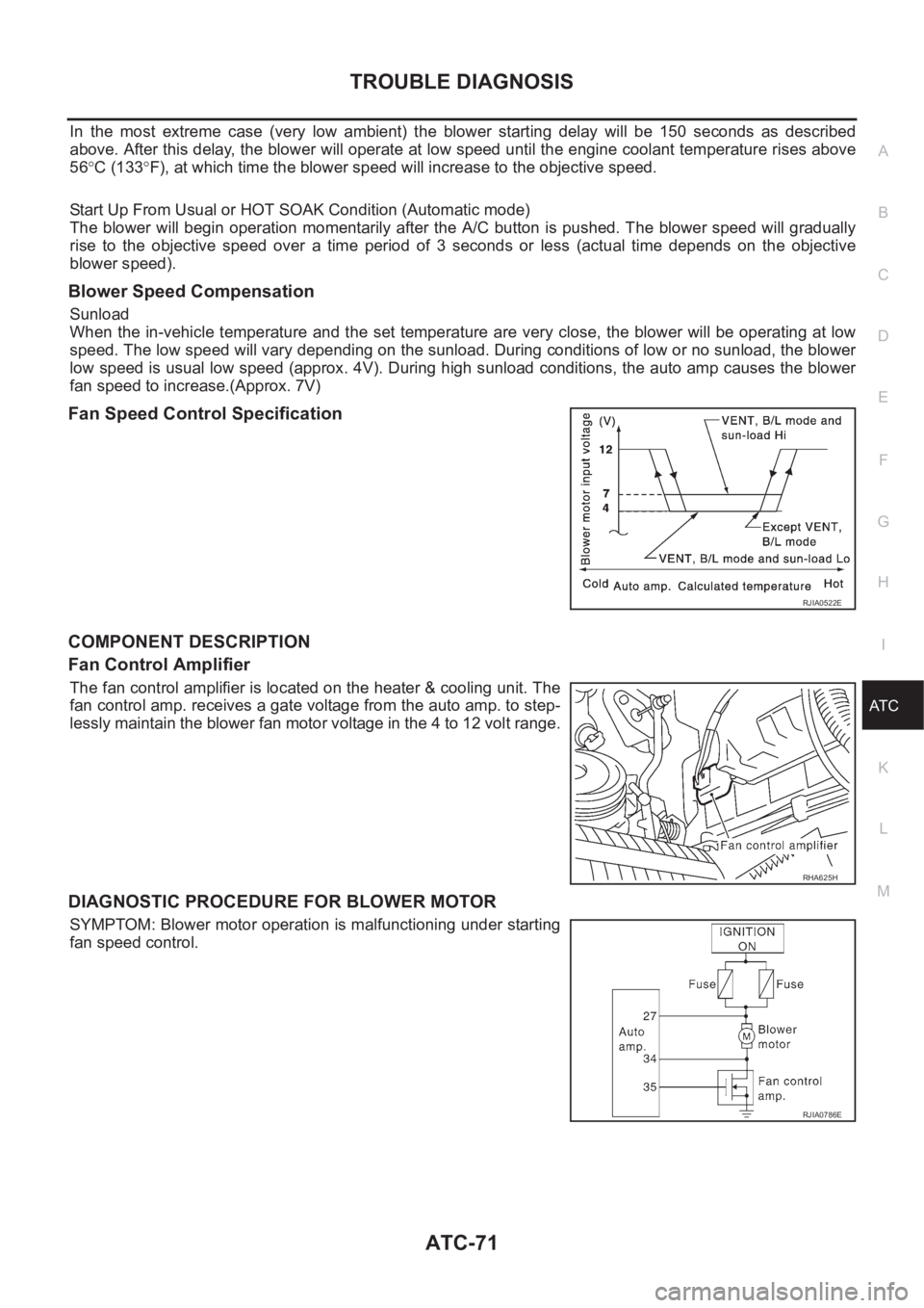
Fan Speed Control Specification
COMPONENT DESCRIPTION
Fan Control Amplifier
The fan control amplifier is located on the heater & cooling unit. The
fan control amp. receives a gate voltage from the auto amp. to step-
lessly maintain the blower fan motor voltage in the 4 to 12 volt range.
DIAGNOSTIC PROCEDURE FOR BLOWER MOTOR
SYMPTOM: Blower motor operation is malfunctioning under starting
fan speed control.
RJIA0522E
RHA625H
RJIA0786E
Page 2072 of 3189
ATC-92
TROUBLE DIAGNOSIS
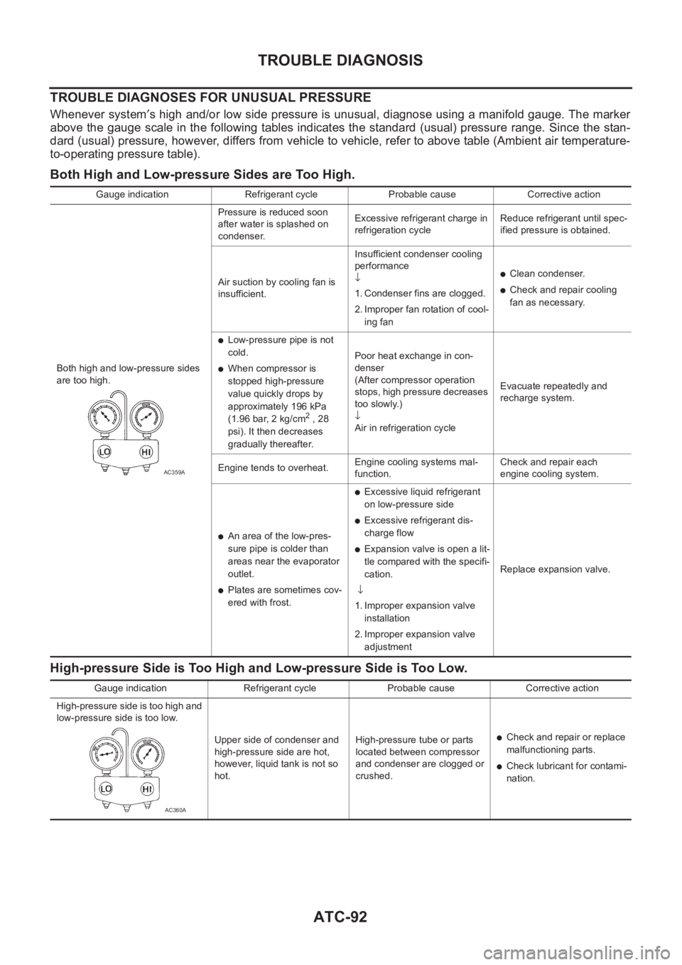
TROUBLE DIAGNOSES FOR UNUSUAL PRESSURE
Whenever system′s high and/or low side pressure is unusual, diagnose using a manifold gauge. The marker
above the gauge scale in the following tables indicates the standard (usual) pressure range. Since the stan-
dard (usual) pressure, however, differs from vehicle to vehicle, refer to above table (Ambient air temperature-
to-operating pressure table).
Both High and Low-pressure Sides are Too High.
High-pressure Side is Too High and Low-pressure Side is Too Low.
Gauge indication Refrigerant cycle Probable cause Corrective action
Both high and low-pressure sides
are too high.Pressure is reduced soon
after water is splashed on
condenser.Excessive refrigerant charge in
refrigeration cycleReduce refrigerant until spec-
ified pressure is obtained.
Air suction by cooling fan is
insufficient.Insufficient condenser cooling
performance
↓
1. Condenser fins are clogged.
2. Improper fan rotation of cool-
ing fan
●Clean condenser.
●Check and repair cooling
fan as necessary.
●Low-pressure pipe is not
cold.
●When compressor is
stopped high-pressure
value quickly drops by
approximately 196 kPa
(1.96 bar, 2 kg/cm
2 , 28
psi). It then decreases
gradually thereafter.Poor heat exchange in con-
denser
(After compressor operation
stops, high pressure decreases
too slowly.)
↓
Air in refrigeration cycleEvacuate repeatedly and
recharge system.
Engine tends to overheat.Engine cooling systems mal-
function.Check and repair each
engine cooling system.
●An area of the low-pres-
sure pipe is colder than
areas near the evaporator
outlet.
●Plates are sometimes cov-
ered with frost.
●Excessive liquid refrigerant
on low-pressure side
●Excessive refrigerant dis-
charge flow
●Expansion valve is open a lit-
tle compared with the specifi-
cation.
↓
1. Improper expansion valve
installation
2. Improper expansion valve
adjustmentReplace expansion valve.
AC359A
Gauge indication Refrigerant cycle Probable cause Corrective action
High-pressure side is too high and
low-pressure side is too low.
Upper side of condenser and
high-pressure side are hot,
however, liquid tank is not so
hot.High-pressure tube or parts
located between compressor
and condenser are clogged or
crushed.
●Check and repair or replace
malfunctioning parts.
●Check lubricant for contami-
nation.
AC360A
Page 2099 of 3189
BLOWER UNIT
ATC-119
C
D
E
F
G
H
I
K
L
MA
B
AT C
BLOWER UNITPFP:27200
Removal and InstallationEJS00206
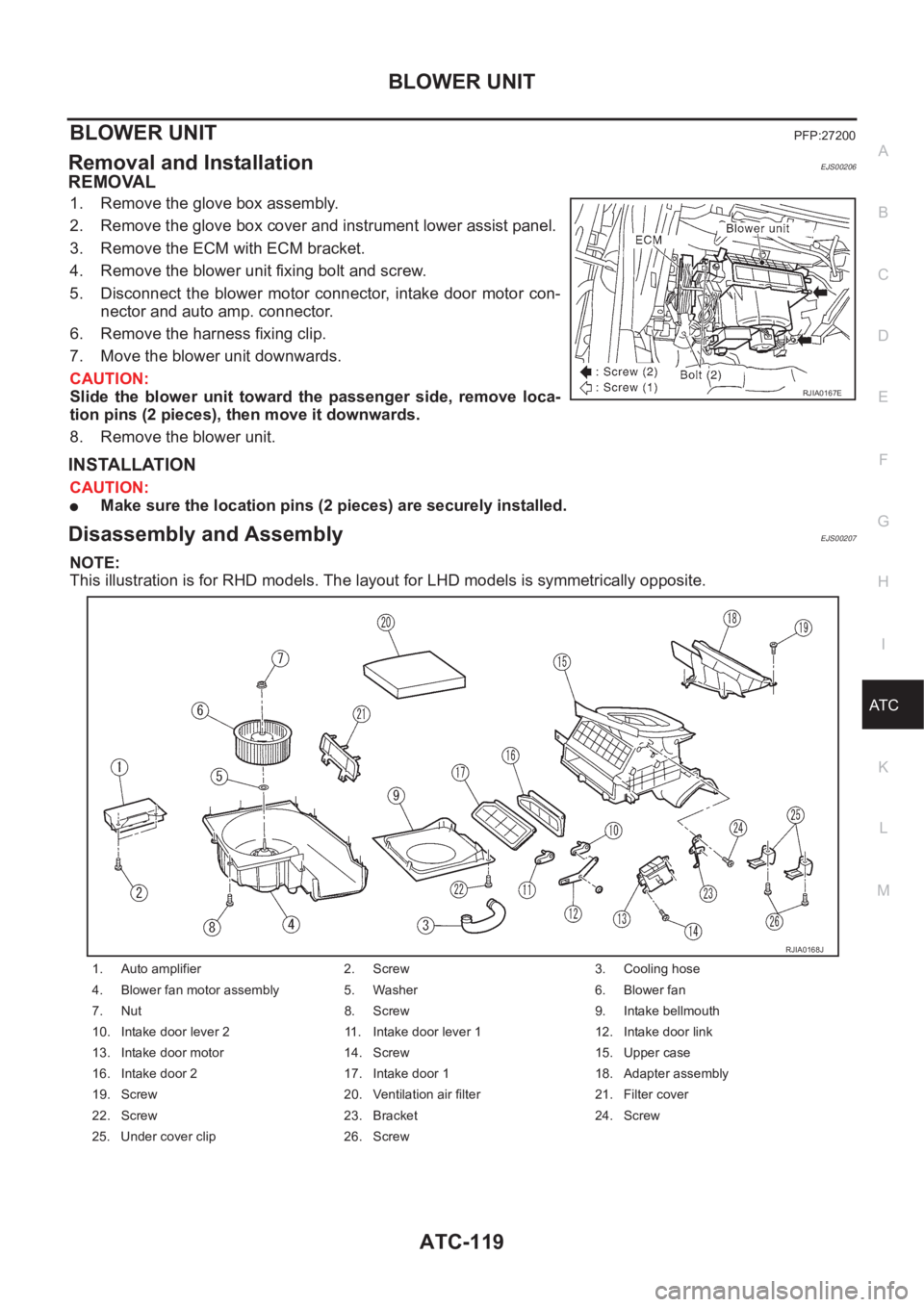
REMOVAL
1. Remove the glove box assembly.
2. Remove the glove box cover and instrument lower assist panel.
3. Remove the ECM with ECM bracket.
4. Remove the blower unit fixing bolt and screw.
5. Disconnect the blower motor connector, intake door motor con-
nector and auto amp. connector.
6. Remove the harness fixing clip.
7. Move the blower unit downwards.
CAUTION:
Slide the blower unit toward the passenger side, remove loca-
tion pins (2 pieces), then move it downwards.
8. Remove the blower unit.
INSTALLATION
CAUTION:
●Make sure the location pins (2 pieces) are securely installed.
Disassembly and AssemblyEJS00207
NOTE:
This illustration is for RHD models. The layout for LHD models is symmetrically opposite.
RJIA0167E
1. Auto amplifier 2. Screw 3. Cooling hose
4. Blower fan motor assembly 5. Washer 6. Blower fan
7. Nut 8. Screw 9. Intake bellmouth
10. Intake door lever 2 11. Intake door lever 1 12. Intake door link
13. Intake door motor 14. Screw 15. Upper case
16. Intake door 2 17. Intake door 1 18. Adapter assembly
19. Screw 20. Ventilation air filter 21. Filter cover
22. Screw 23. Bracket 24. Screw
25. Under cover clip 26. Screw
RJIA0168J
Page 2100 of 3189
ATC-120
BLOWER MOTOR
BLOWER MOTOR
PFP:27226
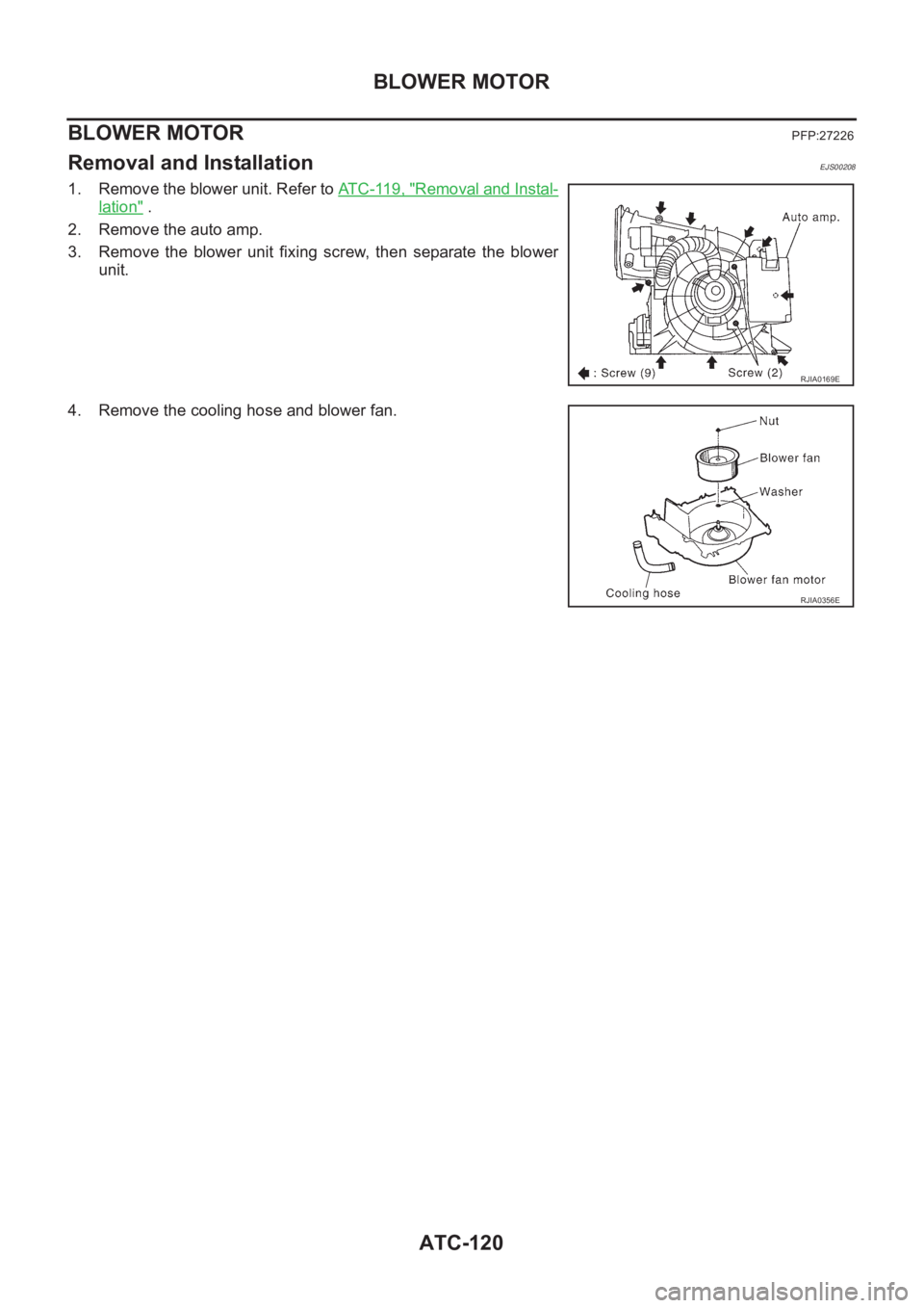
Removal and InstallationEJS00208
1. Remove the blower unit. Refer to AT C - 11 9 , "Removal and Instal-
lation" .
2. Remove the auto amp.
3. Remove the blower unit fixing screw, then separate the blower
unit.
4. Remove the cooling hose and blower fan.
RJIA0169E
RJIA0356E
Page 2104 of 3189

ATC-124
HEATER & COOLING UNIT ASSEMBLY
16. Mode door link 2 17. Screw 18. Mode door lever 1
19. Fan control amp. 20. Screw 21. Mode door motor
22. Screw 23. Screw 24. Air mix door motor
25. Screw 26. Actuator bracket 27. Screw
28. Mode door link 29. Air mix door lever 30. Screw
31. Heater core 32. Evaporator 33. Expansion valve
34. Bolt 35. Cooler grommet 36. Instrument bracket
37. Drain hose 38. Lower case 39. Screw
Page 2127 of 3189
REFRIGERANT LINES
ATC-147
C
D
E
F
G
H
I
K
L
MA
B
AT C
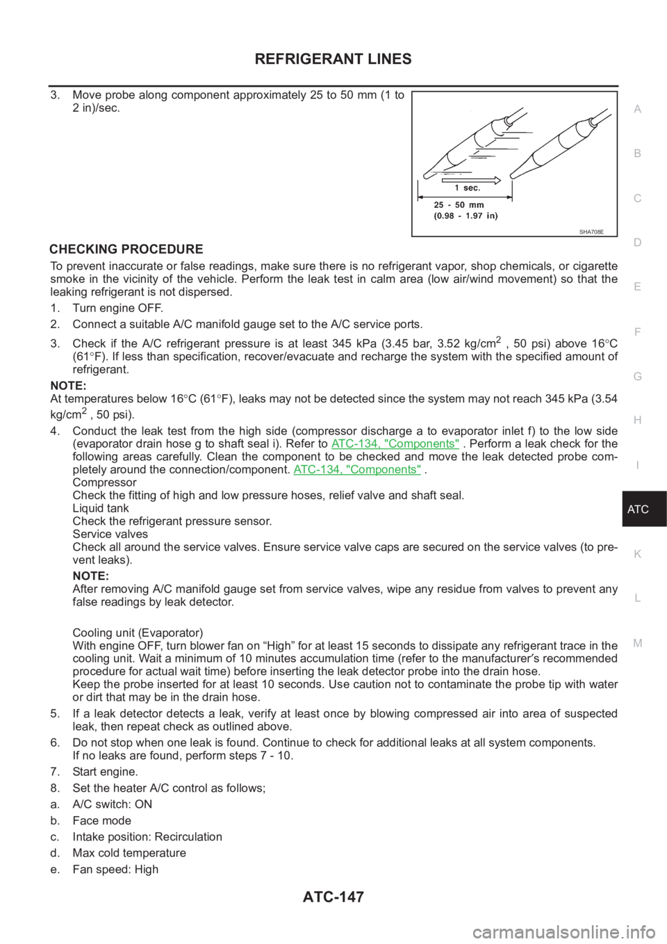
3. Move probe along component approximately 25 to 50 mm (1 to
2 in)/sec.
CHECKING PROCEDURE
To prevent inaccurate or false readings, make sure there is no refrigerant vapor, shop chemicals, or cigarette
smoke in the vicinity of the vehicle. Perform the leak test in calm area (low air/wind movement) so that the
leaking refrigerant is not dispersed.
1. Turn engine OFF.
2. Connect a suitable A/C manifold gauge set to the A/C service ports.
3. Check if the A/C refrigerant pressure is at least 345 kPa (3.45 bar, 3.52 kg/cm
2 , 50 psi) above 16°C
(61°F). If less than specification, recover/evacuate and recharge the system with the specified amount of
refrigerant.
NOTE:
At temperatures below 16°C (61°F), leaks may not be detected since the system may not reach 345 kPa (3.54
kg/cm
2 , 50 psi).
4. Conduct the leak test from the high side (compressor discharge a to evaporator inlet f) to the low side
(evaporator drain hose g to shaft seal i). Refer to AT C - 1 3 4 , "
Components" . Perform a leak check for the
following areas carefully. Clean the component to be checked and move the leak detected probe com-
pletely around the connection/component. ATC-134, "
Components" .
Compressor
Check the fitting of high and low pressure hoses, relief valve and shaft seal.
Liquid tank
Check the refrigerant pressure sensor.
Service valves
Check all around the service valves. Ensure service valve caps are secured on the service valves (to pre-
vent leaks).
NOTE:
After removing A/C manifold gauge set from service valves, wipe any residue from valves to prevent any
false readings by leak detector.
Cooling unit (Evaporator)
With engine OFF, turn blower fan on “High” for at least 15 seconds to dissipate any refrigerant trace in the
cooling unit. Wait a minimum of 10 minutes accumulation time (refer to the manufacturer′s recommended
procedure for actual wait time) before inserting the leak detector probe into the drain hose.
Keep the probe inserted for at least 10 seconds. Use caution not to contaminate the probe tip with water
or dirt that may be in the drain hose.
5. If a leak detector detects a leak, verify at least once by blowing compressed air into area of suspected
leak, then repeat check as outlined above.
6. Do not stop when one leak is found. Continue to check for additional leaks at all system components.
If no leaks are found, perform steps 7 - 10.
7. Start engine.
8. Set the heater A/C control as follows;
a. A/C switch: ON
b. Face mode
c. Intake position: Recirculation
d. Max cold temperature
e. Fan speed: High
SHA708E
Page 2713 of 3189
![NISSAN ALMERA N16 2003 Electronic Manual PDF Terminal
No.Wire
colorConnections Operated condition Voltage (Approximate values)
24 BRWasher switch
(Headlamp washer switch)[Head lamp switch 1st or 2nd posi-
tion]
Washer switch OFF,ON12V,0V
25 G/OR NISSAN ALMERA N16 2003 Electronic Manual PDF Terminal
No.Wire
colorConnections Operated condition Voltage (Approximate values)
24 BRWasher switch
(Headlamp washer switch)[Head lamp switch 1st or 2nd posi-
tion]
Washer switch OFF,ON12V,0V
25 G/OR](/img/5/57350/w960_57350-2712.png)
Terminal
No.Wire
colorConnections Operated condition Voltage (Approximate values)
24 BRWasher switch
(Headlamp washer switch)[Head lamp switch 1st or 2nd posi-
tion]
Washer switch OFF,ON12V,0V
25 G/ORCombination switch
(Turn signal switch)Turn signal switch:
Neutral,Left turn position12V,0V
26 L/BCombination switch
(Turn signal switch)Turn signal switch:
Neutral,Right turn position12V,0V
27 Y/BVehicle security horn relay
(RHD models)When theft warning system:
Armed,Disarmed0V,12V
28 R/Y Interior room lampWhen interior lamp is operated using
remote controller (Lamp switch in
“DOOR” position)12V,0V
29 Y/G Ignition key switch Ignition key is in “ON” position 12V
30 G/R Hazard switch Hazard switch: OFF,ON 12V,0V
31 W Rear window defogger relay[Ignition switch “ON”]
Rear window defogger switch:
OFF,ON12V,0V
32 LG/B Cooling fan relay[Ignition switch“ ON”]
Cooling fan: Operating,Not operat-
ing0V,12V
33 LG/R Cooling fan relay[Ignition switch “ON”]
Cooling fan: Operating,Not operat-
ing0V,12V
34 L/Y Security indicator Ignition switch ON,OFF 12V,0V
39 BR/WRear door switch
(Passenger side)Rear door LH or RH: Open,Closed 0V,12V
41 L Air conditioner relay[Engine is running]
Air conditioner switch: ON,
OFF12V,0V
43 R/WFront door switch
(Driver side)Front door (Driver side):
Open,Closed12V,0V
44 R/WFront door switch
(Passenger side)Front door (Passenger side):
Open,Closed0V,12V
45 R/YRear door switch
(Driver side)Rear door LH or RH: Open,Closed 0V,12V
49 W/L Power source — 12V
50 GPower door super lock actuator
(Rear)Remote controller door lock switch:
Free,Press0V,12V
51 L/R Driver door lock actuatorDoor lock & unlock switch:
Free,Lock0V,12V
52 W/R Door lock actuatorsDoor lock & unlock switch:
Free,Unlock0V,12V
53 B Ground — 0V
54 R/B Door lock actuatorsDoor lock & unlock switch:
Free,Unlock0V,12V
55 W/BPower door super lock actuator
(Front)Remote controller door lock switch:
Free,Unlock0V,12V
56 R/B Power source — 12V
GI
MA
EM
LC
EC
FE
CL
MT
AT
AX
SU
BR
ST
RS
BT
HA
SC
IDX
SMART ENTRANCE CONTROL SYSTEM
Smart Entrance Control Unit Inspection Table (Cont’d)
EL-377