ABS NISSAN ALMERA N16 2003 Electronic User Guide
[x] Cancel search | Manufacturer: NISSAN, Model Year: 2003, Model line: ALMERA N16, Model: NISSAN ALMERA N16 2003Pages: 3189, PDF Size: 54.76 MB
Page 1007 of 3189
![NISSAN ALMERA N16 2003 Electronic User Guide VSS
EC-677
[QG (WITHOUT EURO-OBD)]
C
D
E
F
G
H
I
J
K
L
MA
EC
VSSPFP:32702
DescriptionEBS00KLE
NOTE:
If DTC U1000 or U1001 is displayed, first perform the trouble diagnosis for DTC U1000, U1001. Refer NISSAN ALMERA N16 2003 Electronic User Guide VSS
EC-677
[QG (WITHOUT EURO-OBD)]
C
D
E
F
G
H
I
J
K
L
MA
EC
VSSPFP:32702
DescriptionEBS00KLE
NOTE:
If DTC U1000 or U1001 is displayed, first perform the trouble diagnosis for DTC U1000, U1001. Refer](/img/5/57350/w960_57350-1006.png)
VSS
EC-677
[QG (WITHOUT EURO-OBD)]
C
D
E
F
G
H
I
J
K
L
MA
EC
VSSPFP:32702
DescriptionEBS00KLE
NOTE:
If DTC U1000 or U1001 is displayed, first perform the trouble diagnosis for DTC U1000, U1001. Refer to
EC-492, "
DTC U1000, U1001 CAN COMMUNICATION LINE" .
The vehicle speed signal is sent from vehicle speed sensor (models with ABS) or ABS actuator and electric
unit (control unit) (models with ABS) to combination meter. The combination meter then sends a signal to the
ECM through CAN communication line.
Diagnostic ProcedureEBS00KLF
1.CHECK VEHICLE SPEED SIGNAL OVERALL FUNCTION
With CONSULT-II
1. Lift up the vehicle.
2. Start engine.
3. Select “VHCL SPEED SE” in “DATA MONITOR” mode with
CONSULT-II.
4. Make sure that “VHCL SPEED SE” indication exceeds 10 km/h
(6 MPH) when rotating wheels with suitable gear position.
Without CONSULT-II
1. Lift up the vehicle.
2. Start engine.
3. Read vehicle speed with combination meter.
Make sure that vehicle speed indication exceeds 10 km/h (6 MPH) when rotating wheels with suitable
gear position.
OK or NG
OK >>INSPECTION END
NG >> GO TO 2.
2.CHECK DTC WITH VEHICLE SPEED SONSOR (MODELS WITHOUT ABS) OR ABS ACTUATOR AND
ELECTRIC UNIT (CONTROL UNIT) (MODELS WITH ABS)
Refer to EL-123 (models without ABS) or EL-124 (models with ABS).
OK or NG
OK >> GO TO 2.
NG >> Repair or replace.
3.CHECK COMBINATION METER
Check combination meter function.
Refer to EL-112.
>>INSPECTION END
SEF196Y
Page 1162 of 3189
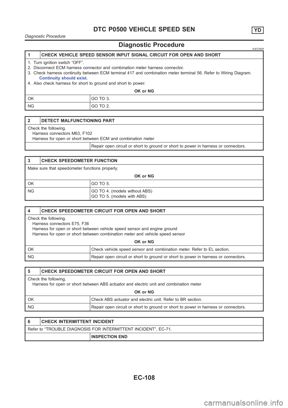
Diagnostic ProcedureNJEC0659
1 CHECK VEHICLE SPEED SENSOR INPUT SIGNAL CIRCUIT FOR OPEN AND SHORT
1. Turn ignition switch “OFF”.
2. Disconnect ECM harness connector and combination meter harness connector.
3. Check harness continuity between ECM terminal 417 and combination meter terminal 56. Refer to Wiring Diagram.
Continuity should exist.
4. Also check harness for short to ground and short to power.
OK or NG
OK GO TO 3.
NG GO TO 2.
2 DETECT MALFUNCTIONING PART
Check the following.
Harness connectors M63, F102
Harness for open or short between ECM and combination meter
Repair open circuit or short to ground or short to power in harness or connectors.
3 CHECK SPEEDOMETER FUNCTION
Make sure that speedometer functions properly.
OK or NG
OK GO TO 5.
NG GO TO 4. (models without ABS)
GO TO 5. (models with ABS)
4 CHECK SPEEDOMETER CIRCUIT FOR OPEN AND SHORT
Check the following.
Harness connectors E75, F36
Harness for open or short between vehicle speed sensor and engine ground
Harness for open or short between combination meter and vehicle speed sensor
OK or NG
OK Check vehicle speed sensor and combination meter. Refer to EL section.
NG Repair open circuit or short to ground or short to power in harness or connectors.
5 CHECK SPEEDOMETER CIRCUIT FOR OPEN AND SHORT
Check the following.
Harness for open or short between ABS actuator and electric unit and combination meter
OK or NG
OK Check ABS actuator and electric unit. Refer to BR section.
NG Repair open circuit or short to ground or short to power in harness or connectors.
6 CHECK INTERMITTENT INCIDENT
Refer to “TROUBLE DIAGNOSIS FOR INTERMITTENT INCIDENT”, EC-71.
INSPECTION END
DTC P0500 VEHICLE SPEED SENYD
Diagnostic Procedure
EC-108
Page 1170 of 3189
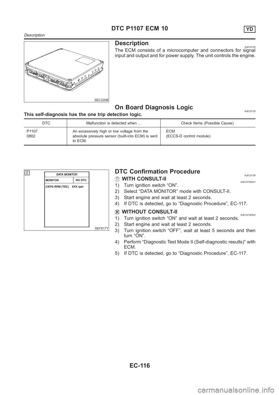
SEC220B
DescriptionNJEC0734The ECM consists of a microcomputer and connectors for signal
input and output and for power supply. The unit controls the engine.
On Board Diagnosis LogicNJEC0735This self-diagnosis has the one trip detection logic.
DTC Malfunction is detected when ... Check Items (Possible Cause)
P1107
0802An excessively high or low voltage from the
absolute pressure sensor (built-into ECM) is sent
to ECM.ECM
(ECCS-D control module)
SEF817Y
DTC Confirmation ProcedureNJEC0736WITH CONSULT-IINJEC0736S011) Turn ignition switch “ON”.
2) Select “DATA MONITOR” mode with CONSULT-II.
3) Start engine and wait at least 2 seconds.
4) If DTC is detected, go to “Diagnostic Procedure”, EC-117.
WITHOUT CONSULT-IINJEC0736S021) Turn ignition switch “ON” and wait at least 2 seconds.
2) Start engine and wait at least 2 seconds.
3) Turn ignition switch “OFF”, wait at least 5 seconds and then
turn “ON”.
4) Perform “Diagnostic Test Mode II (Self-diagnostic results)” with
ECM.
5) If DTC is detected, go to “Diagnostic Procedure”, EC-117.
DTC P1107 ECM 10YD
Description
EC-116
Page 1287 of 3189
JFE613A
SFE600A
SFE601A
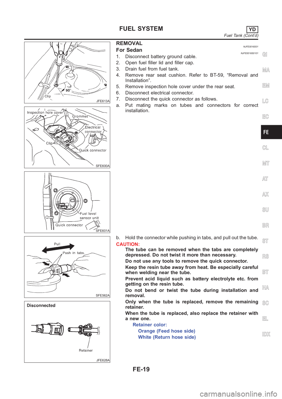
REMOVALNJFE0016S01For SedanNJFE0016S01011. Disconnect battery ground cable.
2. Open fuel filler lid and filler cap.
3. Drain fuel from fuel tank.
4. Remove rear seat cushion. Refer to BT-59, “Removal and
Installation”.
5. Remove inspection hole cover under the rear seat.
6. Disconnect electrical connector.
7. Disconnect the quick connector as follows.
a. Put mating marks on tubes and connectors for correct
installation.
SFE562A
JFE628A
b. Hold the connector while pushing in tabs, and pull out the tube.
CAUTION:
The tube can be removed when the tabs are completely
depressed. Do not twist it more than necessary.
Do not use any tools to remove the quick connector.
Keep the resin tube away from heat. Be especially careful
when welding near the tube.
Prevent acid liquid such as battery electrolyte etc. from
getting on the resin tube.
Do not bend or twist the tube during installation and
removal.
Only when the tube is replaced, remove the remaining
retainer.
When the tube is replaced, also replace the retainer with
a new one.
Retainer color:
Orange (Feed hose side)
White (Return hose side)
GI
MA
EM
LC
EC
CL
MT
AT
AX
SU
BR
ST
RS
BT
HA
SC
EL
IDX
FUEL SYSTEMYD
Fuel Tank (Cont’d)
FE-19
Page 1289 of 3189
JFE613A
SFE639A
SFE640A
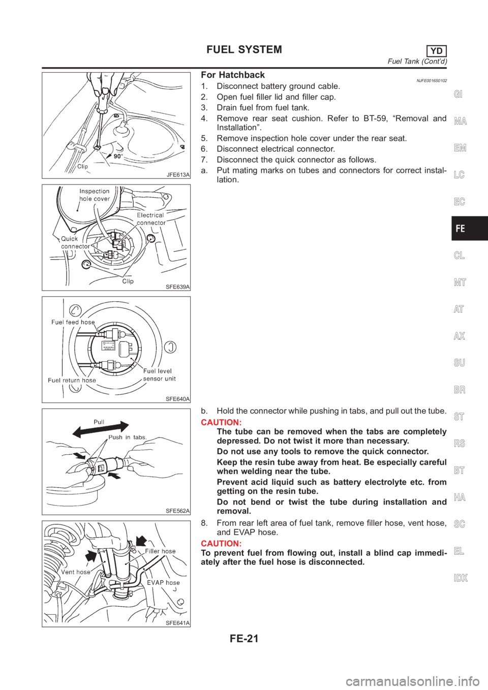
For HatchbackNJFE0016S01021. Disconnect battery ground cable.
2. Open fuel filler lid and filler cap.
3. Drain fuel from fuel tank.
4. Remove rear seat cushion. Refer to BT-59, “Removal and
Installation”.
5. Remove inspection hole cover under the rear seat.
6. Disconnect electrical connector.
7. Disconnect the quick connector as follows.
a. Put mating marks on tubes and connectors for correct instal-
lation.
SFE562A
b. Hold the connector while pushing in tabs, and pull out the tube.
CAUTION:
The tube can be removed when the tabs are completely
depressed. Do not twist it more than necessary.
Do not use any tools to remove the quick connector.
Keep the resin tube away from heat. Be especially careful
when welding near the tube.
Prevent acid liquid such as battery electrolyte etc. from
getting on the resin tube.
Do not bend or twist the tube during installation and
removal.
SFE641A
8. From rear left area of fuel tank, remove filler hose, vent hose,
and EVAP hose.
CAUTION:
To prevent fuel from flowing out, install a blind cap immedi-
ately after the fuel hose is disconnected.
GI
MA
EM
LC
EC
CL
MT
AT
AX
SU
BR
ST
RS
BT
HA
SC
EL
IDX
FUEL SYSTEMYD
Fuel Tank (Cont’d)
FE-21
Page 1300 of 3189
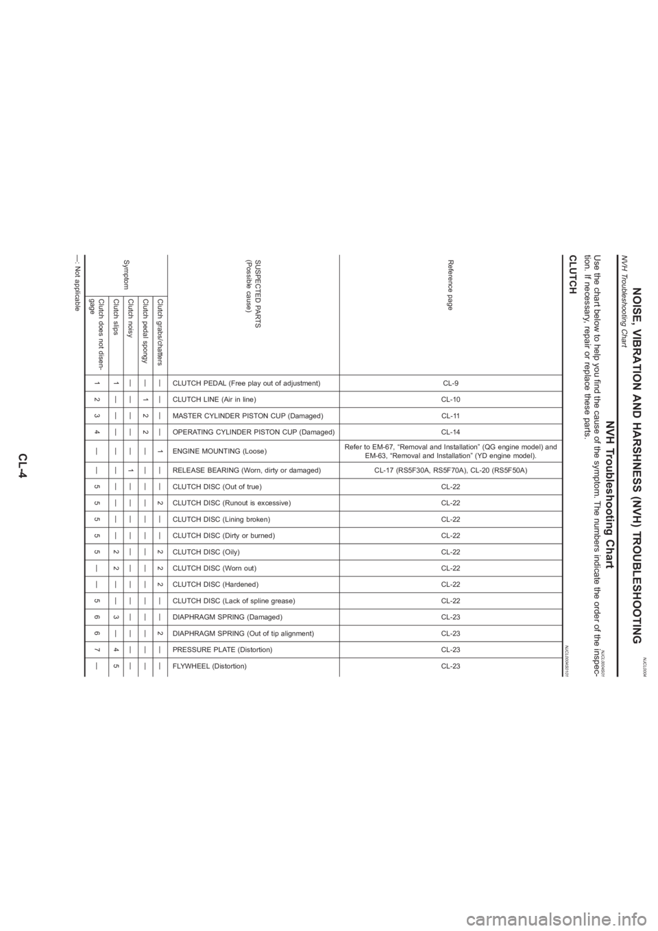
NJCL0004
NVH Troubleshooting Chart
NJCL0004S01
Use the chart below to help you find the cause of the symptom. The numbers indicate the order of the inspec-
tion. If necessary, repair or replace these parts.CLUTCH
NJCL0004S0101
Reference page
CL-9
CL-10
CL-11
CL-14
Refer to EM-67, “Removal and Installation” (QG engine model) and
EM-63, “Removal and Installation” (YD engine model).
CL-17 (RS5F30A, RS5F70A), CL-20 (RS5F50A)
CL-22
CL-22
CL-22
CL-22
CL-22
CL-22
CL-22
CL-22
CL-23
CL-23
CL-23
CL-23
SUSPECTED PARTS
(Possible cause)
CLUTCH PEDAL (Free play out of adjustment)
CLUTCH LINE (Air in line)
MASTER CYLINDER PISTON CUP (Damaged)
OPERATING CYLINDER PISTON CUP (Damaged)
ENGINE MOUNTING (Loose)
RELEASE BEARING (Worn, dirty or damaged)
CLUTCH DISC (Out of true)
CLUTCH DISC (Runout is excessive)
CLUTCH DISC (Lining broken)
CLUTCH DISC (Dirty or burned)
CLUTCH DISC (Oily)
CLUTCH DISC (Worn out)
CLUTCH DISC (Hardened)
CLUTCH DISC (Lack of spline grease)
DIAPHRAGM SPRING (Damaged)
DIAPHRAGM SPRING (Out of tip alignment)
PRESSURE PLATE (Distortion)
FLYWHEEL (Distortion)
SymptomClutch grabs/chatters———— 1 —— 2 —— 2 2 2 —— 2 ——
Clutch pedal spongy — 1 2 2 ——————————————
Clutch noisy———— — 1 ————————————
Clutch slips 1 — — — —————— 2 2 —— 3 — 4 5
Clutch does not disen-
gage1234 ——55555——5667—
—: Not applicable
NOISE, VIBRATION AND HARSHNESS (NVH) TROUBLESHOOTING
NVH Troubleshooting Chart
CL-4
Page 1565 of 3189
![NISSAN ALMERA N16 2003 Electronic User Guide CAN COMMUNICATION
AT-109
[EURO-OBD]
D
E
F
G
H
I
J
K
L
MA
B
AT
CAN COMMUNICATIONPFP:23710
System DescriptionECS007O2
CAN (Controller Area Network) is a serial communication line for real time applicati NISSAN ALMERA N16 2003 Electronic User Guide CAN COMMUNICATION
AT-109
[EURO-OBD]
D
E
F
G
H
I
J
K
L
MA
B
AT
CAN COMMUNICATIONPFP:23710
System DescriptionECS007O2
CAN (Controller Area Network) is a serial communication line for real time applicati](/img/5/57350/w960_57350-1564.png)
CAN COMMUNICATION
AT-109
[EURO-OBD]
D
E
F
G
H
I
J
K
L
MA
B
AT
CAN COMMUNICATIONPFP:23710
System DescriptionECS007O2
CAN (Controller Area Network) is a serial communication line for real time application. It is an on-vehicle mul-
tiplex communication line with high data communication speed and excellent error detection ability. Many elec-
tronic control units are equipped onto a vehicle, and each control unit shares information and links with other
control units during operation (not independent). In CAN communication, control units are connected with 2
communication lines (CAN H line, CAN L line) allowing a high rate of information transmission with less wiring.
Each control unit transmits/receives data but selectively reads required data only.
CAN Communication UnitECS007O3
×:Applicable
TYPE1
System diagram
Input/output signal chart
T: Transmit R: Receive Body type Sedan/ 5DH/B/ 3DH/B
Axle2WD
Engine QG18DE QG15DE/QG18DE
Transmission A/T M/T
Brake controlABS
CAN communication unit
ECM××
TCM×
Smart entrance control unit××
Data link connector××
Combination meter××
CAN communication type AT-109, "
TYPE1"AT-110, "TYPE 2"
SEL825Y
Signals ECM TCMSmart entrance
control unitCombination meter
Engine speed signal T R
Brake switch signal R T
Rear window defogger signal R T
Heater fan switch signal R T
Air conditioner switch signal R T
MI signal T R
Current gear position signal T R
Engine coolant temperature signal T R
Fuel consumption signal T R
Page 1761 of 3189
![NISSAN ALMERA N16 2003 Electronic User Guide CAN COMMUNICATION
AT-305
[EXC.F/EURO-OBD]
D
E
F
G
H
I
J
K
L
MA
B
AT
CAN COMMUNICATIONPFP:23710
System DescriptionECS007QX
CAN (Controller Area Network) is a serial communication line for real time app NISSAN ALMERA N16 2003 Electronic User Guide CAN COMMUNICATION
AT-305
[EXC.F/EURO-OBD]
D
E
F
G
H
I
J
K
L
MA
B
AT
CAN COMMUNICATIONPFP:23710
System DescriptionECS007QX
CAN (Controller Area Network) is a serial communication line for real time app](/img/5/57350/w960_57350-1760.png)
CAN COMMUNICATION
AT-305
[EXC.F/EURO-OBD]
D
E
F
G
H
I
J
K
L
MA
B
AT
CAN COMMUNICATIONPFP:23710
System DescriptionECS007QX
CAN (Controller Area Network) is a serial communication line for real time application. It is an on-vehicle mul-
tiplex communication line with high data communication speed and excellent error detection ability. Many elec-
tronic control units are equipped onto a vehicle, and each control unit shares information and links with other
control units during operation (not independent). In CAN communication, control units are connected with 2
communication lines (CAN H line, CAN L line) allowing a high rate of information transmission with less wiring.
Each control unit transmits/receives data but selectively reads required data only.
CAN Communication UnitECS007QY
×:Applicable
TYPE 1
System diagram
Input/output signal chart
T: Transmit R: Receive Body type Sedan/ 5DH/B/ 3DH/B
Axle2WD
Engine QG18DE QG15DE/QG18DE
Transmission A/T M/T
Brake controlABS
CAN communication unit
ECM××
TCM×
Smart entrance control unit××
Data link connector××
Combination meter××
CAN communication type AT-305, "
TYPE 1"AT- 3 0 6 , "TYPE 2"
SEL825Y
Signals ECM TCMSmart entrance
control unitCombination meter
Engine speed signal T R
Brake switch signal R T
Rear window defogger signal R T
Heater fan switch signal R T
Air conditioner switch signal R T
MI signal T R
Current gear position signal T R
Engine coolant temperature signal T R
Fuel consumption signal T R
Page 1860 of 3189
![NISSAN ALMERA N16 2003 Electronic User Guide AT-404
[ALL]
KEY INTERLOCK CABLE
KEY INTERLOCK CABLE
PFP:34908
ComponentsECS007SW
CAUTION:
●Install key interlock cable in such a way that it will not be damaged by sharp bends, twists or inter-
fer NISSAN ALMERA N16 2003 Electronic User Guide AT-404
[ALL]
KEY INTERLOCK CABLE
KEY INTERLOCK CABLE
PFP:34908
ComponentsECS007SW
CAUTION:
●Install key interlock cable in such a way that it will not be damaged by sharp bends, twists or inter-
fer](/img/5/57350/w960_57350-1859.png)
AT-404
[ALL]
KEY INTERLOCK CABLE
KEY INTERLOCK CABLE
PFP:34908
ComponentsECS007SW
CAUTION:
●Install key interlock cable in such a way that it will not be damaged by sharp bends, twists or inter-
ference with adjacent parts.
●After installing key interlock cable to control device, make sure that casing cap and bracket are
firmly secured in their positions.
RemovalECS007SX
1. Unlock slider by squeezing lock tabs on slider from adjuster
holder and remove interlock rod from cable.
SAT996J
SAT853J
Page 1984 of 3189
ATC-4
PRECAUTIONS
PRECAUTIONS
PFP:00001
Precautions for Supplemental Restraint System (SRS) “AIR BAG” and “SEAT
BELT PRE-TENSIONER”
EJS001YP
The Supplemental Restraint System such as “AIR BAG” and “SEAT BELT PRE-TENSIONER”, used along
with a front seat belt, helps to reduce the risk or severity of injury to the driver and front passenger for certain
types of collision. Information necessary to service the system safely is included in the SRS and SB section of
this Service Manual.
WARNING:
●To avoid rendering the SRS inoperative, which could increase the risk of personal injury or death
in the event of a collision which would result in air bag inflation, all maintenance must be per-
formed by an authorized NISSAN/INFINITI dealer.
●Improper maintenance, including incorrect removal and installation of the SRS, can lead to per-
sonal injury caused by unintentional activation of the system. For removal of Spiral Cable and Air
Bag Module, see the SRS section.
●Do not use electrical test equipment on any circuit related to the SRS unless instructed to in this
Service Manual. SRS wiring harnesses can be identified by yellow and/or orange harness connec-
tors.
Precautions for Working with HFC-134a (R-134a)EJS001YQ
WARNING:
●Use only specified lubricant for the HFC-134a (R-134a) A/C system and HFC-134a (R-134a) compo-
nents. If lubricant other than that specified is used, compressor malfunction is likely to occur.
●The specified HFC-134a (R-134a) lubricant rapidly absorbs moisture from the atmosphere. The fol-
lowing handling precautions must be observed:
–When removing refrigerant components from a vehicle, immediately cap (seal) the component to
minimize the entry of moisture from the atmosphere.
–When installing refrigerant components to a vehicle, do not remove the caps (unseal) until just
before connecting the components. Connect all refrigerant loop components as quickly as possi-
ble to minimize the entry of moisture into system.
–Only use the specified lubricant from a sealed container. Immediately reseal containers of lubri-
cant. Without proper sealing, lubricant will become moisture saturated and should not be used.
–Avoid breathing A/C refrigerant and lubricant vapor or mist. Exposure may irritate eyes, nose and
throat. Remove HFC-134a (R-134a) from the A/C system, using certified service equipment meet-
ing requirements of SAE J2210 HFC-134a (R-134a) recycling equipment, or J2209 HFC-134a (R-
134a) recovery equipment. If accidental system discharge occurs, ventilate work area before
resuming service. Additional health and safety information may be obtained from refrigerant and
lubricant manufacturers.
–Do not allow lubricant (Nissan A/C System Oil Type S) to come in contact with styrofoam parts.
Damage may result.
General Refrigerant PrecautionsEJS001YR
WARNING:
●Do not release refrigerant into the air. Use approved recovery/recycling equipment to capture the
refrigerant every time an air conditioning system is discharged.
●Always wear eye and hand protection (goggles and gloves) when working with any refrigerant or
air conditioning system.
●Do not store or heat refrigerant containers above 52°C (125°F).
●Do not heat a refrigerant container with an open flame; if container warming is required, place the
bottom of the container in a warm pail of water.
●Do not intentionally drop, puncture, or incinerate refrigerant containers.
●Keep refrigerant away from open flames: poisonous gas will be produced if refrigerant burns.
●Refrigerant will displace oxygen, therefore be certain to work in well ventilated areas to prevent
suffocation.
●Do not pressure test or leak test HFC-134a (R-134a) service equipment and/or vehicle air condi-
tioning systems with compressed air during repair. Some mixtures of air and HFC-134a (R-134a)