OBD port NISSAN ALMERA N16 2003 Electronic Repair Manual
[x] Cancel search | Manufacturer: NISSAN, Model Year: 2003, Model line: ALMERA N16, Model: NISSAN ALMERA N16 2003Pages: 3189, PDF Size: 54.76 MB
Page 38 of 3189

NJGI0007
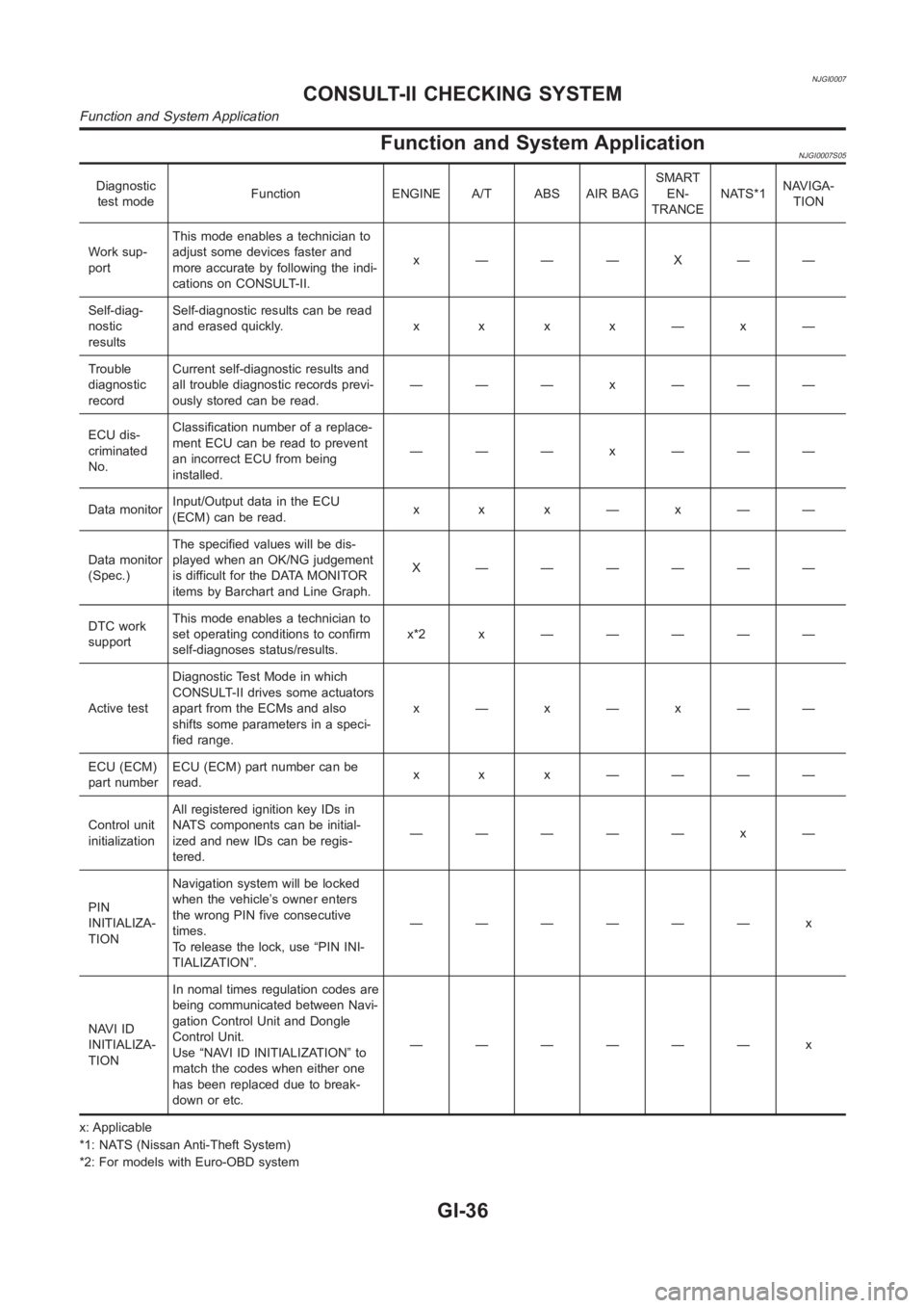
Function and System ApplicationNJGI0007S05
Diagnostic
test modeFunction ENGINE A/T ABS AIR BAGSMART
EN-
TRANCENATS*1NAVIGA-
TION
Work sup-
portThis mode enables a technician to
adjust some devices faster and
more accurate by following the indi-
cations on CONSULT-II.x ———X——
Self-diag-
nostic
resultsSelf-diagnostic results can be read
anderasedquickly. x x x x—x—
Trouble
diagnostic
recordCurrent self-diagnostic results and
all trouble diagnostic records previ-
ously stored can be read.——— x ———
ECU dis-
criminated
No.Classification number of a replace-
ment ECU can be read to prevent
an incorrect ECU from being
installed.——— x ———
Data monitorInput/Output data in the ECU
(ECM) can be read.x x x—x——
Data monitor
(Spec.)The specified values will be dis-
played when an OK/NG judgement
is difficult for the DATA MONITOR
items by Barchart and Line Graph.X ——————
DTC work
supportThis mode enables a technician to
set operating conditions to confirm
self-diagnoses status/results.x*2x —————
Active testDiagnostic Test Mode in which
CONSULT-II drives some actuators
apart from the ECMs and also
shifts some parameters in a speci-
fied range.x—x—x——
ECU (ECM)
part numberECU (ECM) part number can be
read.x x x ————
Control unit
initializationAll registered ignition key IDs in
NATS components can be initial-
ized and new IDs can be regis-
tered.————— x —
PIN
INITIALIZA-
TIONNavigation system will be locked
when the vehicle’s owner enters
the wrong PIN five consecutive
times.
To release the lock, use “PIN INI-
TIALIZATION”.—————— x
NAVI ID
INITIALIZA-
TIONIn nomal times regulation codes are
being communicated between Navi-
gation Control Unit and Dongle
Control Unit.
Use “NAVI ID INITIALIZATION” to
match the codes when either one
has been replaced due to break-
down or etc.—————— x
x: Applicable
*1: NATS (Nissan Anti-Theft System)
*2: For models with Euro-OBD system
CONSULT-II CHECKING SYSTEM
Function and System Application
GI-36
Page 55 of 3189

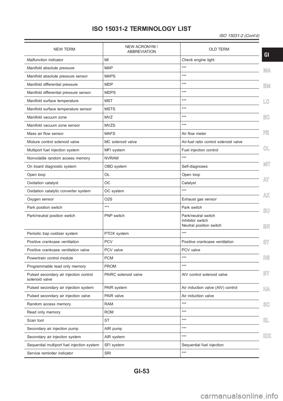
NEW TERMNEW ACRONYM /
ABBREVIATIONOLD TERM
Malfunction indicator MI Check engine light
Manifold absolute pressure MAP ***
Manifold absolute pressure sensor MAPS ***
Manifold differential pressure MDP ***
Manifold differential pressure sensor MDPS ***
Manifold surface temperature MST ***
Manifold surface temperature sensor MSTS ***
Manifold vacuum zone MVZ ***
Manifold vacuum zone sensor MVZS ***
Mass air flow sensor MAFS Air flow meter
Mixture control solenoid valve MC solenoid valve Air-fuel ratio control solenoid valve
Multiport fuel injection system MFI system Fuel injection control
Nonvolatile random access memory NVRAM ***
On board diagnostic system OBD system Self-diagnoses
Open loop OL Open loop
Oxidation catalyst OC Catalyst
Oxidation catalytic converter system OC system ***
Oxygen sensor O2S Exhaust gas sensor
Park position switch *** Park switch
Park/neutral position switch PNP switch Park/neutral switch
Inhibitor switch
Neutral position switch
Periodic trap oxidizer system PTOX system ***
Positive crankcase ventilation PCV Positive crankcase ventilation
Positive crankcase ventilation valve PCV valve PCV valve
Powertrain control module PCM ***
Programmable read only memory PROM ***
Pulsed secondary air injection control
solenoid valvePAIRC solenoid valve AIV control solenoid valve
Pulsed secondary air injection system PAIR system Air induction valve (AIV) control
Pulsed secondary air injection valve PAIR valve Air induction valve
Random access memory RAM ***
Read only memory ROM ***
Scan tool ST ***
Secondary air injection pump AIR pump ***
Secondary air injection system AIR system ***
Sequential multiport fuel injection system SFI system Sequential fuel injection
Service reminder indicator SRI ***
MA
EM
LC
EC
FE
CL
MT
AT
AX
SU
BR
ST
RS
BT
HA
SC
EL
IDX
ISO 15031-2 TERMINOLOGY LIST
ISO 15031-2 (Cont’d)
GI-53
Page 94 of 3189
![NISSAN ALMERA N16 2003 Electronic Repair Manual EM-16
[QG]
INTAKE MANIFOLD
INTAKE MANIFOLD
PFP:14003
Removal and InstallationEBS00LQ3
REMOVAL
WARNING:
To avoid the danger of being scalded, never drain the coolant when the engine is hot.
1. Release NISSAN ALMERA N16 2003 Electronic Repair Manual EM-16
[QG]
INTAKE MANIFOLD
INTAKE MANIFOLD
PFP:14003
Removal and InstallationEBS00LQ3
REMOVAL
WARNING:
To avoid the danger of being scalded, never drain the coolant when the engine is hot.
1. Release](/img/5/57350/w960_57350-93.png)
EM-16
[QG]
INTAKE MANIFOLD
INTAKE MANIFOLD
PFP:14003
Removal and InstallationEBS00LQ3
REMOVAL
WARNING:
To avoid the danger of being scalded, never drain the coolant when the engine is hot.
1. Release fuel pressure.
Refer to EC-34, "
FUEL PRESSURE RELEASE" (WITH EURO-OBD), EC-427, "FUEL PRESSURE
RELEASE" (WITHOUT EURO-OBD).
2. Remove air duct and air cleaner case.
Refer to EM-14, "
Removal and Installation" .
3. Disconnect harness on engine top surface, and move it aside.
4. Disconnect fuel injector/fuel tube assembly from intake manifold, and move it aside.
●It is not necessary to disconnect fuel hose.
5. Disconnect the following vacuum hoses.
6. Disconnect blow-by hose (between intake manifold collector and rocker cover).
KBIA1363E
1. Electric throttle control actuator 2. Gasket 3. Intake manifold collector
4.EVAP canister purge volume control
solenoid valve5. Vacuum hose 6. Vacuum hose
7. Hose clamp 8. Intake manifold support (front) 9. Harness bracket
10. Vacuum hose 11. Intake manifold 12. PCV hose
13. Gasket 14. Vacuum hose 15. Gasket
16. Intake manifold support (rear) 17. Harness bracket 18. Intake manifold support (engine rear)
19. Grounding wire
Page 146 of 3189
![NISSAN ALMERA N16 2003 Electronic Repair Manual EM-68
[QG]
ENGINE ASSEMBLY
WARNING:
●Position vehicle on a flat and solid surface.
●Place chocks at front and back of rear wheels.
●Do not remove engine until exhaust system has complete NISSAN ALMERA N16 2003 Electronic Repair Manual EM-68
[QG]
ENGINE ASSEMBLY
WARNING:
●Position vehicle on a flat and solid surface.
●Place chocks at front and back of rear wheels.
●Do not remove engine until exhaust system has complete](/img/5/57350/w960_57350-145.png)
EM-68
[QG]
ENGINE ASSEMBLY
WARNING:
●Position vehicle on a flat and solid surface.
●Place chocks at front and back of rear wheels.
●Do not remove engine until exhaust system has completely cooled off, otherwise, you may burn
yourself and/or fire may break out in fuel line.
●Before disconnecting fuel hose, release pressure.
Refer to EC-34 (WITH EURO-OBD), EC-428 (WITHOUT EURO-OBD).
●Be sure to lift engine and transaxle in a safe manner.
●For engines not equipped with engine slingers, attach proper slingers and bolts described in
PARTS CATALOG.
CAUTION:
●When lifting engine, be sure to clear surrounding parts. Use special care near accelerator wire
casing, brake lines and brake master cylinder.
●When lifting the engine, always use engine slingers in a safe manner.
●When removing drive shaft, be careful not to damage grease seal of transaxle.
●Before separating engine and transaxle, remove crankshaft position sensor (POS) from the cylin-
der block assembly.
●Always be extra careful not to damage edge of crankshaft position sensor (POS), or signal plate
teeth.
Engine cannot be removed separately from transaxle. Remove engine with transaxle as an assembly.
REMOVAL
1. Drain coolant from radiator and cylinder block. Refer to LC-17, "Chacking Engine Coolant".
2. Remove coolant reservoir tank and bracket.
3. Drain engine oil.
4. Remove battery and battery tray.
5. Remove air cleaner and air duct.
6. Remove drive belts.
7. Remove alternator and air conditioner compressor from engine.
8. Remove power steering oil pump from engine and position aside.
Power steering oil pump does not need to be disconnected from power steering tubes.
9. Remove the following parts:
●RH and LH front tires
●Splash covers
●RH and LH brake caliper assemblies
Refer to BR-28,"Removal".
Brake hose does not need to be disconnected from brake
caliper assembly. Never depress brake pedal.
●RH & LH drive shaft. Refer to AX-11, "Removal".
When removing drive shaft, be careful not to damage
transaxle side grease seal.
●Disconnect control rod and support rod from transaxle. (M/T
models.)
Refer to MT-26, "Removal".
●Disconnect control cable from transaxle. (A/T models.)
Refer to AT-411, "Removal".
SEM174D
SEM109G
Page 331 of 3189

EC-1
ENGINE CONTROL SYSTEM
B ENGINE
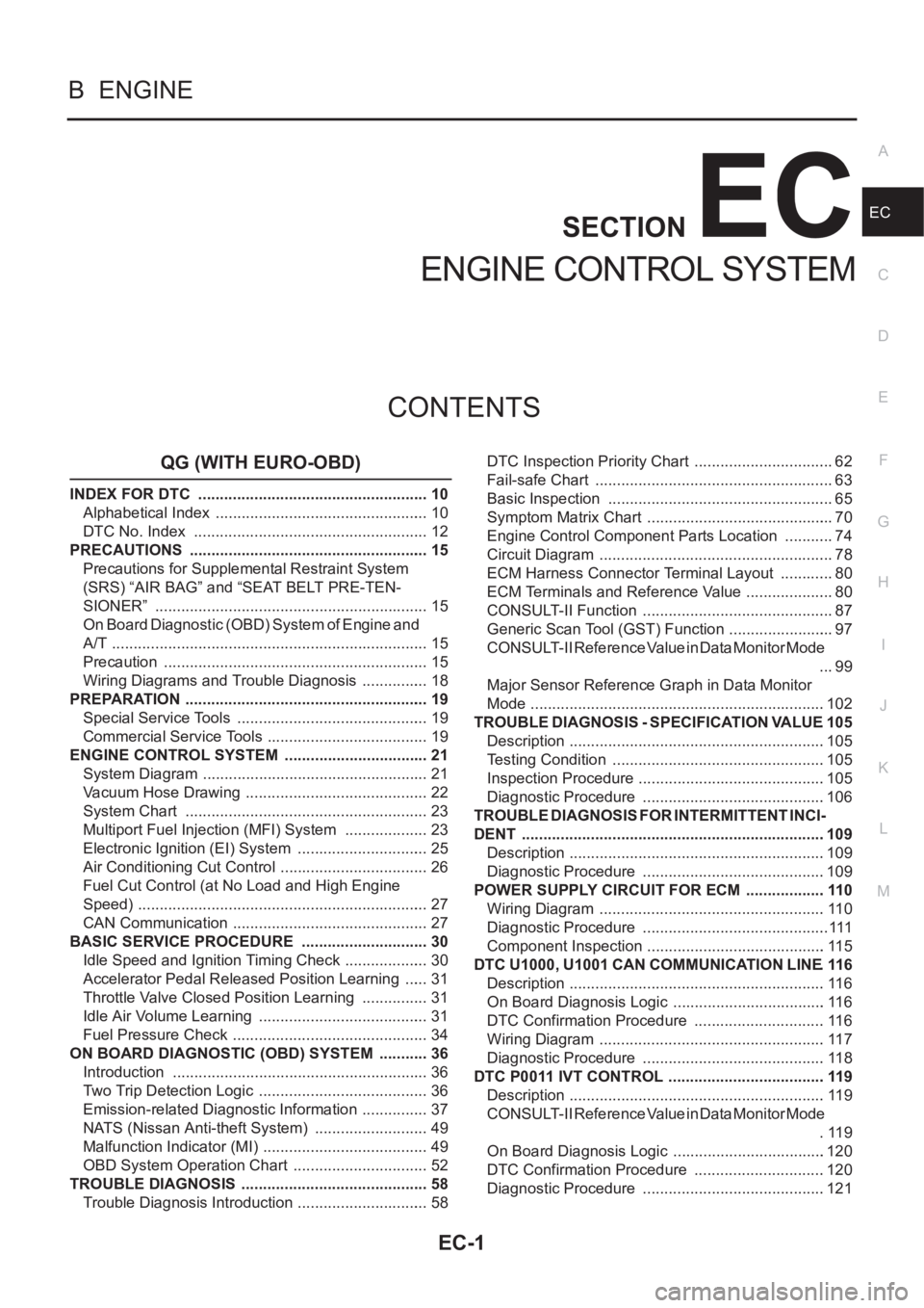
CONTENTS
C
D
E
F
G
H
I
J
K
L
M
SECTION
A
EC
ENGINE CONTROL SYSTEM
QG (WITH EURO-OBD)
INDEX FOR DTC ...................................................... 10
Alphabetical Index .................................................. 10
DTC No. Index ....................................................... 12
PRECAUTIONS ........................................................ 15
Precautions for Supplemental Restraint System
(SRS) “AIR BAG” and “SEAT BELT PRE-TEN-
SIONER” ................................................................ 15
On Board Diagnostic (OBD) System of Engine and
A/T .......................................................................... 15
Precaution .............................................................. 15
Wiring Diagrams and Trouble Diagnosis ................ 18
PREPARATION ......................................................... 19
Special Service Tools ............................................. 19
Commercial Service Tools ...................................... 19
ENGINE CONTROL SYSTEM .................................. 21
System Diagram ..................................................... 21
Vacuum Hose Drawing ........................................... 22
System Chart ......................................................... 23
Multiport Fuel Injection (MFI) System .................... 23
Electronic Ignition (EI) System ............................... 25
Air Conditioning Cut Control ................................... 26
Fuel Cut Control (at No Load and High Engine
Speed) .................................................................... 27
CAN Communication .............................................. 27
BASIC SERVICE PROCEDURE .............................. 30
Idle Speed and Ignition Timing Check .................... 30
Accelerator Pedal Released Position Learning ...... 31
Throttle Valve Closed Position Learning ................ 31
Idle Air Volume Learning ........................................ 31
Fuel Pressure Check .............................................. 34
ON BOARD DIAGNOSTIC (OBD) SYSTEM ............ 36
Introduction ............................................................ 36
Two Trip Detection Logic ........................................ 36
Emission-related Diagnostic Information ................ 37
NATS (Nissan Anti-theft System) ........................... 49
Malfunction Indicator (MI) ....................................... 49
OBD System Operation Chart ................................ 52
TROUBLE DIAGNOSIS ............................................ 58
Trouble Diagnosis Introduction ............................... 58DTC Inspection Priority Chart ................................. 62
Fail-safe Chart ........................................................ 63
Basic Inspection ..................................................... 65
Symptom Matrix Chart ............................................ 70
Engine Control Component Parts Location ............ 74
Circuit Diagram ....................................................... 78
ECM Harness Connector Terminal Layout ............. 80
ECM Terminals and Reference Value ..................
... 80
CONSULT-II Function ............................................. 87
Generic Scan Tool (GST) Function ......................... 97
CONSULT-II Reference Value in Data Monitor Mode
... 99
Major Sensor Reference Graph in Data Monitor
Mode .....................................................................102
TROUBLE DIAGNOSIS - SPECIFICATION VALUE .105
Description ............................................................105
Testing Condition ..................................................105
Inspection Procedure ............................................105
Diagnostic Procedure ...........................................106
TROUBLE DIAGNOSIS FOR INTERMITTENT INCI-
DENT .......................................................................109
Description ............................................................109
Diagnostic Procedure ...........................................109
POWER SUPPLY CIRCUIT FOR ECM ...................110
Wiring Diagram .....................................................110
Diagnostic Procedure ............................................111
Component Inspection ..........................................115
DTC U1000, U1001 CAN COMMUNICATION LINE .116
Description ............................................................116
On Board Diagnosis Logic ....................................116
DTC Confirmation Procedure ...............................116
Wiring Diagram .....................................................117
Diagnostic Procedure ...........................................118
DTC P0011 IVT CONTROL .....................................119
Description ............................................................119
CONSULT-II Reference Value in Data Monitor Mode
.119
On Board Diagnosis Logic ....................................120
DTC Confirmation Procedure ...............................120
Diagnostic Procedure ...........................................121
Page 335 of 3189

EC-5
C
D
E
F
G
H
I
J
K
L
M
ECA Wiring Diagram .................................................... 353
Diagnostic Procedure ........................................... 354
DTC P1706 PNP SWITCH ...................................... 356
Component Description ........................................ 356
CONSULT-II Reference Value in Data Monitor Mode
. 356
On Board Diagnosis Logic ................................... 356
DTC Confirmation Procedure ............................... 356
Overall Function Check ........................................ 357
Wiring Diagram .................................................... 358
Diagnostic Procedure ........................................... 359
DTC P1805 BRAKE SWITCH ................................ 360
Description ........................................................... 360
CONSULT-II Reference Value in Data Monitor Mode
. 360
On Board Diagnosis Logic ................................... 360
DTC Confirmation Procedure ............................... 360
Wiring Diagram .................................................... 361
Diagnostic Procedure ........................................... 362
Component Inspection ......................................... 364
IGNITION SIGNAL .................................................. 365
Component Description ........................................ 365
Wiring Diagram .................................................... 366
Diagnostic Procedure ........................................... 369
Component Inspection ......................................... 373
Removal and Installation ...................................... 374
INJECTOR CIRCUIT ............................................... 375
Component Description ........................................ 375
CONSULT-II Reference Value in Data Monitor Mode
. 375
Wiring Diagram .................................................... 376
Diagnostic Procedure ........................................... 377
Component Inspection ......................................... 380
Removal and Installation ...................................... 380
FUEL PUMP CIRCUIT ............................................ 381
Description ........................................................... 381
CONSULT-II Reference Value in Data Monitor Mode
. 381
Wiring Diagram .................................................... 382
Diagnostic Procedure ........................................... 383
Component Inspection ......................................... 385
Removal and Installation ...................................... 386
REFRIGERANT PRESSURE SENSOR ................. 387
Component Description ........................................ 387
Wiring Diagram .................................................... 388
Diagnostic Procedure ........................................... 389
Removal and Installation ...................................... 391
ELECTRICAL LOAD SIGNAL ................................ 392
Description ...................................................
........ 392
CONSULT-II Reference Value in Data Monitor Mode
. 392
Wiring Diagram .................................................... 393
Diagnostic Procedure ........................................... 394
MI & DATA LINK CONNECTORS .......................... 397
Wiring Diagram—LHD Models ............................. 397
Wiring Diagram—RHD Models ............................ 398
EVAPORATIVE EMISSION SYSTEM ..................... 399
Description ........................................................... 399
Component Inspection ......................................... 401POSITIVE CRANKCASE VENTILATION ...............402
Description ............................................................402
Component Inspection ..........................................402
SERVICE DATA AND SPECIFICATIONS (SDS) ....404
Fuel Pressure .......................................................404
Idle Speed and Ignition Timing .............................404
Calculated Load Value ..........................................404
Mass Air Flow Sensor ...........................................404
Intake Air Temperature Sensor .............................404
Engine Coolant Temperature Sensor ...................404
Heated Oxygen Sensor 1 Heater .........................404
Heated Oxygen sensor 2 Heater ..........................404
Crankshaft Position Sensor (POS) .......................404
Camshaft Position Sensor (PHASE) ....................404
Throttle Control Motor ...........................................405
Injector ..................................................................405
Fuel Pump ............................................................405
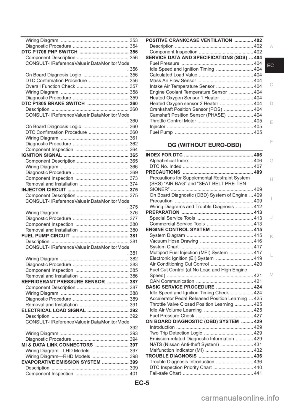
QG (WITHOUT EURO-OBD)
INDEX FOR DTC .....................................................406
Alphabetical Index ................................................406
DTC No. Index ......................................................407
PRECAUTIONS ......................................................409
Precautions for Supplemental Restraint System
(SRS) “AIR BAG” and “SEAT BELT PRE-TEN-
SIONER” ...............................................................409
On Board Diagnostic (OBD) System of Engine ....409
Precaution ............................................................409
Wiring Diagrams and Trouble Diagnosis ..............412
PREPARATION .......................................................413
Special Service Tools ...........................................413
Commercial Service Tools ....................................413
ENGINE CONTROL SYSTEM ................................415
System Diagram ...................................................415
Vacuum Hose Drawing .........................................416
System Chart ........................................................417
Multiport Fuel Injection (MFI) System ...................417
Electronic Ignition (EI) System .............................419
Air Conditioning Cut Control .................................420
Fuel Cut Control (at No Load and High Engine
Speed) ..................................................................421
CAN Communication ............................................421
BASIC SERVICE PROCEDURE .............................424
Idle Speed and Ignition Timing Check ..................424
Accelerator Pedal Released Position Learning ....425
Throttle Valve Closed Position Learning ...............425
Idle Air Volume Learning ......................................425
Fuel Pressure Check ............................................427
ON BOARD DIAGNOSTIC (OBD) SYSTEM ..........429
Introduction ...........................................................429
Two Trip Detection Logic ......................................429
Emission-related Diagnostic Information ..............429
NATS (Nissan Anti-theft System) .........................431
Malfunction Indicator (MI) .....................................432
TROUBLE DIAGNOSIS ..........................................436
Trouble Diagnosis Introduction .............................436
DTC Inspection Priority Chart ...............................440
Fail-safe Chart ......................................................441
Page 353 of 3189
![NISSAN ALMERA N16 2003 Electronic Repair Manual ENGINE CONTROL SYSTEM
EC-23
[QG (WITH EURO-OBD)]
C
D
E
F
G
H
I
J
K
L
MA
EC
System ChartEBS00K34
*1: This sensor is not used to control the engine system under normal conditions.
*2: The signals are se NISSAN ALMERA N16 2003 Electronic Repair Manual ENGINE CONTROL SYSTEM
EC-23
[QG (WITH EURO-OBD)]
C
D
E
F
G
H
I
J
K
L
MA
EC
System ChartEBS00K34
*1: This sensor is not used to control the engine system under normal conditions.
*2: The signals are se](/img/5/57350/w960_57350-352.png)
ENGINE CONTROL SYSTEM
EC-23
[QG (WITH EURO-OBD)]
C
D
E
F
G
H
I
J
K
L
MA
EC
System ChartEBS00K34
*1: This sensor is not used to control the engine system under normal conditions.
*2: The signals are sent to the ECM through CAN communication line.
*3: The output signals are sent from the ECM through CAN communication line.
Multiport Fuel Injection (MFI) SystemEBS00K35
INPUT/OUTPUT SIGNAL CHART
*1: Under normal conditions, this sensor is not for engine control operation.
*2: This signal is sent to the ECM through CAN communication line.
*3: ECM determines the start signal status by the signals of engine speed and battery voltage.
SYSTEM DESCRIPTION
The amount of fuel injected from the fuel injector is determined by the ECM. The ECM controls the length of
time the valve remains open (injection pulse duration). The amount of fuel injected is a program value in the
Input (Sensor) ECM Function Output (Actuator)
●Camshaft position sensor (PHASE)
●Crankshaft position sensor (POS)
●Mass air flow sensor
●Engine coolant temperature sensor
●Heated oxygen sensor 1
●Throttle position sensor
●Accelerator pedal position sensor
●Park/neutral position (PNP) switch
●Intake air temperature sensor
●Power steering pressure sensor
●Ignition switch
●Stop lamp switch
●Battery voltage
●Knock sensor
●Refrigerant pressure sensor
●Heated oxygen sensor 2*1
●TCM (Transmission control module)*2
●Air conditioner switch*2
●Vehicle speed signal*2
●Electrical load signal*2
Fuel injection & mixture ratio control Fuel injectors
Electronic ignition system Power transistor
Fuel pump control Fuel pump relay
On board diagnostic system
MI (On the instrument panel)
*3
Intake valve timing controlIntake valve timing control solenoid
valve
Heated oxygen sensor 1 heater control Heated oxygen sensor 1 heater
Heated oxygen sensor 2 heater control Heated oxygen sensor 2 heater
EVAP canister purge flow controlEVAP canister purge volume control
solenoid valve
Air conditioning cut control
Air conditioner relay
*3
Cooling fan control
Cooling fan relay*3
Sensor Input Signal to ECM ECM Function Actuator
Crankshaft position sensor (POS)
Camshaft position sensor (PHASE)Engine speed
*3 and piston position
Fuel injection & mixture
ratio controlFuel injectors Mass air flow sensor Amount of intake air
Engine coolant temperature sensor Engine coolant temperature
Heated oxygen sensor 1 Density of oxygen in exhaust gas
Throttle position sensor Throttle position
Accelerator pedal position sensor Accelerator pedal position
Park/neutral position (PNP) switch Gear position
Knock sensor Engine knocking condition
Battery
Battery voltage
*3
Power steering pressure sensor Power steering operation
Heated oxygen sensor 2
*1Density of oxygen in exhaust gas
Vehicle speed signal
*2Vehicle speed
Air conditioner switch
*2Air conditioner operation
Page 355 of 3189
![NISSAN ALMERA N16 2003 Electronic Repair Manual ENGINE CONTROL SYSTEM
EC-25
[QG (WITH EURO-OBD)]
C
D
E
F
G
H
I
J
K
L
MA
EC
inally designed. Both manufacturing differences (i.e., mass air flow sensor hot film) and characteristic changes
during opera NISSAN ALMERA N16 2003 Electronic Repair Manual ENGINE CONTROL SYSTEM
EC-25
[QG (WITH EURO-OBD)]
C
D
E
F
G
H
I
J
K
L
MA
EC
inally designed. Both manufacturing differences (i.e., mass air flow sensor hot film) and characteristic changes
during opera](/img/5/57350/w960_57350-354.png)
ENGINE CONTROL SYSTEM
EC-25
[QG (WITH EURO-OBD)]
C
D
E
F
G
H
I
J
K
L
MA
EC
inally designed. Both manufacturing differences (i.e., mass air flow sensor hot film) and characteristic changes
during operation (i.e., injector clogging) directly affect mixture ratio.
Accordingly, the difference between the basic and theoretical mixture ratios is monitored in this system. This is
then computed in terms of “injection pulse duration” to automatically compensate for the difference between
the two ratios.
“Fuel trim” refers to the feedback compensation value compared against the basic injection duration. Fuel trim
includes short term fuel trim and long term fuel trim.
“Short term fuel trim” is the short-term fuel compensation used to maintain the mixture ratio at its theoretical
value. The signal from heated oxygen sensor 1 indicates whether the mixture ratio is RICH or LEAN compared
to the theoretical value. The signal then triggers a reduction in fuel volume if the mixture ratio is rich, and an
increase in fuel volume if it is lean.
“Long term fuel trim” is overall fuel compensation carried out long-term to compensate for continual deviation
of the short term fuel trim from the central value. Such deviation will occur due to individual engine differences,
wear over time and changes in the usage environment.
FUEL INJECTION TIMING
Two types of systems are used.
Sequential Multiport Fuel Injection System
Fuel is injected into each cylinder during each engine cycle according to the firing order. This system is used
when the engine is running.
Simultaneous Multiport Fuel Injection System
Fuel is injected simultaneously into all four cylinders twice each engine cycle. In other words, pulse signals of
the same width are simultaneously transmitted from the ECM.
The four injectors will then receive the signals two times for each engine cycle.
This system is used when the engine is being started and/or if the fail-safe system (CPU) is operating.
FUEL SHUT-OFF
Fuel to each cylinder is cut off during deceleration or operation of the engine at excessively high speeds.
Electronic Ignition (EI) SystemEBS00K36
INPUT/OUTPUT SIGNAL CHART
*1: This signal is sent to the ECM through CAN communication line.
*2: ECM determines the start signal status by the signals of engine speed and battery voltage.
SEF337W
Sensor Input Signal to ECM ECM Function Actuator
Crankshaft position sensor (POS)
Camshaft position sensor (PHASE)Engine speed
*2 and piston position
Ignition timing control Power transistor Mass air flow sensor Amount of intake air
Engine coolant temperature sensor Engine coolant temperature
Throttle position sensor Throttle position
Accelerator pedal position sensor Accelerator pedal position
Knock sensor Engine knocking
Park/neutral position (PNP) switch Gear position
Battery
Battery voltage
*2
Vehicle speed signal*1Vehicle speed
Page 357 of 3189
![NISSAN ALMERA N16 2003 Electronic Repair Manual ENGINE CONTROL SYSTEM
EC-27
[QG (WITH EURO-OBD)]
C
D
E
F
G
H
I
J
K
L
MA
EC
Fuel Cut Control (at No Load and High Engine Speed)EBS00K38
INPUT/OUTPUT SIGNAL CHART
*1: This signal is sent to the ECM thro NISSAN ALMERA N16 2003 Electronic Repair Manual ENGINE CONTROL SYSTEM
EC-27
[QG (WITH EURO-OBD)]
C
D
E
F
G
H
I
J
K
L
MA
EC
Fuel Cut Control (at No Load and High Engine Speed)EBS00K38
INPUT/OUTPUT SIGNAL CHART
*1: This signal is sent to the ECM thro](/img/5/57350/w960_57350-356.png)
ENGINE CONTROL SYSTEM
EC-27
[QG (WITH EURO-OBD)]
C
D
E
F
G
H
I
J
K
L
MA
EC
Fuel Cut Control (at No Load and High Engine Speed)EBS00K38
INPUT/OUTPUT SIGNAL CHART
*1: This signal is sent to the ECM through CAN communication line.
SYSTEM DESCRIPTION
If the engine speed is above 3,950 rpm with no load (for example, in neutral and engine speed over 3,950
rpm) fuel will be cut off after some time. The exact time when the fuel is cut off varies based on engine speed.
Fuel cut will operate until the engine speed reaches 1,500 rpm, then fuel cut is cancelled.
NOTE:
This function is different from deceleration control listed under “Multiport Fuel Injection (MFI) System”, EC-23
.
CAN CommunicationEBS00K39
SYSTEM DESCRIPTION
CAN (Controller Area Network) is a serial communication line for real time application. It is an on-vehicle mul-
tiplex communication line with high data communication speed and excellent error detection ability. Many elec-
tronic control units are equipped onto a vehicle, and each control unit shares information and links with other
control units during operation (not independent). In CAN communication, control units are connected with 2
communication lines (CAN H line, CAN L line) allowing a high rate of information transmission with less wiring.
Each control unit transmits/receives data but selectively reads required data only.
CAN COMMUNICATION UNIT
×:ApplicableSensor Input Signal to ECM ECM Function Actuator
Park/neutral position (PNP) switch Neutral position
Fuel cut control Fuel injectors Throttle position sensor Throttle position
Accelerator pedal position sensor Accelerator pedal position
Engine coolant temperature sensor Engine coolant temperature
Crankshaft position sensor (POS)
Camshaft position sensor (PHASE)Engine speed
Vehicle speed signal
*1Vehicle speed
Body type Sedan/ 5DH/B/ 3DH/B
Axle2WD
Engine QG18DE QG15DE/QG18DE
Transmission A/T M/T
Brake controlABS
CAN communication unit
ECM××
TCM×
Smart entrance control unit××
Data link connector××
Combination meter××
CAN communication type EC-28, "
Type 1"EC-29, "Ty p e 2"
Page 362 of 3189
![NISSAN ALMERA N16 2003 Electronic Repair Manual EC-32
[QG (WITH EURO-OBD)]
BASIC SERVICE PROCEDURE
PREPARATION
Before performing “Idle Air Volume Learning”, make sure that all of the following conditions are satisfied.
Learning will be cancelle NISSAN ALMERA N16 2003 Electronic Repair Manual EC-32
[QG (WITH EURO-OBD)]
BASIC SERVICE PROCEDURE
PREPARATION
Before performing “Idle Air Volume Learning”, make sure that all of the following conditions are satisfied.
Learning will be cancelle](/img/5/57350/w960_57350-361.png)
EC-32
[QG (WITH EURO-OBD)]
BASIC SERVICE PROCEDURE
PREPARATION
Before performing “Idle Air Volume Learning”, make sure that all of the following conditions are satisfied.
Learning will be cancelled if any of the following conditions are missed for even a moment.
●Battery voltage: More than 12.9V (At idle)
●Engine coolant temperature: 70 - 95°C (158 - 203°F)
●PNP switch: ON
●Electric load switch: OFF
(Air conditioner, headlamp, rear window defogger)
On vehicles equipped with daytime light systems, set lighting switch to the 1st position to light
only small lamps.
●Steering wheel: Neutral (Straight-ahead position)
●Vehicle speed: Stopped
●Transmission: Warmed-up
For A/T models with CONSULT-II, drive vehicle until “FLUID TEMP SE” in “DATA MONITOR” mode of “A/
T” system indicates less than 0.9V.
For A/T models without CONSULT-II and M/T models, drive vehicle for 10 minutes.
OPERATION PROCEDURE
With CONSULT-II
1. Perform EC-31, "Accelerator Pedal Released Position Learning" .
2. Perform EC-31, "
Throttle Valve Closed Position Learning" .
3. Start engine and warm it up to normal operating temperature.
4. Check that all items listed under the topic “PREPARATION” (previously mentioned) are in good order.
5. Select “IDLE AIR VOL LEARN” in “WORK SUPPORT” mode.
6. Touch “START” and wait 20 seconds.
SEF217Z
SEF454Y