brake sensor NISSAN ALMERA N16 2003 Electronic Repair Manual
[x] Cancel search | Manufacturer: NISSAN, Model Year: 2003, Model line: ALMERA N16, Model: NISSAN ALMERA N16 2003Pages: 3189, PDF Size: 54.76 MB
Page 67 of 3189
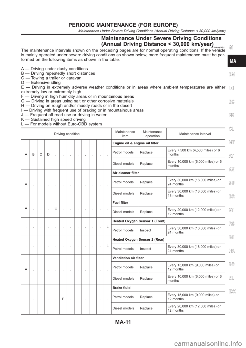
Maintenance Under Severe Driving Conditions
(Annual Driving Distance < 30,000 km/year)
=NJMA0043S03The maintenance intervals shown on the preceding pages are for normal operating conditions. If the vehicle
is mainly operated under severe driving conditions as shown below, more frequent maintenance must be per-
formed on the following items as shown in the table.
A — Driving under dusty conditions
B — Driving repeatedly short distances
C — Towing a trailer or caravan
D — Extensive idling
E — Driving in extremely adverse weather conditions or in areas where ambient temperatures are either
extremely low or extremely high
F — Driving in high humidity areas or in mountainous areas
G — Driving in areas using salt or other corrosive materials
H — Driving on rough and/or muddy roads or in the desert
I — Driving with frequent use of braking or in mountainous areas
J — Frequent off road use or driving in water
K — Sustained high speed driving
L — For models without Euro-OBD system
Driving conditionMaintenance
itemMaintenance
operationMaintenance interval
ABCD........Engine oil & engine oil filter
Petrol models ReplaceEvery 7,500 km (4,500 miles) or 6
months
Diesel models ReplaceEvery 10,000 km (6,000 miles) or 6
months
A...........Air cleaner filter
Petrol models ReplaceEvery 30,000 km (18,000 miles) or
24 months
Diesel models ReplaceEvery 30,000 km (18,000 miles) or
18 months
A...E.......Fuel filter
Diesel models ReplaceEvery 20,000 km (12,000 miles) or
12 months
...........LHeated Oxygen Sensor 1 (Front)
Petrol models InspectEvery 30,000 km (18,000 miles) or
24 months
...........LHeated Oxygen Sensor 2 (Rear)
Petrol models InspectEvery 30,000 km (18,000 miles) or
24 months
A...........Ventilation air filter
Petrol models ReplaceEvery 15,000 km (9,000 miles) or
12 months
Diesel models ReplaceEvery 10,000 km (6,000 miles) or 6
months
.....F......Brake fluid
Petrol models ReplaceEvery 15,000 km (9,000 miles) or
12 months
Diesel models ReplaceEvery 20,000 km (12,000 miles) or
12 months
GI
EM
LC
EC
FE
CL
MT
AT
AX
SU
BR
ST
RS
BT
HA
SC
EL
IDX
PERIODIC MAINTENANCE (FOR EUROPE)
Maintenance Under Severe Driving Conditions (Annual Driving Distance < 30,000 km/year)
MA-11
Page 73 of 3189
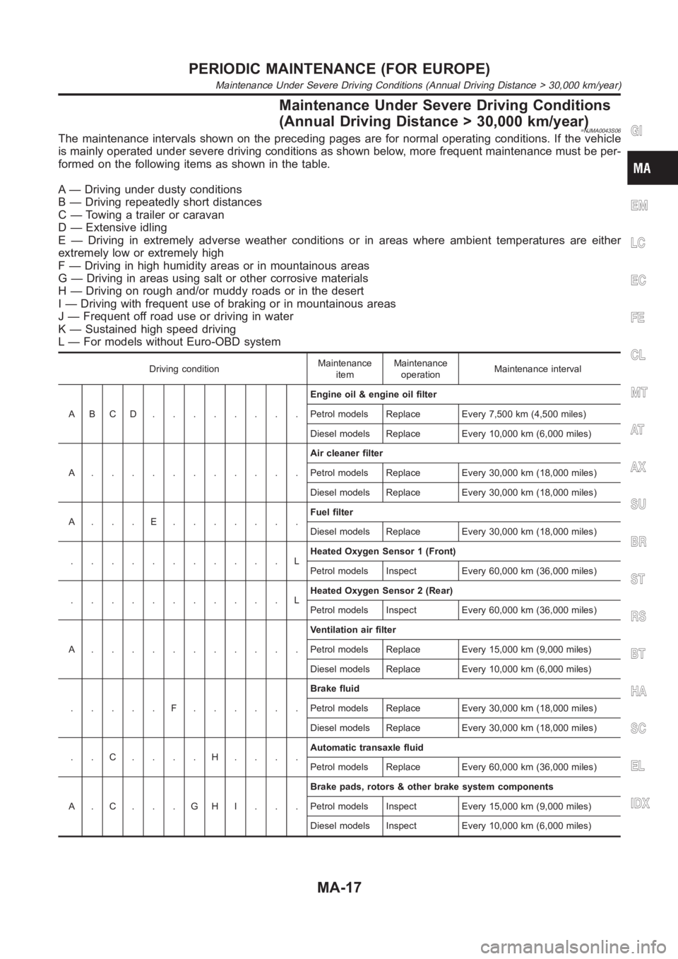
Maintenance Under Severe Driving Conditions
(Annual Driving Distance > 30,000 km/year)
=NJMA0043S06The maintenance intervals shown on the preceding pages are for normal operating conditions. If the vehicle
is mainly operated under severe driving conditions as shown below, more frequent maintenance must be per-
formed on the following items as shown in the table.
A — Driving under dusty conditions
B — Driving repeatedly short distances
C — Towing a trailer or caravan
D — Extensive idling
E — Driving in extremely adverse weather conditions or in areas where ambient temperatures are either
extremely low or extremely high
F — Driving in high humidity areas or in mountainous areas
G — Driving in areas using salt or other corrosive materials
H — Driving on rough and/or muddy roads or in the desert
I — Driving with frequent use of braking or in mountainous areas
J — Frequent off road use or driving in water
K — Sustained high speed driving
L — For models without Euro-OBD system
Driving conditionMaintenance
itemMaintenance
operationMaintenance interval
ABCD........Engine oil & engine oil filter
Petrol models Replace Every 7,500 km (4,500 miles)
Diesel models Replace Every 10,000 km (6,000 miles)
A...........Air cleaner filter
Petrol models Replace Every 30,000 km (18,000 miles)
Diesel models Replace Every 30,000 km (18,000 miles)
A...E.......Fuel filter
Diesel models Replace Every 30,000 km (18,000 miles)
...........LHeated Oxygen Sensor 1 (Front)
Petrol models Inspect Every 60,000 km (36,000 miles)
...........LHeated Oxygen Sensor 2 (Rear)
Petrol models Inspect Every 60,000 km (36,000 miles)
A...........Ventilation air filter
Petrol models Replace Every 15,000 km (9,000 miles)
Diesel models Replace Every 10,000 km (6,000 miles)
.....F......Brake fluid
Petrol models Replace Every 30,000 km (18,000 miles)
Diesel models Replace Every 30,000 km (18,000 miles)
..C....H....Automatic transaxle fluid
Petrol models Replace Every 60,000 km (36,000 miles)
A.C...GHI...Brake pads, rotors & other brake system components
Petrol models Inspect Every 15,000 km (9,000 miles)
Diesel models Inspect Every 10,000 km (6,000 miles)
GI
EM
LC
EC
FE
CL
MT
AT
AX
SU
BR
ST
RS
BT
HA
SC
EL
IDX
PERIODIC MAINTENANCE (FOR EUROPE)
Maintenance Under Severe Driving Conditions (Annual Driving Distance > 30,000 km/year)
MA-17
Page 146 of 3189
![NISSAN ALMERA N16 2003 Electronic Repair Manual EM-68
[QG]
ENGINE ASSEMBLY
WARNING:
●Position vehicle on a flat and solid surface.
●Place chocks at front and back of rear wheels.
●Do not remove engine until exhaust system has complete NISSAN ALMERA N16 2003 Electronic Repair Manual EM-68
[QG]
ENGINE ASSEMBLY
WARNING:
●Position vehicle on a flat and solid surface.
●Place chocks at front and back of rear wheels.
●Do not remove engine until exhaust system has complete](/img/5/57350/w960_57350-145.png)
EM-68
[QG]
ENGINE ASSEMBLY
WARNING:
●Position vehicle on a flat and solid surface.
●Place chocks at front and back of rear wheels.
●Do not remove engine until exhaust system has completely cooled off, otherwise, you may burn
yourself and/or fire may break out in fuel line.
●Before disconnecting fuel hose, release pressure.
Refer to EC-34 (WITH EURO-OBD), EC-428 (WITHOUT EURO-OBD).
●Be sure to lift engine and transaxle in a safe manner.
●For engines not equipped with engine slingers, attach proper slingers and bolts described in
PARTS CATALOG.
CAUTION:
●When lifting engine, be sure to clear surrounding parts. Use special care near accelerator wire
casing, brake lines and brake master cylinder.
●When lifting the engine, always use engine slingers in a safe manner.
●When removing drive shaft, be careful not to damage grease seal of transaxle.
●Before separating engine and transaxle, remove crankshaft position sensor (POS) from the cylin-
der block assembly.
●Always be extra careful not to damage edge of crankshaft position sensor (POS), or signal plate
teeth.
Engine cannot be removed separately from transaxle. Remove engine with transaxle as an assembly.
REMOVAL
1. Drain coolant from radiator and cylinder block. Refer to LC-17, "Chacking Engine Coolant".
2. Remove coolant reservoir tank and bracket.
3. Drain engine oil.
4. Remove battery and battery tray.
5. Remove air cleaner and air duct.
6. Remove drive belts.
7. Remove alternator and air conditioner compressor from engine.
8. Remove power steering oil pump from engine and position aside.
Power steering oil pump does not need to be disconnected from power steering tubes.
9. Remove the following parts:
●RH and LH front tires
●Splash covers
●RH and LH brake caliper assemblies
Refer to BR-28,"Removal".
Brake hose does not need to be disconnected from brake
caliper assembly. Never depress brake pedal.
●RH & LH drive shaft. Refer to AX-11, "Removal".
When removing drive shaft, be careful not to damage
transaxle side grease seal.
●Disconnect control rod and support rod from transaxle. (M/T
models.)
Refer to MT-26, "Removal".
●Disconnect control cable from transaxle. (A/T models.)
Refer to AT-411, "Removal".
SEM174D
SEM109G
Page 248 of 3189
crankshaft position sensor (TDC sensor) from the assem-
bly.
Always pay extra attention not to damage edge of crank-
shaft position sensor (TDC sensor) or ring gear teeth.
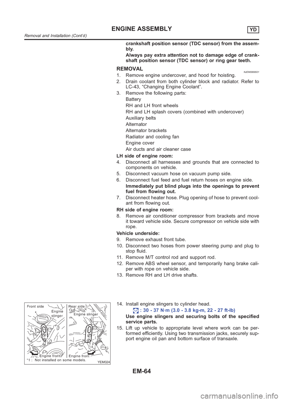
REMOVALNJEM0069S011. Remove engine undercover, and hood for hoisting.
2. Drain coolant from both cylinder block and radiator. Refer to
LC-43, “Changing Engine Coolant”.
3. Remove the following parts:
Battery
RH and LH front wheels
RH and LH splash covers (combined with undercover)
Auxiliary belts
Alternator
Alternator brackets
Radiator and cooling fan
Engine cover
Air ducts and air cleaner case
LH side of engine room:
4. Disconnect all harnesses and grounds that are connected to
components on vehicle.
5. Disconnect vacuum hose on vacuum pump side.
6. Disconnect fuel feed and fuel return hoses on engine side.
Immediately put blind plugs into the openings to prevent
fuel from flowing out.
7. Disconnect heater hose. Plug opening of hose to prevent cool-
ant from flowing out.
RH side of engine room:
8. Remove air conditioner compressor from brackets and move
it toward vehicle side. Secure compressor on vehicle side with
rope.
Vehicle underside:
9. Remove exhaust front tube.
10. Disconnect two hoses from power steering pump and plug to
stop fluid.
11. Remove M/T control rod and support rod.
12. Remove ABS wheel sensor, and temporarily hang brake cali-
per with rope on vehicle side.
13. Remove RH and LH drive shafts.
YEM024
14. Install engine slingers to cylinder head.
: 30 - 37 N·m (3.0 - 3.8 kg-m, 22 - 27 ft-lb)
Use engine slingers and securing bolts of the specified
service parts.
15. Lift up vehicle to appropriate level where work can be per-
formed efficiently. Using two transmission jacks, securely sup-
port engine oil pan and bottom surface of transaxle.
ENGINE ASSEMBLYYD
Removal and Installation (Cont’d)
EM-64
Page 335 of 3189
EC-5
C
D
E
F
G
H
I
J
K
L
M
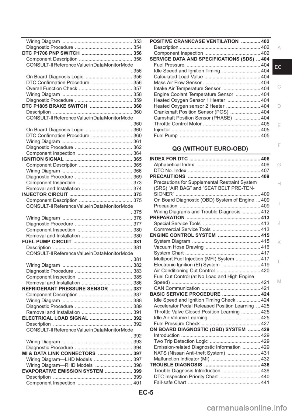
ECA Wiring Diagram .................................................... 353
Diagnostic Procedure ........................................... 354
DTC P1706 PNP SWITCH ...................................... 356
Component Description ........................................ 356
CONSULT-II Reference Value in Data Monitor Mode
. 356
On Board Diagnosis Logic ................................... 356
DTC Confirmation Procedure ............................... 356
Overall Function Check ........................................ 357
Wiring Diagram .................................................... 358
Diagnostic Procedure ........................................... 359
DTC P1805 BRAKE SWITCH ................................ 360
Description ........................................................... 360
CONSULT-II Reference Value in Data Monitor Mode
. 360
On Board Diagnosis Logic ................................... 360
DTC Confirmation Procedure ............................... 360
Wiring Diagram .................................................... 361
Diagnostic Procedure ........................................... 362
Component Inspection ......................................... 364
IGNITION SIGNAL .................................................. 365
Component Description ........................................ 365
Wiring Diagram .................................................... 366
Diagnostic Procedure ........................................... 369
Component Inspection ......................................... 373
Removal and Installation ...................................... 374
INJECTOR CIRCUIT ............................................... 375
Component Description ........................................ 375
CONSULT-II Reference Value in Data Monitor Mode
. 375
Wiring Diagram .................................................... 376
Diagnostic Procedure ........................................... 377
Component Inspection ......................................... 380
Removal and Installation ...................................... 380
FUEL PUMP CIRCUIT ............................................ 381
Description ........................................................... 381
CONSULT-II Reference Value in Data Monitor Mode
. 381
Wiring Diagram .................................................... 382
Diagnostic Procedure ........................................... 383
Component Inspection ......................................... 385
Removal and Installation ...................................... 386
REFRIGERANT PRESSURE SENSOR ................. 387
Component Description ........................................ 387
Wiring Diagram .................................................... 388
Diagnostic Procedure ........................................... 389
Removal and Installation ...................................... 391
ELECTRICAL LOAD SIGNAL ................................ 392
Description ...................................................
........ 392
CONSULT-II Reference Value in Data Monitor Mode
. 392
Wiring Diagram .................................................... 393
Diagnostic Procedure ........................................... 394
MI & DATA LINK CONNECTORS .......................... 397
Wiring Diagram—LHD Models ............................. 397
Wiring Diagram—RHD Models ............................ 398
EVAPORATIVE EMISSION SYSTEM ..................... 399
Description ........................................................... 399
Component Inspection ......................................... 401POSITIVE CRANKCASE VENTILATION ...............402
Description ............................................................402
Component Inspection ..........................................402
SERVICE DATA AND SPECIFICATIONS (SDS) ....404
Fuel Pressure .......................................................404
Idle Speed and Ignition Timing .............................404
Calculated Load Value ..........................................404
Mass Air Flow Sensor ...........................................404
Intake Air Temperature Sensor .............................404
Engine Coolant Temperature Sensor ...................404
Heated Oxygen Sensor 1 Heater .........................404
Heated Oxygen sensor 2 Heater ..........................404
Crankshaft Position Sensor (POS) .......................404
Camshaft Position Sensor (PHASE) ....................404
Throttle Control Motor ...........................................405
Injector ..................................................................405
Fuel Pump ............................................................405
QG (WITHOUT EURO-OBD)
INDEX FOR DTC .....................................................406
Alphabetical Index ................................................406
DTC No. Index ......................................................407
PRECAUTIONS ......................................................409
Precautions for Supplemental Restraint System
(SRS) “AIR BAG” and “SEAT BELT PRE-TEN-
SIONER” ...............................................................409
On Board Diagnostic (OBD) System of Engine ....409
Precaution ............................................................409
Wiring Diagrams and Trouble Diagnosis ..............412
PREPARATION .......................................................413
Special Service Tools ...........................................413
Commercial Service Tools ....................................413
ENGINE CONTROL SYSTEM ................................415
System Diagram ...................................................415
Vacuum Hose Drawing .........................................416
System Chart ........................................................417
Multiport Fuel Injection (MFI) System ...................417
Electronic Ignition (EI) System .............................419
Air Conditioning Cut Control .................................420
Fuel Cut Control (at No Load and High Engine
Speed) ..................................................................421
CAN Communication ............................................421
BASIC SERVICE PROCEDURE .............................424
Idle Speed and Ignition Timing Check ..................424
Accelerator Pedal Released Position Learning ....425
Throttle Valve Closed Position Learning ...............425
Idle Air Volume Learning ......................................425
Fuel Pressure Check ............................................427
ON BOARD DIAGNOSTIC (OBD) SYSTEM ..........429
Introduction ...........................................................429
Two Trip Detection Logic ......................................429
Emission-related Diagnostic Information ..............429
NATS (Nissan Anti-theft System) .........................431
Malfunction Indicator (MI) .....................................432
TROUBLE DIAGNOSIS ..........................................436
Trouble Diagnosis Introduction .............................436
DTC Inspection Priority Chart ...............................440
Fail-safe Chart ......................................................441
Page 338 of 3189
EC-8
Wiring Diagram .....................................................625
Diagnostic Procedure ...........................................626
DTC P1805 BRAKE SWITCH .................................628
Description ............................................................628
CONSULT-II Reference Value in Data Monitor Mode
.628
On Board Diagnosis Logic ....................................628
DTC Confirmation Procedure ...............................628
Wiring Diagram .....................................................629
Diagnostic Procedure ...........................................630
Component Inspection ..........................................632
HO2S1 HEATER .....................................................633
Description ............................................................633
CONSULT-II Reference Value in Data Monitor Mode
.633
Wiring Diagram .....................................................634
Diagnostic Procedure ...........................................635
Component Inspection ..........................................637
Removal and Installation ......................................637
HO2S2 HEATER .....................................................638
Description ............................................................638
CONSULT-II Reference Value in Data Monitor Mode
.638
Wiring Diagram .....................................................639
Diagnostic Procedure ...........................................640
Component Inspection ..........................................642
Removal and Installation ......................................642
IAT SENSOR ...........................................................643
Component Description ........................................643
Wiring Diagram .....................................................644
Diagnostic Procedure ...........................................645
Component Inspection ..........................................646
Removal and Installation ......................................646
HO2S1 .....................................................................647
Component Description ........................................647
CONSULT-II Reference Value in Data Monitor Mode
.647
Wiring Diagram .....................................................648
Diagnostic Procedure ...........................................649
Component Inspection ..........................................652
Removal and Installation ......................................653
HO2S2 .....................................................................654
Component Description ........................................654
CONSULT-II Reference Value in Data Monitor Mode
.654
Wiring Diagram .....................................................655
Diagnostic Procedure ...........................................656
Component Inspection ..........................................658
Removal and Installation ......................................659
IGNITION SIGNAL ..................................................660
Component Description ........................................660
Wiring Diagram .....................................................661
Diagnostic Procedure ...........................................664
Component Inspection ..........................................668
Removal and Installation ......................................669
EVAP CANISTER PURGE VOLUME CONTROL
SOLENOID VALVE .................................................670
Description ............................................................670
CONSULT-II Reference Value in Data Monitor Mode .670
Wiring Diagram .....................................................671
Diagnostic Procedure ............................................673
Component Inspection ..........................................676
Removal and Installation .......................................676
VSS ..........................................................................677
Description ............................................................677
Diagnostic Procedure ............................................677
POWER STEERING PRESSURE SENSOR ...........678
Component Description ........................................678
CONSULT-II Reference Value in Data Monitor Mode
.678
Wiring Diagram .....................................................679
Diagnostic Procedure ............................................680
Component Inspection ..........................................682
IVT CONTROL SOLENOID VALVE ........................683
Description ............................................................683
CONSULT-II Reference Value in Data Monitor Mode
.683
Wiring Diagram .....................................................685
Diagnostic Procedure ............................................686
Component Inspection ..........................................688
Removal and Installation .......................................688
PNP SWITCH ..........................................................689
Component Description ........................................689
CONSULT-II Reference Value in Data Monitor Mode
.689
Wiring Diagram .....................................................690
Diagnostic Procedure ............................................691
INJECTOR CIRCUIT ...............................................693
Component Description ........................................693
CONSULT-II Reference Value in Data Monitor Mode
.693
Wiring Diagram .....................................................694
Diagnostic Procedure ............................................695
Component Inspection ..........................................698
Removal and Installation ......................................
.698
FUEL PUMP CIRCUIT .............................................699
Description ............................................................699
CONSULT-II Reference Value in Data Monitor Mode
.699
Wiring Diagram .....................................................700
Diagnostic Procedure ............................................701
Component Inspection ..........................................703
Removal and Installation .......................................704
REFRIGERANT PRESSURE SENSOR ..................705
Component Description ........................................705
Wiring Diagram .....................................................706
Diagnostic Procedure ............................................707
Removal and Installation .......................................709
ELECTRICAL LOAD SIGNAL ................................710
Description ............................................................710
CONSULT-II Reference Value in Data Monitor Mode
.710
Wiring Diagram .....................................................711
Diagnostic Procedure ............................................712
MI & DATA LINK CONNECTORS ...........................715
Wiring Diagram—LHD Models ..............................715
Wiring Diagram—RHD Models .............................716
Page 340 of 3189
![NISSAN ALMERA N16 2003 Electronic Repair Manual EC-10
[QG (WITH EURO-OBD)]
INDEX FOR DTC
[QG (WITH EURO-OBD)]INDEX FOR DTCPFP:00024
Alphabetical IndexEBS00K2T
Check if the vehicle is a model with Euro-OBD (E-OBD) system or not by the “Type approv NISSAN ALMERA N16 2003 Electronic Repair Manual EC-10
[QG (WITH EURO-OBD)]
INDEX FOR DTC
[QG (WITH EURO-OBD)]INDEX FOR DTCPFP:00024
Alphabetical IndexEBS00K2T
Check if the vehicle is a model with Euro-OBD (E-OBD) system or not by the “Type approv](/img/5/57350/w960_57350-339.png)
EC-10
[QG (WITH EURO-OBD)]
INDEX FOR DTC
[QG (WITH EURO-OBD)]INDEX FOR DTCPFP:00024
Alphabetical IndexEBS00K2T
Check if the vehicle is a model with Euro-OBD (E-OBD) system or not by the “Type approval number” on the
identification plate. Refer to GI-39.
NOTE:
If DTC U1000 or U1001 is displayed with other DTC, first perform the trouble diagnosis for DTC U1000,
U1001. Refer to EC-116, "
DTC U1000, U1001 CAN COMMUNICATION LINE" .
×: Applicable –: Not applicable
Items
(CONSULT-II screen terms)DTC*
1
TripMI lighting
upReference page
CONSULT-II
GST*
2ECM*3
A/T 1ST GR FNCTN P0731 0731 2×AT-133
A/T 2ND GR FNCTN P0732 0732 2×AT-139
A/T 3RD GR FNCTN P0733 0733 2×AT-145
A/T 4TH GR FNCTN P0734 0734 2×AT-151
APP SEN 1/CIRC P0227 0227 1×EC-218
APP SEN 1/CIRC P0228 0228 1×EC-218
APP SEN 2/CIRC P1227 1227 1×EC-345
APP SEN 2/CIRC P1228 1228 1×EC-345
APP SENSOR P0226 0226 1×EC-211
ATF TEMP SEN/CIRC P0710 0710 2×AT- 11 7
BRAKE SW/CIRCUIT P1805 1805 2 –EC-360
CAN COMM CIRCUIT U1000
1000*51×EC-116
CAN COMM CIRCUIT U1001
1001*52–EC-116
CKP SEN/CIRCUIT P0335 0335 2×EC-234
CMP SEN/CIRC-B1 P0340 0340 2×EC-240
CTP LEARNING P1225 1225 2 –EC-341
CTP LEARNING P1226 1226 2 –EC-343
CYL 1 MISFIRE P0301 0301 2×EC-225
CYL 2 MISFIRE P0302 0302 2×EC-225
CYL 3 MISFIRE P0303 0303 2×EC-225
CYL 4 MISFIRE P0304 0304 2×EC-225
ECM P0605 0605 1 or 2× or –EC-265
ECM BACK UP/CIRC P1065 1065 2×EC-268
ECT SEN/CIRCUIT P0117 0117 1×EC-144
ECT SEN/CIRCUIT P0118 0118 1×EC-144
ENG OVER TEMP P1217 1217 1×EC-324
ENGINE SPEED SIG P0725 0725 1×AT-129
ETC ACTR P1121 1121 1 or 2×EC-276
ETC FUNCTION/CIRC P1122 1122 1×EC-278
ETC MOT P1128 1128 1×EC-291
ETC MOT PWR P1124 1124 1×EC-285
ETC MOT PWR P1126 1126 1×EC-285
FUEL SYS-LEAN-B1 P0171 0171 2×EC-186
FUEL SYS-RICH-B1 P0172 0172 2×EC-193
HO2S1 (B1) P0132 0132 2×EC-149
Page 344 of 3189
![NISSAN ALMERA N16 2003 Electronic Repair Manual EC-14
[QG (WITH EURO-OBD)]
INDEX FOR DTC
*1: 1st trip DTC No. is the same as DTC No.
*2: These numbers are prescribed by ISO 15031-5.
*3: In Diagnostic Test Mode II (Self-diagnostic results), these nu NISSAN ALMERA N16 2003 Electronic Repair Manual EC-14
[QG (WITH EURO-OBD)]
INDEX FOR DTC
*1: 1st trip DTC No. is the same as DTC No.
*2: These numbers are prescribed by ISO 15031-5.
*3: In Diagnostic Test Mode II (Self-diagnostic results), these nu](/img/5/57350/w960_57350-343.png)
EC-14
[QG (WITH EURO-OBD)]
INDEX FOR DTC
*1: 1st trip DTC No. is the same as DTC No.
*2: These numbers are prescribed by ISO 15031-5.
*3: In Diagnostic Test Mode II (Self-diagnostic results), these numbers are controlled by NISSAN.
*4: When engine is running.
*5: The trouble shooting for this DTC needs CONSULT-II.
*6: When the fail-safe operations for both self-diagnoses occur, the MI illuminates. P1217 1217 ENG OVER TEMP 1×EC-324
P1223 1223 TP SEN 2/CIRC 1×EC-335
P1224 1224 TP SEN 2/CIRC 1×EC-335
P1225 1225 CTP LEARNING 2 –EC-341
P1226 1226 CTP LEARNING 2 –EC-343
P1227 1227 APP SEN 2/CIRC 1×EC-345
P1228 1228 APP SEN 2/CIRC 1×EC-345
P1229 1229 SENSOR POWER/CIRC 1×EC-352
P1610 - P1615 1610 - 1615 NATS MALFUNCTION 2 –EC-49
P1705 1705 TPV SEN/CIRC A/T 1×AT-181
P1706 1706 P-N POS SW/CIRCUIT 2×EC-356
P1760 1760 O/R CLTCH SOL/CIRC 2×AT-187
P1805 1805 BRAKE SW/CIRCUIT 2 –EC-360
DTC*1
Items
(CONSULT-II screen terms)TripMI lighting
upReference page
CONSULT-II
GST*
2ECM*3
Page 357 of 3189
![NISSAN ALMERA N16 2003 Electronic Repair Manual ENGINE CONTROL SYSTEM
EC-27
[QG (WITH EURO-OBD)]
C
D
E
F
G
H
I
J
K
L
MA
EC
Fuel Cut Control (at No Load and High Engine Speed)EBS00K38
INPUT/OUTPUT SIGNAL CHART
*1: This signal is sent to the ECM thro NISSAN ALMERA N16 2003 Electronic Repair Manual ENGINE CONTROL SYSTEM
EC-27
[QG (WITH EURO-OBD)]
C
D
E
F
G
H
I
J
K
L
MA
EC
Fuel Cut Control (at No Load and High Engine Speed)EBS00K38
INPUT/OUTPUT SIGNAL CHART
*1: This signal is sent to the ECM thro](/img/5/57350/w960_57350-356.png)
ENGINE CONTROL SYSTEM
EC-27
[QG (WITH EURO-OBD)]
C
D
E
F
G
H
I
J
K
L
MA
EC
Fuel Cut Control (at No Load and High Engine Speed)EBS00K38
INPUT/OUTPUT SIGNAL CHART
*1: This signal is sent to the ECM through CAN communication line.
SYSTEM DESCRIPTION
If the engine speed is above 3,950 rpm with no load (for example, in neutral and engine speed over 3,950
rpm) fuel will be cut off after some time. The exact time when the fuel is cut off varies based on engine speed.
Fuel cut will operate until the engine speed reaches 1,500 rpm, then fuel cut is cancelled.
NOTE:
This function is different from deceleration control listed under “Multiport Fuel Injection (MFI) System”, EC-23
.
CAN CommunicationEBS00K39
SYSTEM DESCRIPTION
CAN (Controller Area Network) is a serial communication line for real time application. It is an on-vehicle mul-
tiplex communication line with high data communication speed and excellent error detection ability. Many elec-
tronic control units are equipped onto a vehicle, and each control unit shares information and links with other
control units during operation (not independent). In CAN communication, control units are connected with 2
communication lines (CAN H line, CAN L line) allowing a high rate of information transmission with less wiring.
Each control unit transmits/receives data but selectively reads required data only.
CAN COMMUNICATION UNIT
×:ApplicableSensor Input Signal to ECM ECM Function Actuator
Park/neutral position (PNP) switch Neutral position
Fuel cut control Fuel injectors Throttle position sensor Throttle position
Accelerator pedal position sensor Accelerator pedal position
Engine coolant temperature sensor Engine coolant temperature
Crankshaft position sensor (POS)
Camshaft position sensor (PHASE)Engine speed
Vehicle speed signal
*1Vehicle speed
Body type Sedan/ 5DH/B/ 3DH/B
Axle2WD
Engine QG18DE QG15DE/QG18DE
Transmission A/T M/T
Brake controlABS
CAN communication unit
ECM××
TCM×
Smart entrance control unit××
Data link connector××
Combination meter××
CAN communication type EC-28, "
Type 1"EC-29, "Ty p e 2"
Page 393 of 3189
![NISSAN ALMERA N16 2003 Electronic Repair Manual TROUBLE DIAGNOSIS
EC-63
[QG (WITH EURO-OBD)]
C
D
E
F
G
H
I
J
K
L
MA
EC
Fail-safe ChartEBS00K3N
●When the DTC listed below is detected, the ECM enters fail-safe mode and the MI lights up.
Priority De NISSAN ALMERA N16 2003 Electronic Repair Manual TROUBLE DIAGNOSIS
EC-63
[QG (WITH EURO-OBD)]
C
D
E
F
G
H
I
J
K
L
MA
EC
Fail-safe ChartEBS00K3N
●When the DTC listed below is detected, the ECM enters fail-safe mode and the MI lights up.
Priority De](/img/5/57350/w960_57350-392.png)
TROUBLE DIAGNOSIS
EC-63
[QG (WITH EURO-OBD)]
C
D
E
F
G
H
I
J
K
L
MA
EC
Fail-safe ChartEBS00K3N
●When the DTC listed below is detected, the ECM enters fail-safe mode and the MI lights up.
Priority Detected items (DTC)
1
●U1000 U1001 CAN communication line
●P0102 P0103 Mass air flow sensor
●P0112 P0113 Intake air temperature sensor
●P0117 P0118 Engine coolant temperature sensor
●P0221 P0222 P0223 P1223 P1224 P1225 P1226 P1229 Throttle position sensor
●P0226 P0227 P0228 P1227 P1228 Accelerator pedal position sensor
●P0327 P0328 Knock sensor
●P0335 Crankshaft position sensor (POS)
●P0340 Camshaft position sensor (PHASE)
●P0500 Vehicle speed sensor
●P0705 Park/Neutral position (PNP) switch
●P0605 ECM
●P1610-P1615 NATS
●P1706 Park/Neutral position (PNP) switch
2
●P0031 P0032 Heated oxygen sensor 1 heater
●P0037 P0038 Heated oxygen sensor 2 heater
●P0132 P0133 P0134 P1143 P1144 Heated oxygen sensor 1
●P0138 P0139 P1146 P1147 Heated oxygen sensor 2
●P0550 Power steering pressure sensor
●P0710-P0725 P0740-P0755 P1705 P1760 A/T related sensors and solenoid valves
●P1065 ECM power supply
●P 1111 I n ta k e v a l v e t i m i n g c o n t r o l s o l e n o i d v a l v e
●P1122 Electric throttle control function
●P1124 P1126 P1128 Electric throttle control actuator
●P1805 Brake switch
3
●P0011 Intake valve timing control
●P0171 P0172 Fuel injection system function
●P0300 - P0304 Misfire
●P0420 Three way catalyst function
●P0444 EVAP canister purge volume control solenoid valve
●P0731-P0734 A/T function
●P1121 Electric throttle control actuator
●P1217 Engine over temperature (OVERHEAT)
DTC No. Detected items Engine operating condition in fail-safe mode
P0102
P0103Mass air flow sensor circuit Engine speed will not rise more than 2,400 rpm due to the fuel cut.