weight NISSAN ALMERA N16 2003 Electronic Repair Manual
[x] Cancel search | Manufacturer: NISSAN, Model Year: 2003, Model line: ALMERA N16, Model: NISSAN ALMERA N16 2003Pages: 3189, PDF Size: 54.76 MB
Page 6 of 3189

The security indicator is located on the combi meter. The indicator
blinks when the ignition switch is in “OFF” or “ACC” position.
Therefore, NATS warns outsiders that the vehicle is equipped with
the anti-theft system.
When NATS detects trouble, the security indicator lamp lights
up while ignition switch is in “ON” position.
This lighting up indicates that the anti-theft is not functioning,
so prompt service is required.
When servicing NATS (trouble diagnoses, system initialization
and additional registration of other NATS ignition key IDs),
CONSULT-II hardware and CONSULT-II NATS software is
necessary.
Regarding the procedures of NATS initialization and NATS
ignition key ID registration, refer to CONSULT-II operation
manual, NATS.
Therefore, CONSULT-II NATS software (program card and
operation manual) must be kept strictly confidential to main-
tain the integrity of the anti-theft function.
When servicing NATS (trouble diagnoses, system initialization
and additional registration of other NATS ignition key IDs), it
may be necessary to re-register original key identification.
Therefore, be sure to receive all keys from vehicle owner. A
maximum of five key IDs can be registered into NATS.
When failing to start the engine first time using the key of
NATS, start as follows.
a) Leave the ignition key in “ON” position for approximately 5
seconds.
b) Turn ignition key to “OFF” or “LOCK” position and wait approxi-
mately 5 seconds.
c) Repeat step 1 and 2 again.
d) Restart the engine while keeping the key separate from any
others on key-chain.
SGI285
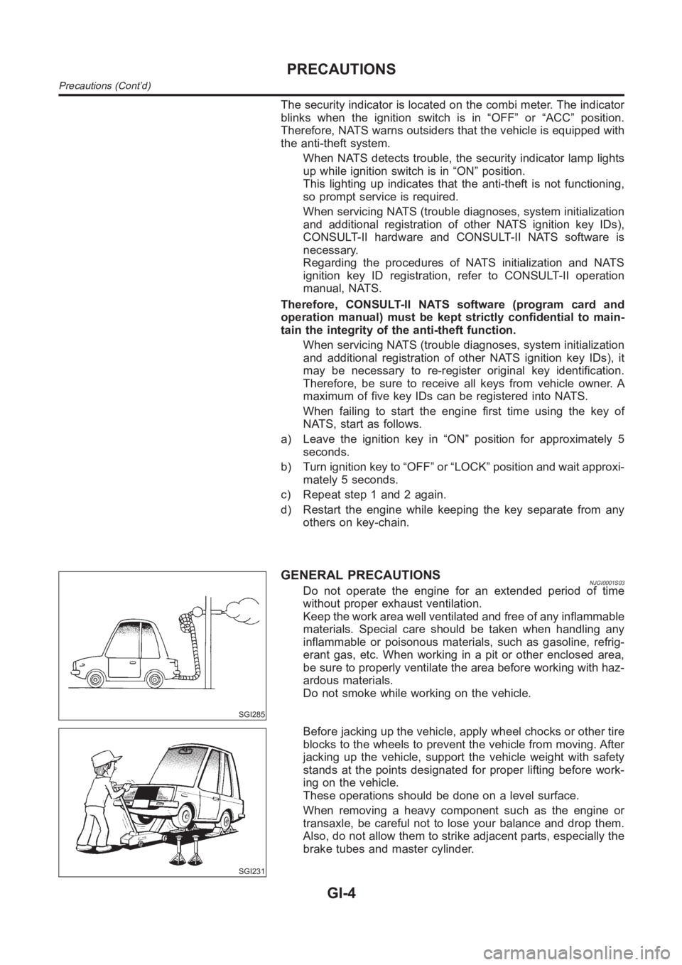
GENERAL PRECAUTIONSNJGI0001S03Do not operate the engine for an extended period of time
without proper exhaust ventilation.
Keep the work area well ventilated and free of any inflammable
materials. Special care should be taken when handling any
inflammable or poisonous materials, such as gasoline, refrig-
erant gas, etc. When working in a pit or other enclosed area,
be sure to properly ventilate the area before working with haz-
ardous materials.
Do not smoke while working on the vehicle.
SGI231
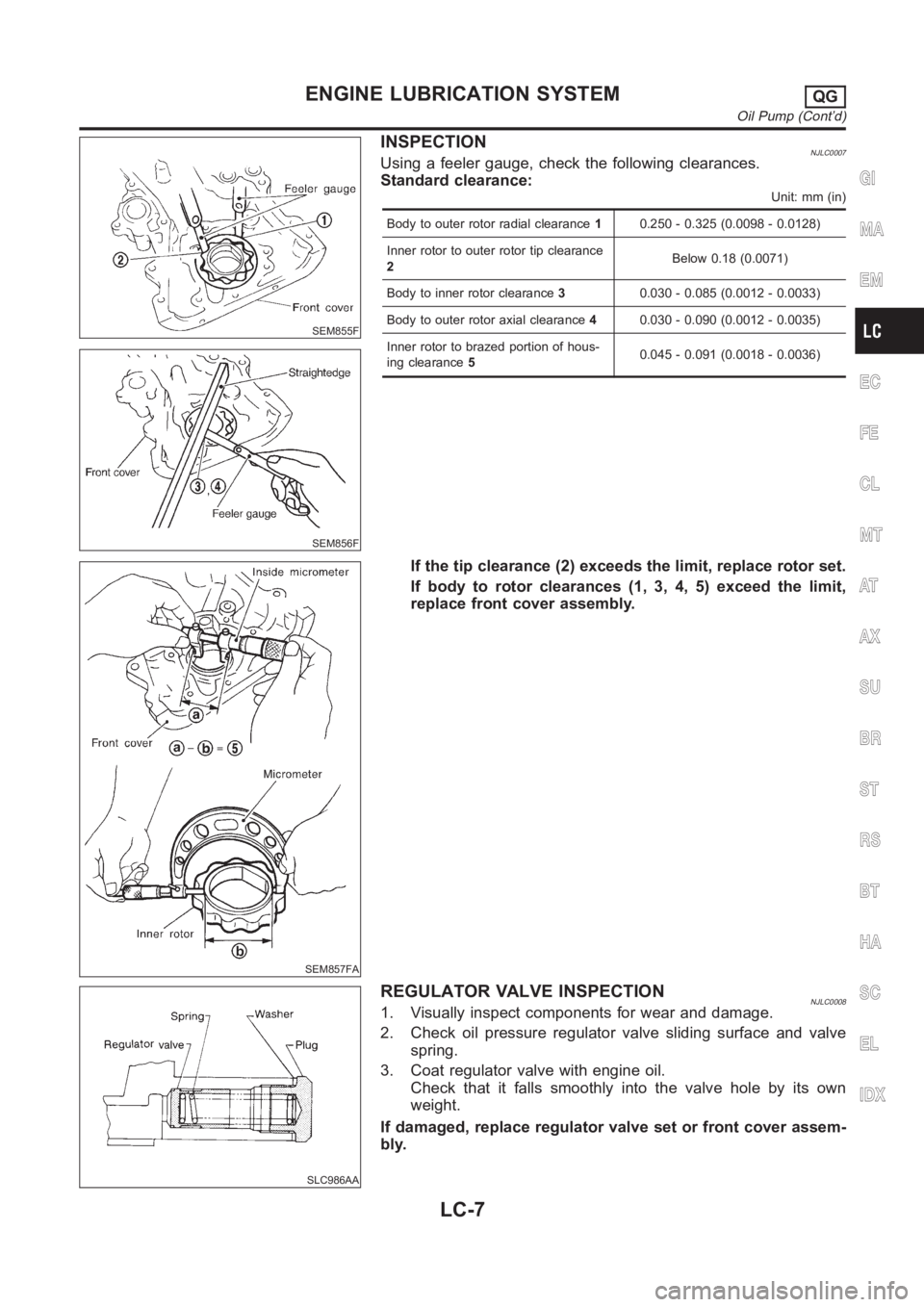
Before jacking up the vehicle, apply wheel chocks or other tire
blocks to the wheels to prevent the vehicle from moving. After
jacking up the vehicle, support the vehicle weight with safety
stands at the points designated for proper lifting before work-
ing on the vehicle.
These operations should be done on a level surface.
When removing a heavy component such as the engine or
transaxle, be careful not to lose your balance and drop them.
Also, do not allow them to strike adjacent parts, especially the
brake tubes and master cylinder.
PRECAUTIONS
Precautions (Cont’d)
GI-4
Page 20 of 3189

SGI862-A
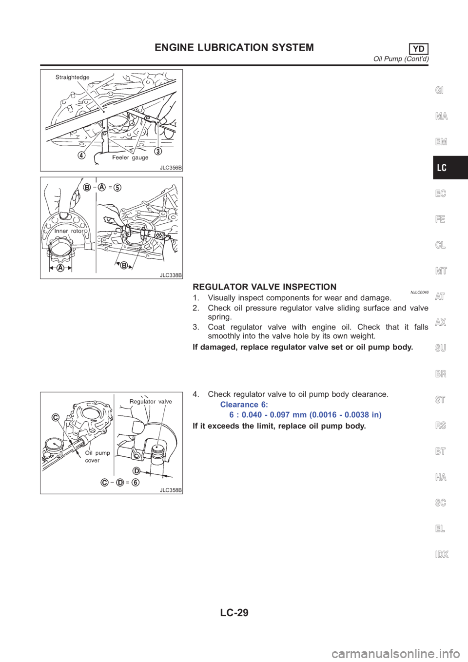
DETECTABLE LINES AND NON-DETECTABLE LINESNJGI0003S0205In some wiring diagrams, two kinds of lines, representing wires,
with different weight are used.
A line with regular weight (wider line) represents a “detectable
line for DTC (Diagnostic Trouble Code)”. A “detectable line for
DTC” is a circuit in which ECM can detect its malfunctions with
the on board diagnostic system.
A line with less weight (thinner line) represents a “non-detect-
able line for DTC”. A “non-detectable line for DTC” is a circuit
in which ECM cannot detect its malfunctions with the on board
diagnostic system.
HOW TO READ WIRING DIAGRAMS
Description (Cont’d)
GI-18
Page 127 of 3189
![NISSAN ALMERA N16 2003 Electronic Repair Manual TIMING CHAIN
EM-49
[QG]
C
D
E
F
G
H
I
J
K
L
MA
EM
b. Make sure that the camshaft sprocket mating mark is in the
position shown in the figure.
●If the mating mark is not in position, turn t NISSAN ALMERA N16 2003 Electronic Repair Manual TIMING CHAIN
EM-49
[QG]
C
D
E
F
G
H
I
J
K
L
MA
EM
b. Make sure that the camshaft sprocket mating mark is in the
position shown in the figure.
●If the mating mark is not in position, turn t](/img/5/57350/w960_57350-126.png)
TIMING CHAIN
EM-49
[QG]
C
D
E
F
G
H
I
J
K
L
MA
EM
b. Make sure that the camshaft sprocket mating mark is in the
position shown in the figure.
●If the mating mark is not in position, turn the crankshaft pulley
once more and position it.
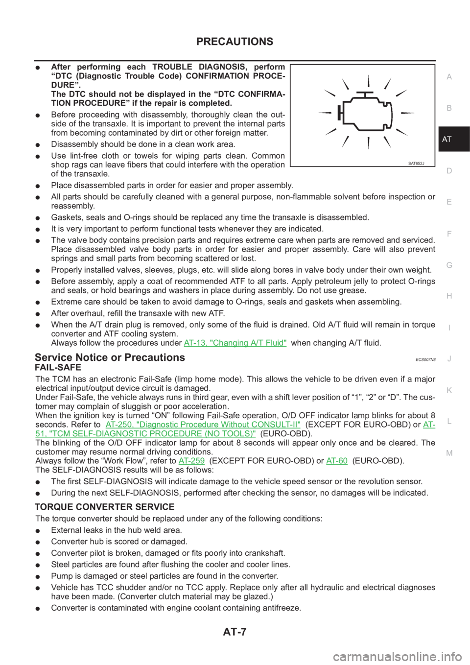
22. Remove crankshaft pulley with the following procedure:
a. Secure crankshaft counter weight with handle of a hammer, and
loosen crankshaft pulley bolts.
CAUTION:
Take care to prevent foreign material from entering the
engine.
b. Remove crankshaft pulley using crankshaft pulley puller (com-
mercial service tool).
CAUTION:
●Hook tab onto back of crankshaft pulley only.
●Do not remove crankshaft pulley bolt. Fully loosen, and
then use it as support point.
NOTE:
If oil pan is not removed, remove crankshaft pulley as follows.
i. Remove rear plate (lower).
ii. Engage drive plate ring gear with a flat-head screwdriver to fix
crankshaft in position, and loosen crankshaft pulley bolt.
iii. Remove crankshaft pulley using crankshaft pulley puller (com-
mercial service tool).
23. Remove water pump pulley and idler pulley bracket assembly.
MBIB0194E
PBIC0565E
KBIA1437E
KBIA1438E
Page 289 of 3189

SEM855F
SEM856F
INSPECTIONNJLC0007Using a feeler gauge, check the following clearances.
Standard clearance:
Unit: mm (in)
Body to outer rotor radial clearance10.250 - 0.325 (0.0098 - 0.0128)
Inner rotor to outer rotor tip clearance
2Below 0.18 (0.0071)
Body to inner rotor clearance30.030 - 0.085 (0.0012 - 0.0033)
Body to outer rotor axial clearance40.030 - 0.090 (0.0012 - 0.0035)
Inner rotor to brazed portion of hous-
ing clearance50.045 - 0.091 (0.0018 - 0.0036)
SEM857FA
If the tip clearance (2) exceeds the limit, replace rotor set.
If body to rotor clearances (1, 3, 4, 5) exceed the limit,
replace front cover assembly.
SLC986AA
REGULATOR VALVE INSPECTIONNJLC00081. Visually inspect components for wear and damage.
2. Check oil pressure regulator valve sliding surface and valve
spring.
3. Coat regulator valve with engine oil.
Check that it falls smoothly into the valve hole by its own
weight.
If damaged, replace regulator valve set or front cover assem-
bly.
GI
MA
EM
EC
FE
CL
MT
AT
AX
SU
BR
ST
RS
BT
HA
SC
EL
IDX
ENGINE LUBRICATION SYSTEMQG
Oil Pump (Cont’d)
LC-7
Page 311 of 3189

JLC356B
JLC338B
REGULATOR VALVE INSPECTIONNJLC00461. Visually inspect components for wear and damage.
2. Check oil pressure regulator valve sliding surface and valve
spring.
3. Coat regulator valve with engine oil. Check that it falls
smoothly into the valve hole by its own weight.
If damaged, replace regulator valve set or oil pump body.
JLC358B
4. Check regulator valve to oil pump body clearance.
Clearance 6:
6 : 0.040 - 0.097 mm (0.0016 - 0.0038 in)
If it exceeds the limit, replace oil pump body.
GI
MA
EM
EC
FE
CL
MT
AT
AX
SU
BR
ST
RS
BT
HA
SC
EL
IDX
ENGINE LUBRICATION SYSTEMYD
Oil Pump (Cont’d)
LC-29
Page 401 of 3189
![NISSAN ALMERA N16 2003 Electronic Repair Manual TROUBLE DIAGNOSIS
EC-71
[QG (WITH EURO-OBD)]
C
D
E
F
G
H
I
J
K
L
MA
EC
1 - 6: The numbers refer to the order of inspection.
(continued on next page)
SYSTEM — ENGINE MECHANICAL & OTHER
Power steering NISSAN ALMERA N16 2003 Electronic Repair Manual TROUBLE DIAGNOSIS
EC-71
[QG (WITH EURO-OBD)]
C
D
E
F
G
H
I
J
K
L
MA
EC
1 - 6: The numbers refer to the order of inspection.
(continued on next page)
SYSTEM — ENGINE MECHANICAL & OTHER
Power steering](/img/5/57350/w960_57350-400.png)
TROUBLE DIAGNOSIS
EC-71
[QG (WITH EURO-OBD)]
C
D
E
F
G
H
I
J
K
L
MA
EC
1 - 6: The numbers refer to the order of inspection.
(continued on next page)
SYSTEM — ENGINE MECHANICAL & OTHER
Power steering pressure sensor circuit 2 3 3 3 3EC-260
ECM 22333333333EC-265,
EC-268
Intake valve timing control solenoid valve cir-
cuit332 13223 3EC-272
PNP switch circuit 3 33333 3EC-356
Refrigerant pressure sensor circuit 2 3 3 3 3 4EC-387
Electrical load signal circuit 3 3 3 3EC-392
Air conditioner circuit223333333 3 2AT C - 2 9
SYMPTOM
Reference
page
HARD/NO START/RESTART (EXCP. HA)
ENGINE STALL
HESITATION/SURGING/FLAT SPOT
SPARK KNOCK/DETONATION
LACK OF POWER/POOR ACCELERATION
HIGH IDLE/LOW IDLE
ROUGH IDLE/HUNTING
IDLING VIBRATION
SLOW/NO RETURN TO IDLE
OVERHEATS/WATER TEMPERATURE HIGH
EXCESSIVE FUEL CONSUMPTION
EXCESSIVE OIL CONSUMPTION
BATTERY DEAD (UNDER CHARGE)
Warranty symptom code AA AB AC AD AE AF AG AH AJ AK AL AM HA
Fuel Fuel tank
5
5FE-4
Fuel piping 5 5 5 5 5 5 FE-4
Vapor lock—
Valve deposit
555555 5—
Poor fuel (Heavy weight gaso-
line, Low octane)—
Page 779 of 3189
![NISSAN ALMERA N16 2003 Electronic Repair Manual TROUBLE DIAGNOSIS
EC-449
[QG (WITHOUT EURO-OBD)]
C
D
E
F
G
H
I
J
K
L
MA
EC
1 - 6: The numbers refer to the order of inspection.
(continued on next page)
SYSTEM — ENGINE MECHANICAL & OTHER
ECM 223333 NISSAN ALMERA N16 2003 Electronic Repair Manual TROUBLE DIAGNOSIS
EC-449
[QG (WITHOUT EURO-OBD)]
C
D
E
F
G
H
I
J
K
L
MA
EC
1 - 6: The numbers refer to the order of inspection.
(continued on next page)
SYSTEM — ENGINE MECHANICAL & OTHER
ECM 223333](/img/5/57350/w960_57350-778.png)
TROUBLE DIAGNOSIS
EC-449
[QG (WITHOUT EURO-OBD)]
C
D
E
F
G
H
I
J
K
L
MA
EC
1 - 6: The numbers refer to the order of inspection.
(continued on next page)
SYSTEM — ENGINE MECHANICAL & OTHER
ECM 22333333333EC-568,
EC-571
Intake valve timing control solenoid valve cir-
cuit332 13223 3EC-683
PNP switch circuit 3 33333 3EC-689
Refrigerant pressure sensor circuit 2 3 3 3 3 4EC-705
Electrical load signal circuit 3 3 3 3EC-710
Air conditioner circuit223333333 3 2AT C - 2 9
SYMPTOM
Reference
page
HARD/NO START/RESTART (EXCP. HA)
ENGINE STALL
HESITATION/SURGING/FLAT SPOT
SPARK KNOCK/DETONATION
LACK OF POWER/POOR ACCELERATION
HIGH IDLE/LOW IDLE
ROUGH IDLE/HUNTING
IDLING VIBRATION
SLOW/NO RETURN TO IDLE
OVERHEATS/WATER TEMPERATURE HIGH
EXCESSIVE FUEL CONSUMPTION
EXCESSIVE OIL CONSUMPTION
BATTERY DEAD (UNDER CHARGE)
Warranty symptom code AA AB AC AD AE AF AG AH AJ AK AL AM HA
SYMPTOM
Reference
page
HARD/NO START/RESTART (EXCP. HA)
ENGINE STALL
HESITATION/SURGING/FLAT SPOT
SPARK KNOCK/DETONATION
LACK OF POWER/POOR ACCELERATION
HIGH IDLE/LOW IDLE
ROUGH IDLE/HUNTING
IDLING VIBRATION
SLOW/NO RETURN TO IDLE
OVERHEATS/WATER TEMPERATURE HIGH
EXCESSIVE FUEL CONSUMPTION
EXCESSIVE OIL CONSUMPTION
BATTERY DEAD (UNDER CHARGE)
Warranty symptom code AA AB AC AD AE AF AG AH AJ AK AL AM HA
Fuel Fuel tank
5
5FE-4
Fuel piping 5 5 5 5 5 5 FE-4
Vapor lock—
Valve deposit
555555 5—
Poor fuel (Heavy weight gaso-
line, Low octane)—
Page 1463 of 3189

PRECAUTIONS
AT-7
D
E
F
G
H
I
J
K
L
MA
B
AT
●After performing each TROUBLE DIAGNOSIS, perform
“DTC (Diagnostic Trouble Code) CONFIRMATION PROCE-
DURE”.
The DTC should not be displayed in the “DTC CONFIRMA-
TION PROCEDURE” if the repair is completed.
●Before proceeding with disassembly, thoroughly clean the out-
side of the transaxle. It is important to prevent the internal parts
from becoming contaminated by dirt or other foreign matter.
●Disassembly should be done in a clean work area.
●Use lint-free cloth or towels for wiping parts clean. Common
shop rags can leave fibers that could interfere with the operation
of the transaxle.
●Place disassembled parts in order for easier and proper assembly.
●All parts should be carefully cleaned with a general purpose, non-flammable solvent before inspection or
reassembly.
●Gaskets, seals and O-rings should be replaced any time the transaxle is disassembled.
●It is very important to perform functional tests whenever they are indicated.
●The valve body contains precision parts and requires extreme care when parts are removed and serviced.
Place disassembled valve body parts in order for easier and proper assembly. Care will also prevent
springs and small parts from becoming scattered or lost.
●Properly installed valves, sleeves, plugs, etc. will slide along bores in valve body under their own weight.
●Before assembly, apply a coat of recommended ATF to all parts. Apply petroleum jelly to protect O-rings
and seals, or hold bearings and washers in place during assembly. Do not use grease.
●Extreme care should be taken to avoid damage to O-rings, seals and gaskets when assembling.
●After overhaul, refill the transaxle with new ATF.
●When the A/T drain plug is removed, only some of the fluid is drained. Old A/T fluid will remain in torque
converter and ATF cooling system.
Always follow the procedures under AT-13, "
Changing A/T Fluid" when changing A/T fluid.
Service Notice or PrecautionsECS007N8
FA I L - S A F E
The TCM has an electronic Fail-Safe (limp home mode). This allows the vehicle to be driven even if a major
electrical input/output device circuit is damaged.
Under Fail-Safe, the vehicle always runs in third gear, even with a shift lever position of “1”, “2” or “D”. The cus-
tomer may complain of sluggish or poor acceleration.
When the ignition key is turned “ON” following Fail-Safe operation, O/D OFF indicator lamp blinks for about 8
seconds. Refer to AT- 2 5 0 , "
Diagnostic Procedure Without CONSULT-II" (EXCEPT FOR EURO-OBD) or AT-
51, "TCM SELF-DIAGNOSTIC PROCEDURE (NO TOOLS)" (EURO-OBD).
The blinking of the O/D OFF indicator lamp for about 8 seconds will appear only once and be cleared. The
customer may resume normal driving conditions.
Always follow the “Work Flow”, refer to AT- 2 5 9
(EXCEPT FOR EURO-OBD) or AT- 6 0 (EURO-OBD).
The SELF-DIAGNOSIS results will be as follows:
●The first SELF-DIAGNOSIS will indicate damage to the vehicle speed sensor or the revolution sensor.
●During the next SELF-DIAGNOSIS, performed after checking the sensor, no damages will be indicated.
TORQUE CONVERTER SERVICE
The torque converter should be replaced under any of the following conditions:
●External leaks in the hub weld area.
●Converter hub is scored or damaged.
●Converter pilot is broken, damaged or fits poorly into crankshaft.
●Steel particles are found after flushing the cooler and cooler lines.
●Pump is damaged or steel particles are found in the converter.
●Vehicle has TCC shudder and/or no TCC apply. Replace only after all hydraulic and electrical diagnoses
have been made. (Converter clutch material may be glazed.)
●Converter is contaminated with engine coolant containing antifreeze.
SAT652J
Page 1593 of 3189
![NISSAN ALMERA N16 2003 Electronic Repair Manual DTC P0731 A/T 1ST GEAR FUNCTION
AT-137
[EURO-OBD]
D
E
F
G
H
I
J
K
L
MA
B
AT
Diagnostic ProcedureECS007OK
1.CHECK SHIFT SOLENOID VALVE
1. Remove control valve assembly. Refer to AT- 4 0 6 , "
Con NISSAN ALMERA N16 2003 Electronic Repair Manual DTC P0731 A/T 1ST GEAR FUNCTION
AT-137
[EURO-OBD]
D
E
F
G
H
I
J
K
L
MA
B
AT
Diagnostic ProcedureECS007OK
1.CHECK SHIFT SOLENOID VALVE
1. Remove control valve assembly. Refer to AT- 4 0 6 , "
Con](/img/5/57350/w960_57350-1592.png)
DTC P0731 A/T 1ST GEAR FUNCTION
AT-137
[EURO-OBD]
D
E
F
G
H
I
J
K
L
MA
B
AT
Diagnostic ProcedureECS007OK
1.CHECK SHIFT SOLENOID VALVE
1. Remove control valve assembly. Refer to AT- 4 0 6 , "
Control Valve Assembly and Accumulators"
2. Check shift solenoid valve operation.
●Shift solenoid valve A
●Shift solenoid valve B
Refer to AT-138, "
Component Inspection" .
OK or NG
OK >> GO TO 2
NG >> Repair or replace shift solenoid valve assembly.
2.CHECK CONTROL VALVE
1. Disassemble control valve assembly. Refer to AT-439, "
Control Valve Assembly" .
2. Check to ensure that:
●Valve, sleeve and plug slide along valve bore under their own weight.
●Valve, sleeve and plug are free from burrs, dents and scratches.
●Control valve springs are free from damage, deformation and fatigue.
●Hydraulic line is free from obstacles.
OK or NG
OK >> GO TO 3
NG >> Repair control valve assembly.
3.CHECK DTC
Perform AT- 1 3 4 , "
DIAGNOSTIC TROUBLE CODE (DTC) CONFIRMATION PROCEDURE" .
OK or NG
OK >>INSPECTION END
NG >> Check control valve again. Repair or replace control valve assembly.
SAT883JB
SAT367H
Page 1599 of 3189
![NISSAN ALMERA N16 2003 Electronic Repair Manual DTC P0732 A/T 2ND GEAR FUNCTION
AT-143
[EURO-OBD]
D
E
F
G
H
I
J
K
L
MA
B
AT
Diagnostic ProcedureECS007OO
1.CHECK SHIFT SOLENOID VALVE
1. Remove control valve assembly. Refer to AT- 4 0 6 , "
Con NISSAN ALMERA N16 2003 Electronic Repair Manual DTC P0732 A/T 2ND GEAR FUNCTION
AT-143
[EURO-OBD]
D
E
F
G
H
I
J
K
L
MA
B
AT
Diagnostic ProcedureECS007OO
1.CHECK SHIFT SOLENOID VALVE
1. Remove control valve assembly. Refer to AT- 4 0 6 , "
Con](/img/5/57350/w960_57350-1598.png)
DTC P0732 A/T 2ND GEAR FUNCTION
AT-143
[EURO-OBD]
D
E
F
G
H
I
J
K
L
MA
B
AT
Diagnostic ProcedureECS007OO
1.CHECK SHIFT SOLENOID VALVE
1. Remove control valve assembly. Refer to AT- 4 0 6 , "
Control Valve Assembly and Accumulators" .
2. Check shift solenoid valve operation.
●Shift solenoid valve B
Refer to AT-144, "
Component Inspection" .
OK or NG
OK >> GO TO 2
NG >> Repair or replace shift solenoid valve assembly.
2.CHECK CONTROL VALVE
1. Disassemble control valve assembly. Refer to AT-439, "
Control Valve Assembly" .
2. Check to ensure that:
●Valve, sleeve and plug slide along valve bore under their own weight.
●Valve, sleeve and plug are free from burrs, dents and scratches.
●Control valve springs are free from damage, deformation and fatigue.
●Hydraulic line is free from obstacles.
OK or NG
OK >> GO TO 3
NG >> Repair control valve assembly.
3.CHECK DTC
Perform AT- 1 4 0 , "
DIAGNOSTIC TROUBLE CODE (DTC) CONFIRMATION PROCEDURE" .
OK or NG
OK >>INSPECTION END
NG >> Check control valve again. Repair or replace control valve assembly.
SAT884JB
SAT367H