ABS NISSAN ALMERA TINO 2001 Service Owners Manual
[x] Cancel search | Manufacturer: NISSAN, Model Year: 2001, Model line: ALMERA TINO, Model: NISSAN ALMERA TINO 2001Pages: 3051, PDF Size: 46.38 MB
Page 2697 of 3051

A
A/C HFC134a (R134a) system precaution . HA-2
A/C HFC134a (R134a) system service
procedure .............................................. HA-85
A/C HFC134a (R134a) system service
tools ....................................................... HA-10
A/C HFC134a system service equip-
ment precaution ....................................... HA-6
A/C air flow ............................................... HA-19
A/C component layout .............................. HA-17
A/C compressor clutch removal and
installation .............................................. HA-90
A/C compressor precaution ........................ HA-5
A/C compressor special service tool .......... HA-9
A/C control linkage adjustment
(manual A/C) ......................................... HA-48
A/C control operation (manual A/C) .......... HA-18
A/C diagnostic work flow (manual
A/C) ...................................................... HA-40
A/C harness layout (manual A/C) ............. HA-21
A/C lubricant (R134a) ............................... HA-87
A/C operational check ............................... HA-41
A/C performance chart .............................. HA-78
A/C performance test diagnoses .............. HA-76
A/C relay ................................................... HA-73
A/C service data specification ................ HA-104
A/C switch ................................................. HA-74
A/C, M - Wiring diagram ........................... HA-27
A/CCUT - Wiring diagram ..................... EC-1301
A/T - Wiring diagram - AT - BA/FTS ........ AT-172
A/T - Wiring diagram - AT - ENG SS ........ AT-91,
177
A/T - Wiring diagram - AT - FTS ................ AT-75
A/T - Wiring diagram - AT - LPSV ... AT-101, 159
A/T - Wiring diagram - AT - MAIN ............. AT-62
A/T - Wiring diagram - AT - PNP/SW ........ AT-68
A/T - Wiring diagram - AT - SSV/A .......... AT-147
A/T - Wiring diagram - AT - TCV ....... AT-96, 166
A/T - Wiring diagram - AT - TPS ..... AT-106, 139
A/T - Wiring diagram - AT - VSS/AT .. AT-86, 128
A/T - Wiring diagram - AT -
VSSMTR .............................................. AT-134
A/T control ............................................. EC-1012
A/T diagnosis communication line .......... EC-928
A/T shift lock system - Wiring
diagram ................................................ AT-196
A/T shift lock system ................................ AT-195
A/T trouble diagnoses .......................... AT-41, 46
AAC/V - Wiring diagram . EC-345, 468, 865, 997
ABS (anti-lock brake system) ................... BR-42
ABS - Wiring diagram ............................... BR-48
ABS sensor rotor ....................................... AX-23
APS - Wiring diagram ........................... EC-1155
AT/C - Wiring diagram .......................... EC-1013
ATDIAG - Wiring diagram ....................... EC-929
Accelerator control system .................... FE-3, 14
Accelerator position sensor ................... EC-1155
Air bag disposal ........................................ RS-30Air bag precautions .................................. GI-3
Air bag ....................................................... RS-16
Air bleeding (hydraulic clutch) ................... CL-10
Air bleeding for brake system ..................... BR-8
Air conditioner cut control ....... EC-38, 572, 1081
Air flow meter - See Mass air flow
sensor ................................ EC-154, 679, 1143
Air mix door control linkage
adjustment ............................................. HA-50
Air spoiler, rear .......................................... BT-38
Alternator ................................................... SC-28
Angular tightening application ...... EM-5, 76, 158
Antenna - See Power antenna ................ EL-233
Anti-lock brake system - Wiring
diagram .................................................. BR-48
Audio and A/C control removal and
installation - See Instrument panel ........ BT-22
Audio ........................................................ EL-208
Automatic transaxle number ...................... GI-40
Auxiliary air control (AAC) valve .... EC-343, 466,
863, 995
B
Back-up lamp switch (M/T) ....................... MT-16
Back-up lamp ............................................. EL-93
Ball joint (front) .......................................... SU-13
Basic inspection ...................... EC-99, 623,1111
Battery ......................................................... SC-3
Baulk ring (M/T) .................................. MT-25, 63
Blower motor ............................................. HA-61
Blower resistor .......................................... HA-61
Board-on lift ................................................ GI-42
Body alignment .......................................... BT-65
Brake booster ............................................ BR-16
Brake fluid change ...................................... BR-7
Brake fluid level and line check .................. BR-7
Brake hydraulic line .................................... BR-9
Brake pedal ............................................... BR-11
Bulb specifications ................................... EL-524
Bumper, front .............................................. BT-7
Bumper, rear .............................................. BT-10
C
CHARGE - Wiring diagram ....................... SC-25
CHIME - Wiring diagram ......................... EL-166
CIGAR - Wiring diagram ......................... EL-195
CKPS - Wiring diagram . EC-297, 440, 821, 911,
970, 1166
CMPS - Wiring diagram .................. EC-304, 828
CONSULT for ABS .................................... BR-58
CONSULT for engine .............. EC-82, 607, 1102
COOL/F - Wiring diagram ..... EC-376, 885, 1201
Camshaft inspection ................. EM-36, 114, 204
Camshaft position sensor (CMPS) . EC-302, 825
Camshaft position sensor (PHASE) ........ EC-302
ALPHABETICAL INDEX
IDX-2
Page 2702 of 3051
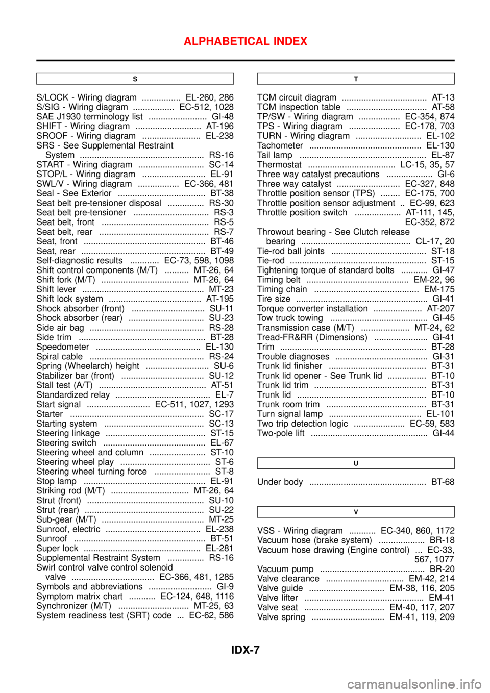
S
S/LOCK - Wiring diagram ................ EL-260, 286
S/SIG - Wiring diagram ................. EC-512, 1028
SAE J1930 terminology list ........................ GI-48
SHIFT - Wiring diagram ........................... AT-196
SROOF - Wiring diagram ........................ EL-238
SRS - See Supplemental Restraint
System ................................................... RS-16
START - Wiring diagram ........................... SC-14
STOP/L - Wiring diagram .......................... EL-91
SWL/V - Wiring diagram ................. EC-366, 481
Seal - See Exterior .................................... BT-38
Seat belt pre-tensioner disposal ............... RS-30
Seat belt pre-tensioner ............................... RS-3
Seat belt, front ............................................ RS-5
Seat belt, rear ............................................. RS-7
Seat, front .................................................. BT-46
Seat, rear ................................................... BT-49
Self-diagnostic results ............ EC-73, 598, 1098
Shift control components (M/T) .......... MT-26, 64
Shift fork (M/T) .................................... MT-26, 64
Shift lever .................................................. MT-23
Shift lock system ...................................... AT-195
Shock absorber (front) .............................. SU-11
Shock absorber (rear) ............................... SU-23
Side air bag ............................................... RS-28
Side trim .................................................... BT-28
Speedometer ........................................... EL-130
Spiral cable ............................................... RS-24
Spring (Wheelarch) height .......................... SU-6
Stabilizer bar (front) .................................. SU-12
Stall test (A/T) ............................................ AT-51
Standardized relay ....................................... EL-7
Start signal .......................... EC-511, 1027, 1293
Starter ....................................................... SC-17
Starting system ......................................... SC-13
Steering linkage ......................................... ST-15
Steering switch .......................................... EL-67
Steering wheel and column ....................... ST-10
Steering wheel play ..................................... ST-6
Steering wheel turning force ....................... ST-8
Stop lamp .................................................. EL-91
Striking rod (M/T) ................................ MT-26, 64
Strut (front) ................................................ SU-10
Strut (rear) ................................................. SU-22
Sub-gear (M/T) .......................................... MT-25
Sunroof, electric ....................................... EL-238
Sunroof ...................................................... BT-51
Super lock ................................................ EL-281
Supplemental Restraint System ............... RS-16
Swirl control valve control solenoid
valve .................................. EC-366, 481, 1285
Symbols and abbreviations .......................... GI-9
Symptom matrix chart ........... EC-124, 648, 1116
Synchronizer (M/T) ............................. MT-25, 63
System readiness test (SRT) code ... EC-62, 586
T
TCM circuit diagram ................................... AT-13
TCM inspection table ................................. AT-58
TP/SW - Wiring diagram ................. EC-354, 874
TPS - Wiring diagram ..................... EC-178, 703
TURN - Wiring diagram ........................... EL-102
Tachometer .............................................. EL-130
Tail lamp .................................................... EL-87
Thermostat .................................... LC-15, 35, 57
Three way catalyst precautions ................... GI-6
Three way catalyst .......................... EC-327, 848
Throttle position sensor (TPS) ........ EC-175, 700
Throttle position sensor adjustment .. EC-99, 623
Throttle position switch ................... AT-111, 145,
EC-352, 872
Throwout bearing - See Clutch release
bearing ............................................. CL-17, 20
Tie-rod ball joints ....................................... ST-18
Tie-rod ........................................................ ST-15
Tightening torque of standard bolts ........... GI-47
Timing belt .......................................... EM-22, 96
Timing chain ........................................... EM-175
Tire size ...................................................... GI-41
Torque converter installation .................... AT-207
Tow truck towing ........................................ GI-45
Transmission case (M/T) .................... MT-24, 62
Tread-FR&RR (Dimensions) ...................... GI-41
Trim ............................................................ BT-28
Trouble diagnoses ...................................... GI-31
Trunk lid finisher ........................................ BT-31
Trunk lid opener - See Trunk lid ................ BT-10
Trunk lid trim .............................................. BT-31
Trunk lid ..................................................... BT-10
Trunk room trim ......................................... BT-31
Turn signal lamp ...................................... EL-101
Two trip detection logic ..................... EC-59, 583
Two-pole lift ................................................ GI-44
U
Under body ................................................ BT-68
V
VSS - Wiring diagram ........... EC-340, 860, 1172
Vacuum hose (brake system) ................... BR-18
Vacuum hose drawing (Engine control) ... EC-33,
567, 1077
Vacuum pump ........................................... BR-20
Valve clearance ................................ EM-42, 214
Valve guide ............................... EM-38, 116, 205
Valve lifter ................................................. EM-41
Valve seat ................................. EM-40, 117, 207
Valve spring .............................. EM-41, 119, 209
ALPHABETICAL INDEX
IDX-7
Page 2703 of 3051

Vehicle speed sensor (VSS) . EC-338, 858, 1172
Viscosity number (SAE) ............................ MA-21
Viscous coupling (FF M/T) ........................ MT-63
W
WARN - Wiring diagram .......................... EL-156
WIP/R - Wiring diagram .......................... EL-184
WIPER - Wiring diagram ......................... EL-178
Warning chime ......................................... EL-165
Warning lamps ......................................... EL-155
Washer, front ........................................... EL-176
Water pump ................................... LC-14, 33, 55
Water temperature gauge ........................ EL-130
Weatherstrip - See Exterior ....................... BT-38
Wheel alignment (rear) ............................. SU-19
Wheel bearing (front) .................................. AX-3Wheel bearing (rear) ................................. AX-22
Wheel hub (front) ........................................ AX-5
Wheel hub (rear) ....................................... AX-23
Wheel sensors (ABS) ............................... BR-90
Wheelarch height ........................................ SU-6
Wheelbase (Dimensions) ........................... GI-41
Wide open & closed throttle position
switch .......................................... EC-175, 700
Width (Dimensions) .................................... GI-41
Window, rear .............................................. BT-59
Windshield ................................................. BT-59
Wiper, front .............................................. EL-176
Wiring diagram (cell code) list ................. EL-525
Wiring diagrams .......................................... GI-11
Withdrawal lever (clutch) ..................... CL-17, 20
Wrist pin - See Piston pin inspection ...... EM-54,
134, 226
ALPHABETICAL INDEX
IDX-8
Page 2718 of 3051

Thermostat
REMOVAL AND INSTALLATIONNLLC0021
SEM861F
Be careful not to spill coolant over engine compartment. Use
a rag to absorb coolant.
1. Drain engine coolant.
Refer to LC-19, ªChanging Engine Coolantº.
2. Remove water inlet, then take out thermostat.
SEM862F
3. Install gum ring to thermostat.
SEM863F
4. Install thermostat with jiggle valve or air bleeder at upper side.
After installation, run engine for a few minutes, and check
for leaks.
ENGINE COOLING SYSTEMQG
Thermostat
LC-15
Page 2738 of 3051

Thermostat
REMOVAL AND INSTALLATIONNLLC0134
SLC267B
Be careful not to spill coolant over engine compartment. Use
a rag to absorb coolant.
1. Drain engine coolant.
2. Remove lower radiator hose.
3. Remove water inlet, then take out thermostat.
SLC767
4. Install thermostat with jiggle valve or air bleeder at upper side.
+Apply a continuous bead of liquid gasket to mating sur-
face of water inlet.
+After installation, run engine for a few minutes, and check
for leaks.
ENGINE COOLING SYSTEMSR
Thermostat
LC-35
Page 2760 of 3051

Thermostat
REMOVAL AND INSTALLATIONNLLC0059
YLC012
+Be careful not to spill coolant over engine compartment.
Use a rag to absorb coolant.
1. Drain engine coolant. Refer to LC-59, ªChanging Engine Cool-
antº.
2. Remove exhaust manifold cover.
3. Remove water inlet.
4. Remove thermostat.
JLC300B
5. Install thermostat with jiggle valve facing upward.
+Carefully install the rubber ring to the flange of the
thermostat, making sure it does not slip out of place.
6. After installation and refilling coolant, run engine for a few
minutes, and check for leaks.
ENGINE COOLING SYSTEMYD
Thermostat
LC-57
Page 3024 of 3051

FRONT & REAR SUSPENSION
SECTION
SU
CONTENTS
FRONT SUSPENSION....................................................2
Precautions ..................................................................2
PRECAUTIONS.........................................................2
Preparation ..................................................................2
SPECIAL SERVICE TOOLS........................................2
COMMERCIAL SERVICE TOOLS................................2
Noise, Vibration and Harshness (NVH)
Troubleshooting ...........................................................4
NVH TROUBLESHOOTING CHART............................4
Components.................................................................5
On-vehicle Service.......................................................6
FRONT SUSPENSION PARTS...................................6
BALANCING WHEELS...............................................6
TIRE ROTATION.......................................................8
FRONT WHEEL ALIGNMENT.....................................8
Coil Spring and Shock Absorber ...............................10
COMPONENTS.......................................................10
REMOVAL AND INSTALLATION............................... 11
DISASSEMBLY........................................................ 11
INSPECTION........................................................... 11
ASSEMBLY.............................................................12
Stabilizer Bar .............................................................12
REMOVAL AND INSTALLATION...............................12
Transverse Link and Lower Ball Joint .......................13
REMOVAL AND INSTALLATION...............................13
INSPECTION...........................................................13
Service Data and Specifications (SDS).....................15
GENERAL SPECIFICATIONS (FRONT).....................15
FRONT WHEEL ALIGNMENT (UNLADEN*1).............15
LOWER BALL JOINT...............................................15
WHEELARCH HEIGHT (UNLADEN*1).......................16
WHEEL RUNOUT....................................................16
WHEEL BALANCE...................................................16
REAR SUSPENSION.....................................................17
Precautions ................................................................17
PRECAUTIONS.......................................................17
Preparation ................................................................17
COMMERCIAL SERVICE TOOLS..............................17
Noise, Vibration and Harshness (NVH)
Troubleshooting .........................................................17
Components...............................................................18
On-vehicle Service.....................................................19
REAR SUSPENSION PARTS...................................19
REAR WHEEL ALIGNMENT.....................................19
Removal and Installation ...........................................22
REMOVAL...............................................................23
INSTALLATION........................................................23
Coil Spring and Shock Absorber ...............................23
REMOVAL AND INSTALLATION...............................23
DISASSEMBLY........................................................24
INSPECTION...........................................................24
ASSEMBLY.............................................................24
Torsion Beam, Lateral Link and Control Rod ............25
DISASSEMBLY........................................................25
INSPECTION...........................................................25
ASSEMBLY.............................................................25
Service Data and Specifications (SDS).....................27
GENERAL SPECIFICATIONS (REAR).......................27
REAR WHEEL ALIGNMENT (UNLADEN*).................27
Page 3027 of 3051

Noise, Vibration and Harshness (NVH)
Troubleshooting
=NLSU0004NVH TROUBLESHOOTING CHARTNLSU0004S01Use the chart below to help you find the cause of the symptom. If necessary, repair or replace these parts.
Reference page
SU-5, 18
SU-11, 23
—
—
—
SU-10, 22
SU-8
SU-12
SU-8
—
—
—
—
—
—
AX-10
AX-3, AX-22
Refer to SUSPENSION
in this chart.
Refer to TIRES
in this chart.
Refer to ROAD WHEEL
in this chart.
BR-6
ST-5
Possible Cause
and SUSPECTED
PA R T S
Improper installation, looseness
Shock absorber deformation,
damage or deflection
Bushing or mounting deterioration
Parts interference
Spring fatigue
Suspension looseness
Incorrect wheel alignment
Stabilizer bar fatigue
Out-of-round
Imbalance
Incorrect air pressure
Uneven tire wear
Deformation or damage
Non-uniformity
Incorrect tire size
DRIVE SHAFT
AXLE
SUSPENSION
TIRES
ROAD WHEEL
BRAKES
STEERING Symptom
SUSPENSION
Noise× × ×××× ×× × × ××
Shake× × ×× × ×× × × ××
Vibration× × ××× ×× × ×
Shimmy×××× × × × ×××
Judder××× × × ×××
Poor quality
ride or han-
dling× × ××× ×× × × ×
TIRES
Noise× ×××××× ×× × × ××
Shake× ××××× ××× × × ××
Vibration× ××× × ×
Shimmy× ××××××× × × × ××
Judder× ××××× × × × × ××
Poor quality
ride or han-
dling× ××××× × × × ×
ROAD WHEEL
Noise× ×××××××××
Shake× ×××××××××
Shimmy,
Judder×××××××××
Poor quality
ride or han-
dling×××××××
×: Applicable
FRONT SUSPENSION
Noise, Vibration and Harshness (NVH) Troubleshooting
SU-4
Page 3029 of 3051

SMA525A
On-vehicle Service
FRONT SUSPENSION PARTSNLSU0006Check front axle and front suspension parts for excessive play,
cracks, wear or other damage.
+Shake each front wheel to check for excessive play.
+Make sure that cotter pin is inserted.
+Retighten all axle and suspension nuts and bolts to the speci-
fied torque.
Tightening torque:
Refer to “FRONT SUSPENSION”, SU-5.
SFA392B
+Check strut (shock absorber) for oil leakage or other damage.
+Check suspension ball joint for grease leakage and ball joint
dust cover for cracks or other damage.
If ball joint dust cover is cracked or damaged, replace trans-
verse link.
SFA818AA
+Check spring height from top of wheelarch to the ground.
a) Vehicle must be unladen*, parked on a level surface, and tires
checked for proper inflation and wear (tread wear indicator
must not be showing).
*: Fuel, radiator coolant and engine oil full. Spare tire, jack,
hand tools and mats in designated positions.
b) Bounce vehicle up and down several times before measuring.
Standard height: Refer to SDS, SU-16.
c) Spring height is not adjustable. If out of specification, check for
worn springs or suspension parts.
SSU031
+Check suspension ball joint end play.
a) Jack up front of vehicle and set the stands.
b) Clamp dial indicator onto transverse link and place indicator tip
on lower edge of brake caliper.
c) Make sure front wheels are straight and brake pedal is
depressed.
d) Place a pry bar between transverse link and inner rim of road
wheel.
e) While raising and releasing pry bar, observe maximum dial
indicator value.
Vertical end play: 0 mm (0 in)
f) If ball joint movement is beyond specifications, remove and
replace it.
BALANCING WHEELSNLSU0042+Adjust wheel balance using road wheel center.
Wheel balance (Maximum allowable unbalance):
Refer to SDS, SU-16.
FRONT SUSPENSION
On-vehicle Service
SU-6
Page 3030 of 3051

SFA975B
Preliminary InspectionNLSU0042S01Aluminum wheelNLSU0042S01011. Check tires for wear and improper inflation.
2. Check wheels for deformation, cracks and other damage.
If deformed, remove wheel and check wheel runout.
a. Remove tire from aluminum wheel and mount on a tire balance
machine.
b. Set dial indicator as shown in the illustration.
Wheel runout (Dial indicator value):
Refer to SDS, SU-16.
3. Check front wheel bearings for looseness.
4. Check front suspension for looseness.
5. Check steering linkage for looseness.
6. Check that front shock absorbers work properly.
7. Check vehicle posture (Unladen).
SFA981B
Steel wheelNLSU0042S01021. Check tires for wear and improper inflation.
2. Check wheels for deformation, cracks and other damage.
If deformed, remove wheel and check wheel runout.
a. Remove tire from steel wheel and mount wheel on a tire bal-
ance machine.
b. Set two dial indicators as shown in the illustration.
c. Set each dial indicator to 0.
d. Rotate wheel and check dial indicators at several points
around the circumference of the wheel.
e. Calculate runout at each point as shown below.
Radial runout = (A + B)/2
Lateral runout = (C + D)/2
f. Select maximum positive runout value and the maximum
negative value.
Add the two values to determine total runout.
In case a positive or negative value is not available, use the
maximum value (negative or positive) for total runout.
If the total runout value exceeds the limit, replace steel wheel.
Wheel runout:
Refer to SDS, SU-16.
3. Check front wheel bearings for looseness.
4. Check front suspension for looseness.
5. Check steering linkage for looseness.
6. Check that front shock absorbers work properly.
7. Check vehicle posture (Unladen).
FRONT SUSPENSION
On-vehicle Service (Cont’d)
SU-7