heating NISSAN ALMERA TINO 2001 Service Repair Manual
[x] Cancel search | Manufacturer: NISSAN, Model Year: 2001, Model line: ALMERA TINO, Model: NISSAN ALMERA TINO 2001Pages: 3051, PDF Size: 46.38 MB
Page 52 of 3051
SAT767B
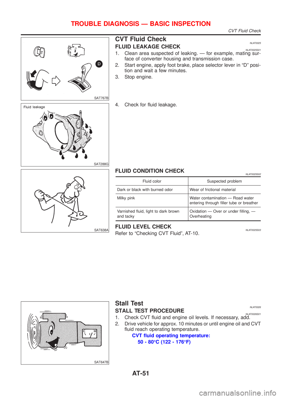
CVT Fluid CheckNLAT0025FLUID LEAKAGE CHECKNLAT0025S011. Clean area suspected of leaking. Ð for example, mating sur-
face of converter housing and transmission case.
2. Start engine, apply foot brake, place selector lever in ªDº posi-
tion and wait a few minutes.
3. Stop engine.
SAT288G
4. Check for fluid leakage.
SAT638A
FLUID CONDITION CHECKNLAT0025S02
Fluid color Suspected problem
Dark or black with burned odor Wear of frictional material
Milky pink Water contamination Ð Road water
entering through filler tube or breather
Varnished fluid, light to dark brown
and tackyOxidation Ð Over or under filling, Ð
Overheating
FLUID LEVEL CHECKNLAT0025S03Refer to ªChecking CVT Fluidº, AT-10.
SAT647B
Stall TestNLAT0026STALL TEST PROCEDURENLAT0026S011. Check CVT fluid and engine oil levels. If necessary, add.
2. Drive vehicle for approx. 10 minutes or until engine oil and CVT
fluid reach operating temperature.
CVT fluid operating temperature:
50 - 80ÉC (122 - 176ÉF)
TROUBLE DIAGNOSIS Ð BASIC INSPECTION
CVT Fluid Check
AT-51
Page 430 of 3051
CONSULT-II Reference Value in Data Monitor
Mode ........................................................................373
ECM Terminals and Reference Value .....................374
On Board Diagnosis Logic.......................................374
Overall Function Check ...........................................375
Wiring Diagram ........................................................376
Diagnostic Procedure ..............................................378
Main 12 Causes of Overheating..............................384
Component Inspection .............................................384
DTC P1401 EGR TEMPERATURE SENSOR
(WHERE FITTED)........................................................386
Component Description ...........................................386
On Board Diagnosis Logic.......................................386
DTC Confirmation Procedure ..................................386
Wiring Diagram ........................................................389
Diagnostic Procedure ..............................................391
Component Inspection .............................................392
DTC P1402 EGR FUNCTION (OPEN) (WHERE
FITTED)........................................................................393
Description ...............................................................393
CONSULT-II Reference Value in Data Monitor
Mode ........................................................................394
ECM Terminals and Reference Value .....................394
On Board Diagnosis Logic.......................................394
DTC Confirmation Procedure ..................................395
Wiring Diagram ........................................................397
Diagnostic Procedure ..............................................399
Component Inspection .............................................400
DTC P1706 PARK/NEUTRAL POSITION (PNP)
SWITCH.......................................................................402
Component Description ...........................................402
CONSULT-II Reference Value in Data Monitor
Mode ........................................................................402
ECM Terminals and Reference Value .....................402
On Board Diagnosis Logic.......................................402
DTC Confirmation Procedure ..................................402
Overall Function Check ...........................................403
Wiring Diagram ........................................................404
Diagnostic Procedure ..............................................405
INTAKE AIR TEMPERATURE SENSOR....................407
Component Description ...........................................407
Wiring Diagram ........................................................409
Diagnostic Procedure .............................................. 411
Component Inspection .............................................413
HEATED OXYGEN SENSOR 1 (FRONT)...................414
Component Description ...........................................414
CONSULT-II Reference Value in Data Monitor
Mode ........................................................................414
ECM Terminals and Reference Value .....................414
Wiring Diagram ........................................................415
Diagnostic Procedure ..............................................417
Component Inspection .............................................419HEATED OXYGEN SENSOR 1 HEATER (FRONT)...421
Description ...............................................................421
CONSULT-II Reference Value in Data Monitor
Mode ........................................................................421
ECM Terminals and Reference Value .....................421
Wiring Diagram ........................................................422
Diagnostic Procedure ..............................................424
Component Inspection .............................................425
HEATED OXYGEN SENSOR 2 (REAR).....................426
Component Description ...........................................426
CONSULT-II Reference Value in Data Monitor
Mode ........................................................................426
ECM Terminals and Reference Value .....................426
Wiring Diagram ........................................................427
Diagnostic Procedure ..............................................429
Component Inspection .............................................431
HEATED OXYGEN SENSOR 2 HEATER (REAR).....433
Description ...............................................................433
CONSULT-II Reference Value in Data Monitor
Mode ........................................................................433
ECM Terminals and Reference Value .....................433
Wiring Diagram ........................................................434
Diagnostic Procedure ..............................................436
Component Inspection .............................................438
CRANKSHAFT POSITION SENSOR (POS)...............439
Component Description ...........................................439
ECM Terminals and Reference Value .....................439
Wiring Diagram ........................................................440
Diagnostic Procedure ..............................................442
Component Inspection .............................................445
EGR VOLUME CONTROL SYSTEM (WHERE
FITTED)........................................................................446
Description ...............................................................446
CONSULT-II Reference Value in Data Monitor
Mode ........................................................................447
ECM Terminals and Reference Value .....................448
Wiring Diagram ........................................................449
Diagnostic Procedure ..............................................451
Component Inspection .............................................456
EVAP CANISTER PURGE VOLUME CONTROL
SOLENOID VALVE......................................................458
Description ...............................................................458
CONSULT-II Reference Value in Data Monitor
Mode ........................................................................458
ECM Terminals and Reference Value .....................459
Wiring Diagram ........................................................460
Diagnostic Procedure ..............................................462
Component Inspection .............................................465
IDLE AIR CONTROL VALVE (IACV) - AUXILIARY
AIR CONTROL (AAC) VALVE....................................466
Description ...............................................................466
CONTENTS(Cont'd)
EC-5
Page 435 of 3051
Component Inspection .............................................847
DTC P0420 THREE WAY CATALYST FUNCTION...848
On Board Diagnosis Logic.......................................848
DTC Confirmation Procedure ..................................848
Overall Function Check ...........................................849
Diagnostic Procedure ..............................................849
DTC P0443 EVAP CANISTER PURGE VOLUME
CONTROL SOLENOID VALVE (CIRCUIT).................852
Description ...............................................................852
CONSULT-II Reference Value in Data Monitor
Mode ........................................................................852
ECM Terminals and Reference Value .....................853
On Board Diagnosis Logic.......................................853
DTC Confirmation Procedure ..................................853
Wiring Diagram ........................................................854
Diagnostic Procedure ..............................................856
Component Inspection .............................................857
DTC P0500 VEHICLE SPEED SENSOR (VSS).........858
Component Description ...........................................858
ECM Terminals and Reference Value .....................858
On Board Diagnosis Logic.......................................858
DTC Confirmation Procedure ..................................858
Wiring Diagram ........................................................860
Diagnostic Procedure ..............................................862
DTC P0505 IDLE AIR CONTROL VALVE (IACV) -
AUXILIARY AIR CONTROL (AAC) VALVE...............863
Description ...............................................................863
CONSULT-II Reference Value in Data Monitor
Mode ........................................................................864
ECM Terminals and Reference Value .....................864
On Board Diagnosis Logic.......................................864
DTC Confirmation Procedure ..................................864
Wiring Diagram ........................................................865
Diagnostic Procedure ..............................................867
Component Inspection .............................................871
DTC P0510 CLOSED THROTTLE POSITION
SWITCH.......................................................................872
Component Description ...........................................872
CONSULT-II Reference Value in Data Monitor
Mode ........................................................................872
ECM Terminals and Reference Value .....................872
On Board Diagnosis Logic.......................................872
DTC Confirmation Procedure ..................................872
Overall Function Check ...........................................873
Wiring Diagram ........................................................874
Diagnostic Procedure ..............................................876
Component Inspection .............................................878
DTC P0605 ECM.........................................................880
Component Description ...........................................880
On Board Diagnosis Logic.......................................880
DTC Confirmation Procedure ..................................880
Diagnostic Procedure ..............................................881DTC P1217 OVERHEAT (COOLING SYSTEM).........882
System Description ..................................................882
CONSULT-II Reference Value in Data Monitor
Mode ........................................................................882
ECM Terminals and Reference Value .....................883
On Board Diagnosis Logic.......................................883
Overall Function Check ...........................................884
Wiring Diagram ........................................................885
Diagnostic Procedure ..............................................887
Main 12 Causes of Overheating..............................898
Component Inspection .............................................898
DTC P1320 IGNITION SIGNAL...................................900
Component Description ...........................................900
CONSULT-II Reference Value in Data Monitor
Mode ........................................................................900
ECM Terminals and Reference Value .....................900
On Board Diagnosis Logic.......................................901
DTC Confirmation Procedure ..................................901
Wiring Diagram ........................................................903
Diagnostic Procedure ..............................................905
Component Inspection .............................................907
DTC P1336 CRANKSHAFT POSITION SENSOR
(CKPS) (OBD) (COG)..................................................909
Component Description ...........................................909
ECM Terminals and Reference Value .....................909
On Board Diagnosis Logic.......................................910
DTC Confirmation Procedure ..................................910
Wiring Diagram ........................................................ 911
Diagnostic Procedure ..............................................913
Component Inspection .............................................914
DTC P1401 EGR TEMPERATURE SENSOR
(WHERE FITTED)........................................................915
Component Description ...........................................915
On Board Diagnosis Logic.......................................915
DTC Confirmation Procedure ..................................915
Wiring Diagram ........................................................918
Diagnostic Procedure ..............................................919
Component Inspection .............................................920
DTC P1402 EGR FUNCTION (OPEN) (WHERE
FITTED)........................................................................921
Description ...............................................................921
CONSULT-II Reference Value in Data Monitor
Mode ........................................................................922
ECM Terminals and Reference Value .....................922
On Board Diagnosis Logic.......................................922
DTC Confirmation Procedure ..................................923
Wiring Diagram ........................................................925
Diagnostic Procedure ..............................................926
DTC P1605 A/T DIAGNOSIS COMMUNICATION
LINE.............................................................................928
System Description ..................................................928
ECM Terminals and Reference Value .....................928
CONTENTS(Cont'd)
EC-10
Page 438 of 3051
TROUBLE DIAGNOSIS - INTRODUCTION.............. 1107
Introduction ............................................................ 1107
Work Flow .............................................................. 1109
TROUBLE DIAGNOSIS - BASIC INSPECTION.......1111
Basic Inspection.....................................................1111
TROUBLE DIAGNOSIS - GENERAL
DESCRIPTION........................................................... 1116
Symptom Matrix Chart ........................................... 1116
CONSULT-II Reference Value in Data Monitor
Mode ...................................................................... 1126
Major Sensor Reference Graph in Data Monitor
Mode ...................................................................... 1128
ECM Terminals and Reference Value ................... 1129
TROUBLE DIAGNOSIS FOR INTERMITTENT
INCIDENT................................................................... 1135
Description ............................................................. 1135
Diagnostic Procedure ............................................ 1135
TROUBLE DIAGNOSIS FOR POWER SUPPLY...... 1136
Main Power Supply and Ground Circuit ................ 1136
DTC P0100 MASS AIR FLOW SEN......................... 1143
Component Description ......................................... 1143
CONSULT-II Reference Value in Data Monitor
Mode ...................................................................... 1143
ECM Terminals and Reference Value ................... 1143
On Board Diagnosis Logic..................................... 1143
DTC Confirmation Procedure ................................ 1144
Wiring Diagram ...................................................... 1145
Diagnostic Procedure ............................................ 1147
DTC P0115 COOLANT TEMP SEN.......................... 1150
Description ............................................................. 1150
On Board Diagnosis Logic..................................... 1150
DTC Confirmation Procedure ................................ 1150
Wiring Diagram ...................................................... 1152
Diagnostic Procedure ............................................ 1153
DTC P0120 ACCEL POS SENSOR.......................... 1155
Description ............................................................. 1155
CONSULT-II Reference Value in Data Monitor
Mode ...................................................................... 1155
ECM Terminals and Reference Value ................... 1155
On Board Diagnosis Logic..................................... 1156
DTC Confirmation Procedure ................................ 1156
Wiring Diagram ...................................................... 1157
Diagnostic Procedure ............................................ 1159
DTC P0335 CRANK POS SEN (TDC)...................... 1166
Description ............................................................. 1166
CONSULT-II Reference Value in Data Monitor
Mode ...................................................................... 1166
ECM Terminals and Reference Value ................... 1166
On Board Diagnosis Logic..................................... 1166
DTC Confirmation Procedure ................................ 1167
Wiring Diagram ...................................................... 1168
Diagnostic Procedure ............................................ 1169DTC P0500 VEHICLE SPEED SEN.......................... 1172
Description ............................................................. 1172
ECM Terminals and Reference Value ................... 1172
On Board Diagnosis Logic..................................... 1172
Overall Function Check ......................................... 1172
Wiring Diagram ...................................................... 1174
Diagnostic Procedure ............................................ 1176
DTC P0571 BRAKE SW............................................ 1177
Description ............................................................. 1177
ECM Terminals and Reference Value ................... 1177
On Board Diagnosis Logic..................................... 1177
DTC Confirmation Procedure ................................ 1177
Wiring Diagram ...................................................... 1179
Diagnostic Procedure ............................................ 1181
DTC P1107 ECM 10.................................................. 1185
Description ............................................................. 1185
On Board Diagnosis Logic..................................... 1185
DTC Confirmation Procedure ................................ 1185
Diagnostic Procedure ............................................ 1186
DTC P1180 P9.FUEL TEMP SEN............................. 1187
Description ............................................................. 1187
CONSULT-II Reference Value in Data Monitor
Mode ...................................................................... 1187
ECM Terminals and Reference Value ................... 1188
On Board Diagnosis Logic..................................... 1188
DTC Confirmation Procedure ................................ 1188
Wiring Diagram ...................................................... 1190
Diagnostic Procedure ............................................ 1192
DTC P1202 FUEL CUT SYSTEM2........................... 1194
Description ............................................................. 1194
CONSULT-II Reference Value in Data Monitor
Mode ...................................................................... 1194
ECM Terminals and Reference Value ................... 1195
On Board Diagnosis Logic..................................... 1195
DTC Confirmation Procedure ................................ 1195
Wiring Diagram ...................................................... 1197
Diagnostic Procedure ............................................ 1199
DTC P1217 OVER HEAT..........................................1201
Description .............................................................1201
CONSULT-II Reference Value in Data Monitor
Mode ......................................................................1201
ECM Terminals and Reference Value ...................1201
On Board Diagnosis Logic.....................................1202
Overall Function Check .........................................1203
Wiring Diagram ......................................................1204
Diagnostic Procedure ............................................1206
Main 12 Causes of Overheating............................1217
DTC P1241 P7.F/INJ TIMG FB.................................1218
Description .............................................................1218
CONSULT-II Reference Value in Data Monitor
Mode ......................................................................1218
ECM Terminals and Reference Value ...................1219
CONTENTS(Cont'd)
EC-13
Page 710 of 3051
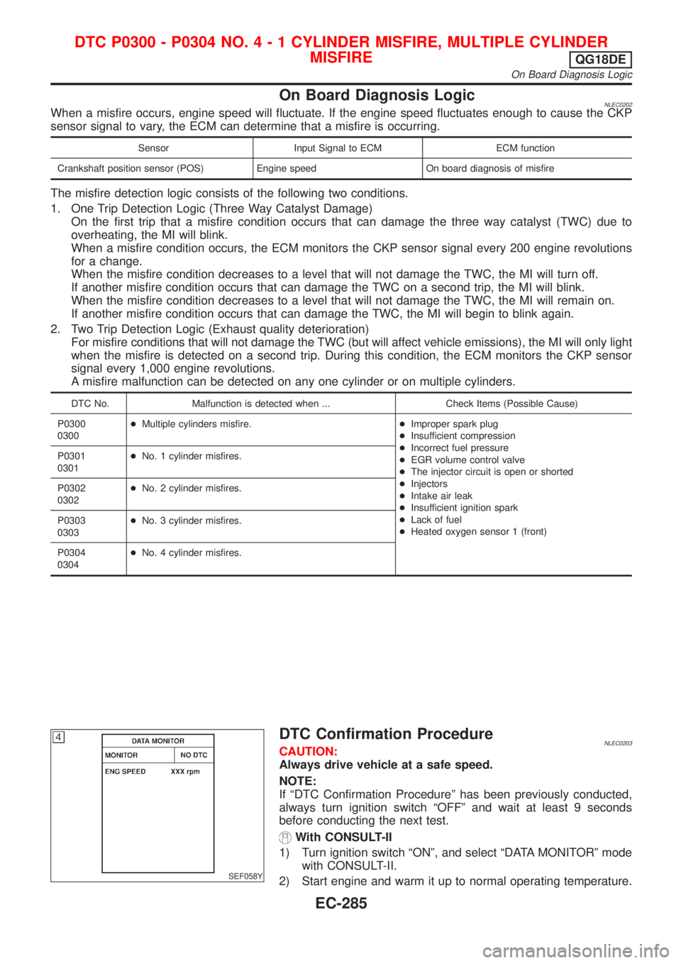
On Board Diagnosis LogicNLEC0202When a misfire occurs, engine speed will fluctuate. If the engine speed fluctuates enough to cause the CKP
sensor signal to vary, the ECM can determine that a misfire is occurring.
Sensor Input Signal to ECM ECM function
Crankshaft position sensor (POS) Engine speed On board diagnosis of misfire
The misfire detection logic consists of the following two conditions.
1. One Trip Detection Logic (Three Way Catalyst Damage)
On the first trip that a misfire condition occurs that can damage the three way catalyst (TWC) due to
overheating, the MI will blink.
When a misfire condition occurs, the ECM monitors the CKP sensor signal every 200 engine revolutions
for a change.
When the misfire condition decreases to a level that will not damage the TWC, the MI will turn off.
If another misfire condition occurs that can damage the TWC on a second trip, the MI will blink.
When the misfire condition decreases to a level that will not damage the TWC, the MI will remain on.
If another misfire condition occurs that can damage the TWC, the MI will begin to blink again.
2. Two Trip Detection Logic (Exhaust quality deterioration)
For misfire conditions that will not damage the TWC (but will affect vehicle emissions), the MI will only light
when the misfire is detected on a second trip. During this condition, the ECM monitors the CKP sensor
signal every 1,000 engine revolutions.
A misfire malfunction can be detected on any one cylinder or on multiple cylinders.
DTC No. Malfunction is detected when ... Check Items (Possible Cause)
P0300
0300+Multiple cylinders misfire.+Improper spark plug
+Insufficient compression
+Incorrect fuel pressure
+EGR volume control valve
+The injector circuit is open or shorted
+Injectors
+Intake air leak
+Insufficient ignition spark
+Lack of fuel
+Heated oxygen sensor 1 (front) P0301
0301+No. 1 cylinder misfires.
P0302
0302+No. 2 cylinder misfires.
P0303
0303+No. 3 cylinder misfires.
P0304
0304+No. 4 cylinder misfires.
SEF058Y
DTC Confirmation ProcedureNLEC0203CAUTION:
Always drive vehicle at a safe speed.
NOTE:
If ªDTC Confirmation Procedureº has been previously conducted,
always turn ignition switch ªOFFº and wait at least 9 seconds
before conducting the next test.
With CONSULT-II
1) Turn ignition switch ªONº, and select ªDATA MONITORº mode
with CONSULT-II.
2) Start engine and warm it up to normal operating temperature.
DTC P0300 - P0304 NO.4-1CYLINDER MISFIRE, MULTIPLE CYLINDER
MISFIRE
QG18DE
On Board Diagnosis Logic
EC-285
Page 799 of 3051
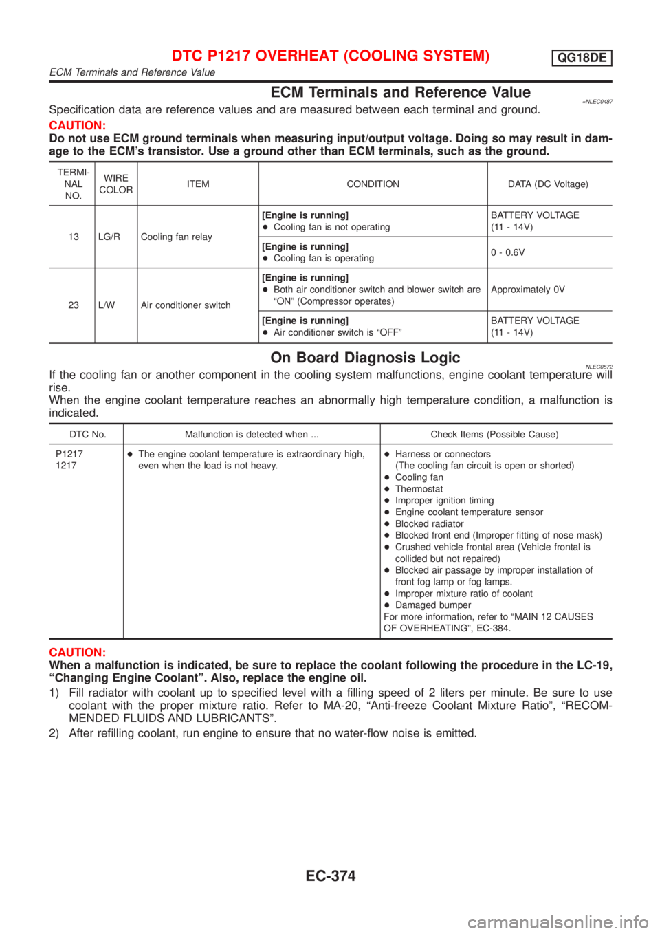
ECM Terminals and Reference Value=NLEC0487Specification data are reference values and are measured between each terminal and ground.
CAUTION:
Do not use ECM ground terminals when measuring input/output voltage. Doing so may result in dam-
age to the ECM's transistor. Use a ground other than ECM terminals, such as the ground.
TERMI-
NAL
NO.WIRE
COLORITEM CONDITION DATA (DC Voltage)
13 LG/R Cooling fan relay[Engine is running]
+Cooling fan is not operatingBATTERY VOLTAGE
(11 - 14V)
[Engine is running]
+Cooling fan is operating0 - 0.6V
23 L/W Air conditioner switch[Engine is running]
+Both air conditioner switch and blower switch are
ªONº (Compressor operates)Approximately 0V
[Engine is running]
+Air conditioner switch is ªOFFºBATTERY VOLTAGE
(11 - 14V)
On Board Diagnosis LogicNLEC0572If the cooling fan or another component in the cooling system malfunctions, engine coolant temperature will
rise.
When the engine coolant temperature reaches an abnormally high temperature condition, a malfunction is
indicated.
DTC No. Malfunction is detected when ... Check Items (Possible Cause)
P1217
1217+The engine coolant temperature is extraordinary high,
even when the load is not heavy.+Harness or connectors
(The cooling fan circuit is open or shorted)
+Cooling fan
+Thermostat
+Improper ignition timing
+Engine coolant temperature sensor
+Blocked radiator
+Blocked front end (Improper fitting of nose mask)
+Crushed vehicle frontal area (Vehicle frontal is
collided but not repaired)
+Blocked air passage by improper installation of
front fog lamp or fog lamps.
+Improper mixture ratio of coolant
+Damaged bumper
For more information, refer to ªMAIN 12 CAUSES
OF OVERHEATINGº, EC-384.
CAUTION:
When a malfunction is indicated, be sure to replace the coolant following the procedure in the LC-19,
ªChanging Engine Coolantº. Also, replace the engine oil.
1) Fill radiator with coolant up to specified level with a filling speed of 2 liters per minute. Be sure to use
coolant with the proper mixture ratio. Refer to MA-20, ªAnti-freeze Coolant Mixture Ratioº, ªRECOM-
MENDED FLUIDS AND LUBRICANTSº.
2) After refilling coolant, run engine to ensure that no water-flow noise is emitted.
DTC P1217 OVERHEAT (COOLING SYSTEM)QG18DE
ECM Terminals and Reference Value
EC-374
Page 808 of 3051
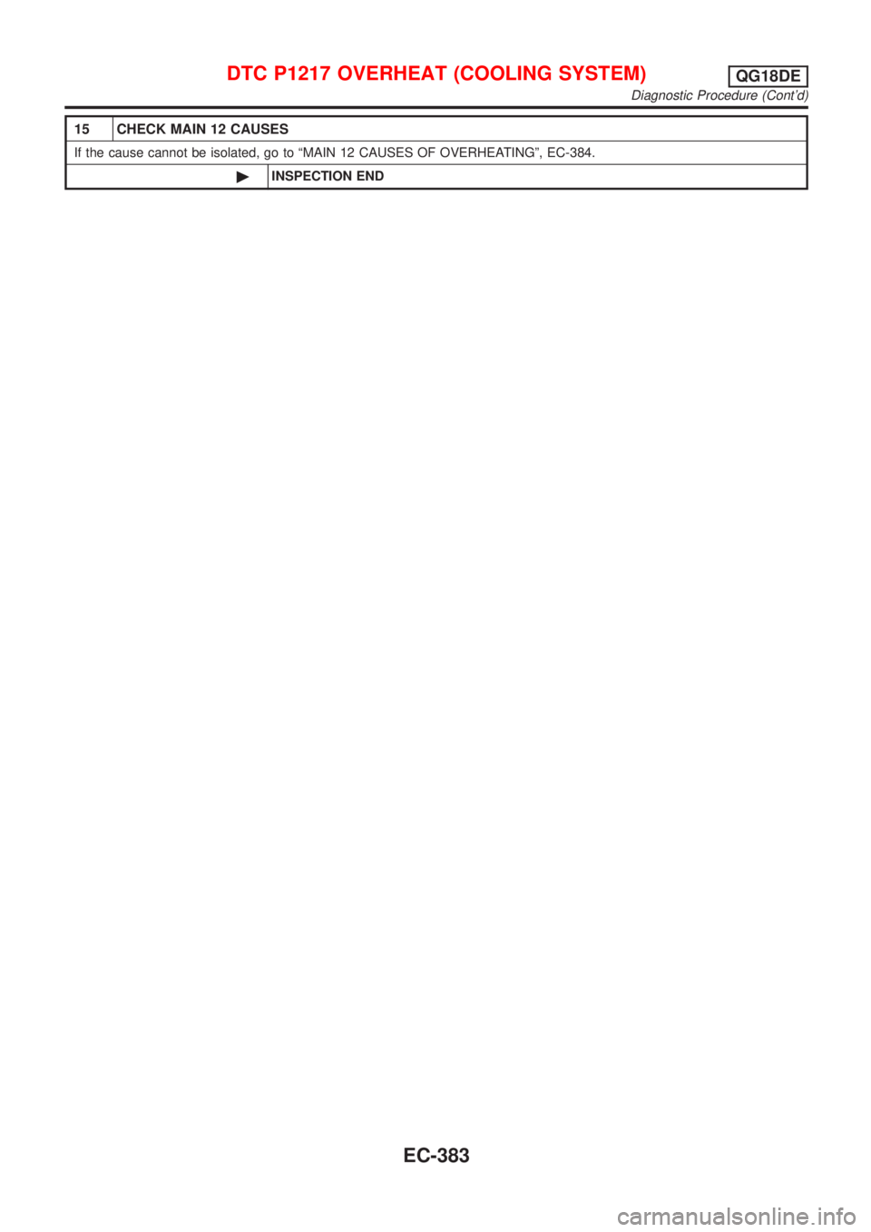
15 CHECK MAIN 12 CAUSES
If the cause cannot be isolated, go to ªMAIN 12 CAUSES OF OVERHEATINGº, EC-384.
©INSPECTION END
DTC P1217 OVERHEAT (COOLING SYSTEM)QG18DE
Diagnostic Procedure (Cont'd)
EC-383
Page 809 of 3051
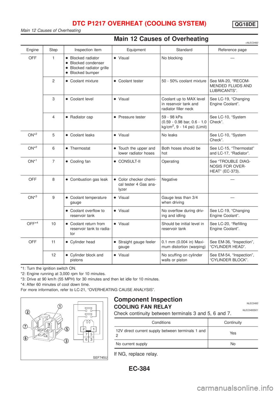
Main 12 Causes of Overheating=NLEC0492
Engine Step Inspection item Equipment Standard Reference page
OFF 1+Blocked radiator
+Blocked condenser
+Blocked radiator grille
+Blocked bumper+Visual No blocking Ð
2+Coolant mixture+Coolant tester 50 - 50% coolant mixture See MA-20, ªRECOM-
MENDED FLUIDS AND
LUBRICANTSº.
3+Coolant level+Visual Coolant up to MAX level
in reservoir tank and
radiator filler neckSee LC-19, ªChanging
Engine Coolantº.
4+Radiator cap+Pressure tester 59 - 98 kPa
(0.59 - 0.98 bar, 0.6 - 1.0
kg/cm
2,9-14psi) (Limit)See LC-10, ªSystem
Checkº.
ON*
25+Coolant leaks+Visual No leaks See LC-10, ªSystem
Checkº.
ON*
26+Thermostat+Touch the upper and
lower radiator hosesBoth hoses should be
hotSee LC-15, ªThermostatº
and LC-17, ªRadiatorº.
ON*
17+Cooling fan+CONSULT-II Operating See ªTROUBLE DIAG-
NOSIS FOR OVER-
HEATº (EC-373).
OFF 8+Combustion gas leak+Color checker chemi-
cal tester 4 Gas ana-
lyzerNegative Ð
ON*
39+Coolant temperature
gauge+Visual Gauge less than 3/4
when drivingÐ
+Coolant overflow to
reservoir tank+Visual No overflow during driv-
ing and idlingSee LC-19, ªChanging
Engine Coolantº.
OFF*
410+Coolant return from
reservoir tank to radia-
tor+Visual Should be initial level in
reservoir tankSee LC-20, ªRefilling
Engine Coolantº.
OFF 11+Cylinder head+Straight gauge feeler
gauge0.1 mm (0.004 in) Maxi-
mum distortion (warping)See EM-36, ªInspectionº,
ªCYLINDER HEADº.
12+Cylinder block and
pistons+Visual No scuffing on cylinder
walls or pistonSee EM-54, ªInspectionº,
ªCYLINDER BLOCKº.
*1: Turn the ignition switch ON.
*2: Engine running at 3,000 rpm for 10 minutes.
*3: Drive at 90 km/h (55 MPH) for 30 minutes and then let idle for 10 minutes.
*4: After 60 minutes of cool down time.
For more information, refer to LC-21, ªOVERHEATING CAUSE ANALYSISº.
SEF745U
Component InspectionNLEC0493COOLING FAN RELAYNLEC0493S01Check continuity between terminals 3 and 5, 6 and 7.
Conditions Continuity
12V direct current supply between terminals 1 and
2Ye s
No current supply No
If NG, replace relay.
DTC P1217 OVERHEAT (COOLING SYSTEM)QG18DE
Main 12 Causes of Overheating
EC-384
Page 1233 of 3051
On Board Diagnosis LogicNLEC1752When a misfire occurs, engine speed will fluctuate (vary). If the engine speed fluctuates enough to cause the
CKP sensor to vary, ECM can detect a misfire.
Sensor Input Signal to ECM ECM function
Crankshaft position sensor (OBD) Engine speed On board diagnosis of misfire
The misfire detection logic consists of the following two conditions.
1. One Trip Detection Logic (Three Way Catalyst Damage)
On the first rip that a misfire condition occurs that can damage the three way catalyst (TWC) due to
overheating, the MI will blink.
When a misfire condition occurs, the ECM monitors the CKP sensor (OBD) signal every 200 engine revo-
lutions for a change.
When the misfire condition decreases to a level that will not damage the TWC, the MI will turn off.
If another misfire condition occurs that can damage the TWC on a second trip, the MI will blink.
When the misfire condition decreases to a level that will not damage the TWC, the MI will remain on.
If another misfire condition occurs that can damage the TWC, the MI will begin to blink again.
2. Two Trip Detection Logic (Exhaust quality deterioration)
For misfire conditions that will not cause damage to the TWC (but will affect vehicle emissions), the MI
will only light when the misfire is detected on a second trip. During this condition, the ECM monitors the
CKP sensor (OBD) signal every 1,000 engine revolutions.
A misfire malfunction can be detected on any one cylinder or on-multiple cylinders.
DTC No. Malfunction is detected when ... Check Items (Possible Cause)
P0300+Multiple cylinders misfire.+Improper spark plug
+Insufficient compression
+Incorrect fuel pressure
+EGR volume control valve
+The injector circuit is open or shorted
+Injectors
+Intake air leak
+The ignition secondary circuit is open or shorted
+Lack of fuel
+Drive plate
+Heated oxygen sensor 1 (front)
+Incorrect distributor roter P0301+No. 1 cylinder misfires.
P0302+No. 2 cylinder misfires.
P0303+No. 3 cylinder misfires.
P0304+No. 4 cylinder misfires.
SEF058Y
DTC Confirmation ProcedureNLEC1522CAUTION:
Always drive vehicle at a safe speed.
NOTE:
If ªDTC Confirmation Procedureº has been previously conducted,
always turn ignition switch ªOFFº and wait at least 10 seconds
before conducting the next test.
With CONSULT-II
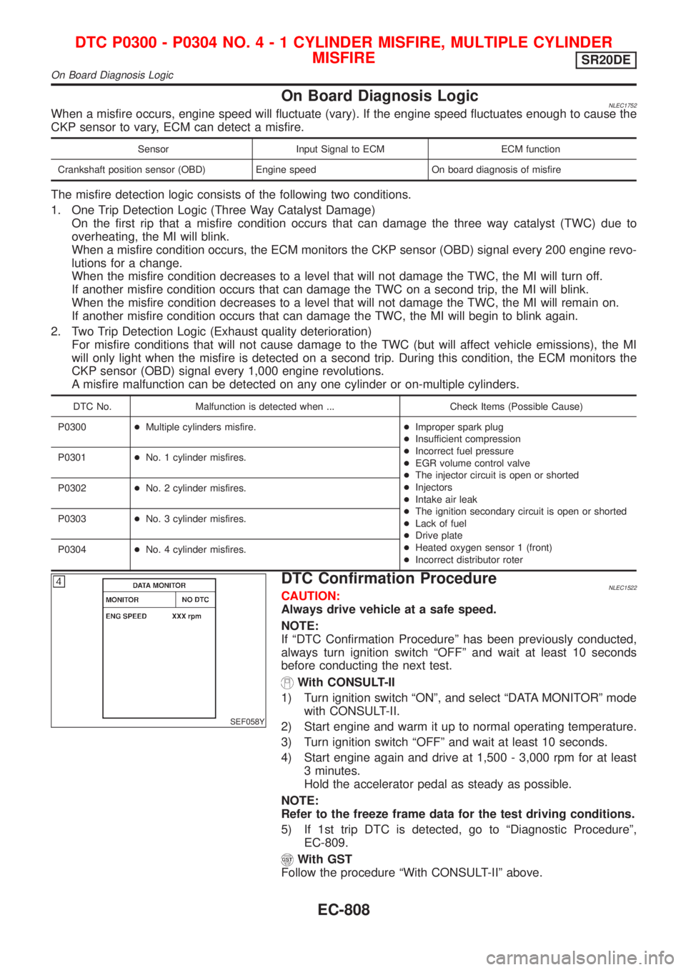
1) Turn ignition switch ªONº, and select ªDATA MONITORº mode
with CONSULT-II.
2) Start engine and warm it up to normal operating temperature.
3) Turn ignition switch ªOFFº and wait at least 10 seconds.
4) Start engine again and drive at 1,500 - 3,000 rpm for at least
3 minutes.
Hold the accelerator pedal as steady as possible.
NOTE:
Refer to the freeze frame data for the test driving conditions.
5) If 1st trip DTC is detected, go to ªDiagnostic Procedureº,
EC-809.
With GST
Follow the procedure ªWith CONSULT-IIº above.
DTC P0300 - P0304 NO.4-1CYLINDER MISFIRE, MULTIPLE CYLINDER
MISFIRE
SR20DE
On Board Diagnosis Logic
EC-808
Page 1308 of 3051
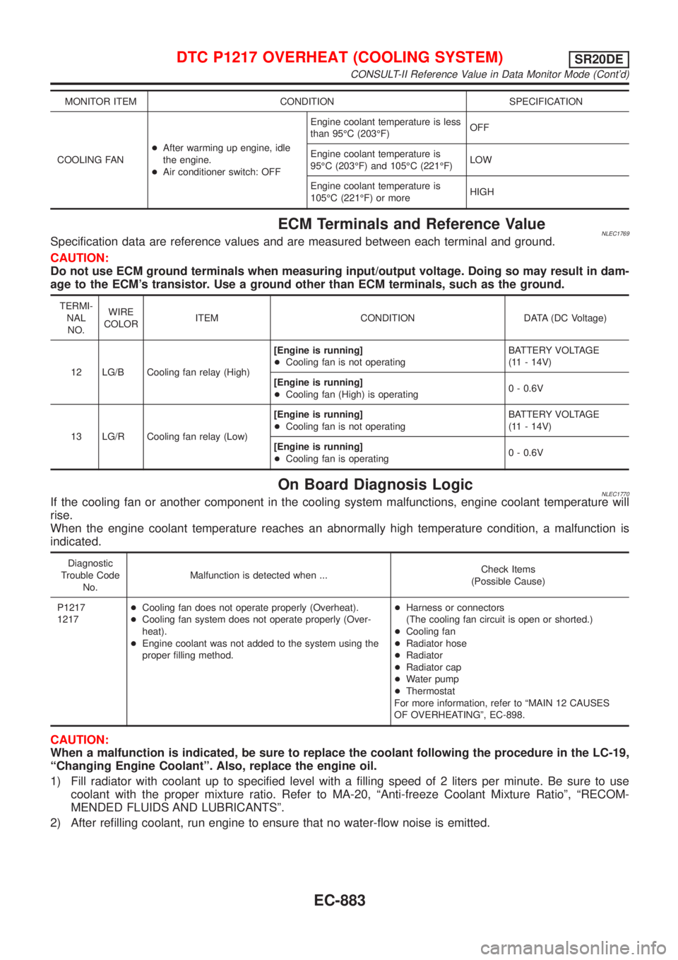
MONITOR ITEM CONDITION SPECIFICATION
COOLING FAN+After warming up engine, idle
the engine.
+Air conditioner switch: OFFEngine coolant temperature is less
than 95ÉC (203ÉF)OFF
Engine coolant temperature is
95ÉC (203ÉF) and 105ÉC (221ÉF)LOW
Engine coolant temperature is
105ÉC (221ÉF) or moreHIGH
ECM Terminals and Reference ValueNLEC1769Specification data are reference values and are measured between each terminal and ground.
CAUTION:
Do not use ECM ground terminals when measuring input/output voltage. Doing so may result in dam-
age to the ECM's transistor. Use a ground other than ECM terminals, such as the ground.
TERMI-
NAL
NO.WIRE
COLORITEM CONDITION DATA (DC Voltage)
12 LG/B Cooling fan relay (High)[Engine is running]
+Cooling fan is not operatingBATTERY VOLTAGE
(11 - 14V)
[Engine is running]
+Cooling fan (High) is operating0 - 0.6V
13 LG/R Cooling fan relay (Low)[Engine is running]
+Cooling fan is not operatingBATTERY VOLTAGE
(11 - 14V)
[Engine is running]
+Cooling fan is operating0 - 0.6V
On Board Diagnosis LogicNLEC1770If the cooling fan or another component in the cooling system malfunctions, engine coolant temperature will
rise.
When the engine coolant temperature reaches an abnormally high temperature condition, a malfunction is
indicated.
Diagnostic
Trouble Code
No.Malfunction is detected when ...Check Items
(Possible Cause)
P1217
1217+Cooling fan does not operate properly (Overheat).
+Cooling fan system does not operate properly (Over-
heat).
+Engine coolant was not added to the system using the
proper filling method.+Harness or connectors
(The cooling fan circuit is open or shorted.)
+Cooling fan
+Radiator hose
+Radiator
+Radiator cap
+Water pump
+Thermostat
For more information, refer to ªMAIN 12 CAUSES
OF OVERHEATINGº, EC-898.
CAUTION:
When a malfunction is indicated, be sure to replace the coolant following the procedure in the LC-19,
ªChanging Engine Coolantº. Also, replace the engine oil.
1) Fill radiator with coolant up to specified level with a filling speed of 2 liters per minute. Be sure to use
coolant with the proper mixture ratio. Refer to MA-20, ªAnti-freeze Coolant Mixture Ratioº, ªRECOM-
MENDED FLUIDS AND LUBRICANTSº.
2) After refilling coolant, run engine to ensure that no water-flow noise is emitted.
DTC P1217 OVERHEAT (COOLING SYSTEM)SR20DE
CONSULT-II Reference Value in Data Monitor Mode (Cont'd)
EC-883