display NISSAN ALMERA TINO 2001 Service User Guide
[x] Cancel search | Manufacturer: NISSAN, Model Year: 2001, Model line: ALMERA TINO, Model: NISSAN ALMERA TINO 2001Pages: 3051, PDF Size: 46.38 MB
Page 32 of 3051

CONSULT-IINLAT0245After performing ªSELF-DIAGNOSTIC PROCEDURE (WITH CON-
SULT-II)º (AT-31), place check marks for results on the ªDIAGNOS-
TIC WORKSHEETº, AT-42. Reference pages are provided follow-
ing the items.
NOTICE:
+Additional CONSULT-II information can be found in the Opera-
tion Manual supplied with the CONSULT-II unit.
SAT250K
SELF-DIAGNOSTIC PROCEDURE (WITH CONSULT-II)NLAT0245S011. Turn on CONSULT-II and touch ªCVTº for TCM self-diagnosis.
If CVT is not displayed, check TCM power supply and ground
circuit. Refer to AT-58. If result is NG, refer to EL section
(ªPOWER SUPPLY ROUTINGº).
SAT987J
2. Touch ªSELF-DIAG RESULTSº.
Display shows malfunction experienced since the last erasing
operation.
CONSULT-II performs REAL-TIME SELF-DIAGNOSIS.
Also, any malfunction detected while in this mode will be dis-
played at real time.
SELF-DIAGNOSTIC RESULT TEST MODENLAT0245S02
Detected items
(Screen terms for CONSULT-II, ªSELF-DIAG
RESULTSº test mode)Malfunction is detected when ... Remarks
Item Display
No failure
(NO SELF DIAGNOSTIC FAILURE INDICATED
FURTHER TESTING MAY BE REQUIRED**)+No failure has been detected.
Initial start+This is not a malfunction message (Whenever shut-
ting off a power supply to the TCM, this message
appears on the screen.) INITIAL START
Ð
Output pulley speed
signalO/P PULLY SPD SIG+TCM does not receive the proper voltage signal from
the sensor.
Primary speed sensor I/P PULLY SPD SIG+TCM does not receive the proper voltage signal from
the sensor.
Throttle position sen-
sorTHROTTLE POSI
SEN+TCM receives an excessively low or high voltage
from the sensor.
Stepping motor circuit STEP MOTOR+Not proper voltage change of the TCM terminal when
operating step motor.
ON BOARD DIAGNOSTIC SYSTEM
DESCRIPTION
EXCEPT FOR EURO-OBD
CONSULT-II
AT-31
Page 33 of 3051

Detected items
(Screen terms for CONSULT-II, ªSELF-DIAG
RESULTSº test mode)Malfunction is detected when ... Remarks
Item Display
Stepping motor func-
tionÐ+Step motor is not operating according to the TCM.
Line pressure sensor LINE PRESSURE
SEN+TCM receives an excessively low or high voltage
from the sensor.
T/C clutch solenoid
valveT/C CLUTCH SOL/V+TCM detects an improper voltage drop when it tries
to operate the solenoid valve.
CVT fluid temperature
sensorFLUID TEMP SEN+TCM receives an excessively low or high voltage
from the sensor.
CVT SAFE FUNC-
TIONCVT SAFE FUNC-
TION+TCM is malfunctioning.
Engine speed signal ENGINE SPEED SIG+TCM does not receive the proper voltage signal from
the ECM.
Line pressure solenoid
valveLINE PRESSURE S/V+TCM detects an improper voltage drop when it tries
to operate the solenoid valve.
TCM (RAM) CONTROL UNIT
(RAM)+TCM memory (RAM) is malfunctioning.
TCM (ROM) CONTROL UNIT
(ROM)+TCM memory (ROM) is malfunctioning.
TCM (EEP ROM) CONT UNIT (EEP
ROM)+TCM memory (EEP ROM) is malfunctioning.
DATA MONITOR MODE (CVT)NLAT0245S03
Item DisplayMonitor item
Description Remarks
TCM input
signalsMain sig-
nals
Vehicle speed sensor
(Secondary speed sensor)VHCL SPEED
SE
[km/h] or [mph] X Ð+Vehicle speed com-
puted from signal of
revolution sensor is dis-
played.When racing engine in ªNº
or ªPº position with vehicle
stationary, CONSULT-II data
may not indicate 0 km/h (0
mph).
Throttle position sensor THRTL POS
SEN
[V]XÐ+Throttle position sensor
signal voltage is dis-
played.Ð
CVT fluid temperature
sensorFLUID TEMP
SE
[V]
XÐ+CVT fluid temperature
sensor signal voltage is
displayed.
+Signal voltage lowers
as fluid temperature
rises.Ð
Battery voltage BATTERY VOLT
[V]XÐ+Source voltage of TCM
is displayed.Ð
Engine speed ENGINE
SPEED
[rpm] X X+Engine speed, com-
puted from engine
speed signal, is dis-
played.Engine speed display may
not be accurate under
approx. 800 rpm. It may not
indicate 0 rpm even when
engine is not running.
ON BOARD DIAGNOSTIC SYSTEM
DESCRIPTION
EXCEPT FOR EURO-OBD
CONSULT-II (Cont'd)
AT-32
Page 34 of 3051

Item DisplayMonitor item
Description Remarks
TCM input
signalsMain sig-
nals
P/N position switch N POSITION
SW
[ON/OFF]XÐ+ON/OFF state com-
puted from signal of
P/N position SW is dis-
played.Ð
R position switch R POSITION
SW
[ON/OFF]XÐ+ON/OFF state com-
puted from signal of R
position SW is dis-
played.Ð
D position switch D POSITION
SW
[ON/OFF]XÐ+ON/OFF state com-
puted from signal of D
position SW is dis-
played.Ð
Sport mode switch S POSITION
SW
[ON/OFF]XÐ+ON/OFF status, com-
puted from signal of
Sport mode SW, is dis-
played.Ð
L position switch L POSITION
SW
[ON/OFF]XÐ+ON/OFF status, com-
puted from signal of L
position SW, is dis-
played.Ð
Closed throttle position
switchCLOSED
THL/SW
[ON/OFF]XÐ+ON/OFF status, com-
puted from signal of
closed throttle position
SW, is displayed.Ð
Wide open throttle position
switchW/O THRL/
P-SW
[ON/OFF]XÐ+ON/OFF status, com-
puted from signal of
wide open throttle posi-
tion SW, is displayed.Ð
Selector lever position SLCT LVR POSI
ÐX+Selector lever position
data, used for computa-
tion by TCM, is dis-
played.+A specific value used for
control is displayed if fail-
safe is activated due to
error.
Vehicle speed VEHICLE
SPEED
[km/h] or [mph]ÐX+Vehicle speed data,
used for computation
by TCM, is displayed.Ð
Throttle position THROTTLE
POSI
[/8]ÐX+Throttle position data,
used for computation
by TCM, is displayed.+A specific value used for
control is displayed if fail-
safe is activated due to
error.
Line pressure duty LINE PRES
DTY
[%] Ð X+Control value of line
pressure solenoid
valve, computed by
TCM from each input
signal, is displayed.Ð
Torque converter clutch
solenoid valve dutyTCC S/V DUTY
[%]
ÐX+Control value of torque
converter clutch sole-
noid valve, computed
by TCM from each
input signal, is dis-
played.Ð
Self-diagnosis display
lamp
(SPORT indicator lamp)PAT MONI
LAMP
[ON/OFF]ÐX+Control status of
SPORT indicator lamp
is displayed.Ð
ON BOARD DIAGNOSTIC SYSTEM
DESCRIPTION
EXCEPT FOR EURO-OBD
CONSULT-II (Cont'd)
AT-33
Page 35 of 3051

Item DisplayMonitor item
Description Remarks
TCM input
signalsMain sig-
nals
Line pressure sensor LINE PRES
SEN [V] X Ð+CVT fluid pressure sen-
sor signal voltage is
displayed.Ð
Primary pulley speed sen-
sorI/P PULLY SPD
[rpm]
XX+Primary pulley speed
computed from signal
of primary pulley speed
sensor is displayed.
Secondary pulley speed
sensorO/P PULLY SPD
[rpm]
ÐÐ+Secondary pulley speed
computed from signal
of secondary speed
sensor is displayed.Ð
Stop lamp switch BRAKE SW
[ON/OFF] X Ð+ON/OFF position signal
of stop lamp switch is
displayed.Ð
ABS signal ABS SIGNAL
[ON/OFF]
XÐ+ABS operation signal
(ON/OFF) from ABS
control unit is dis-
played.Ð
CVT ratio CVT RATIO [Ð]
ÐX+Real CVT ratio oper-
ated TCM is displayed.Ð
Step PLY CONT
STEP [step]ÐX+Step motor position is
displayed.Ð
X: Applicable
Ð: Not applicable
SAT250K
HOW TO ERASE SELF-DIAGNOSTIC RESULTS
(
WITH CONSULT-II)NLAT0245S091. If the ignition switch stays ªONº after repair work, be sure to
turn ignition switch ªOFFº once. Wait for at least 3 seconds and
then turn it ªONº again.
2. Turn CONSULT-II ªONº, and touch ªCVTº.
SAT252K
3. Touch ªSELF-DIAG RESULTSº.
ON BOARD DIAGNOSTIC SYSTEM
DESCRIPTION
EXCEPT FOR EURO-OBD
CONSULT-II (Cont'd)
AT-34
Page 40 of 3051
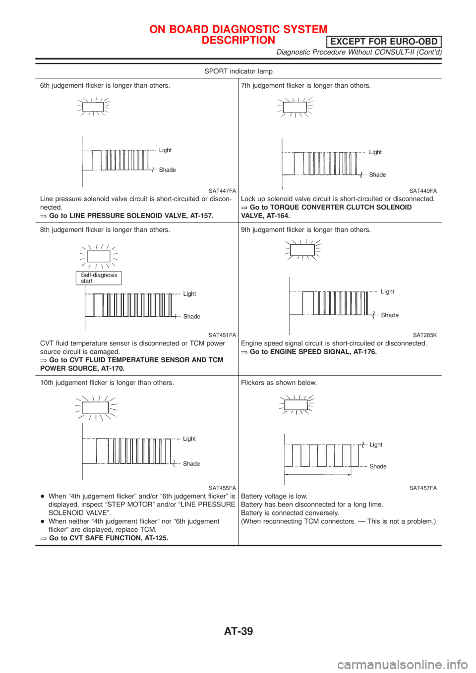
SPORT indicator lamp
6th judgement flicker is longer than others.
SAT447FA
Line pressure solenoid valve circuit is short-circuited or discon-
nected.
ÞGo to LINE PRESSURE SOLENOID VALVE, AT-157.7th judgement flicker is longer than others.
SAT449FA
Lock up solenoid valve circuit is short-circuited or disconnected.
ÞGo to TORQUE CONVERTER CLUTCH SOLENOID
VALVE, AT-164.
8th judgement flicker is longer than others.
SAT451FA
CVT fluid temperature sensor is disconnected or TCM power
source circuit is damaged.
ÞGo to CVT FLUID TEMPERATURE SENSOR AND TCM
POWER SOURCE, AT-170.9th judgement flicker is longer than others.
SAT285K
Engine speed signal circuit is short-circuited or disconnected.
ÞGo to ENGINE SPEED SIGNAL, AT-176.
10th judgement flicker is longer than others.
SAT455FA
+When ª4th judgement flickerº and/or ª6th judgement flickerº is
displayed, inspect ªSTEP MOTORº and/or ªLINE PRESSURE
SOLENOID VALVEº.
+When neither ª4th judgement flickerº nor ª6th judgement
flickerº are displayed, replace TCM.
ÞGo to CVT SAFE FUNCTION, AT-125.Flickers as shown below.
SAT457FA
Battery voltage is low.
Battery has been disconnected for a long time.
Battery is connected conversely.
(When reconnecting TCM connectors. Ð This is not a problem.)
ON BOARD DIAGNOSTIC SYSTEM
DESCRIPTION
EXCEPT FOR EURO-OBD
Diagnostic Procedure Without CONSULT-II (Cont'd)
AT-39
Page 56 of 3051
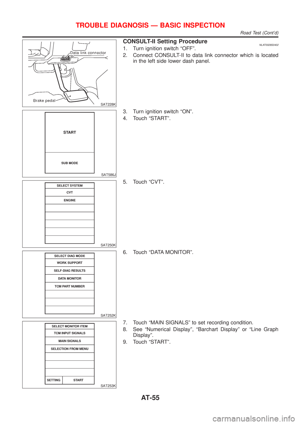
SAT228K
CONSULT-II Setting ProcedureNLAT0028S04021. Turn ignition switch ªOFFº.
2. Connect CONSULT-II to data link connector which is located
in the left side lower dash panel.
SAT586J
3. Turn ignition switch ªONº.
4. Touch ªSTARTº.
SAT250K
5. Touch ªCVTº.
SAT252K
6. Touch ªDATA MONITORº.
SAT253K
7. Touch ªMAIN SIGNALSº to set recording condition.
8. See ªNumerical Displayº, ªBarchart Displayº or ªLine Graph
Displayº.
9. Touch ªSTARTº.
TROUBLE DIAGNOSIS Ð BASIC INSPECTION
Road Test (Cont'd)
AT-55
Page 57 of 3051

SAT236K
10. When performing cruise test, touch ªStore Dataº.
SAT237K
11. After finishing cruise test part 1, touch ªSTOPº.
SAT254K
12. Touch ªSTOREº.
SAT608J
13. Touch ªDISPLAYº.
SAT238K
14. Touch ªPRINTº.
15. Check the monitor data printed out.
16. Continue cruise test part 2 and 3.
TROUBLE DIAGNOSIS Ð BASIC INSPECTION
Road Test (Cont'd)
AT-56
Page 126 of 3051

DescriptionNLAT0249ªCVT SAFE FUNCTIONº is function to protect CVT.
ON BOARD DIAGNOSIS LOGICNLAT0249S01
Diagnostic trouble code Malfunction is detected when ... Check items (Possible cause)
: CVT SAFE FUNCTION
TCM is malfunctioning TCM
: 10th judgement flicker
SAT250K
SAT252K
SAT270K
DIAGNOSTIC TROUBLE CODE (DTC) CONFIRMATION
PROCEDURE
NLAT0249S02With CONSULT-II
1) Turn ignition switch ªONº and select ªDATA MONITORº mode
for CVT with CONSULT-II.
2) Start engine.
3) Run engine for at least 2 seconds at idle speed.
Without CONSULT-II
1) Start engine.
2) Perform self-diagnosis. Refer to TCM Self-diagnostic Proce-
dure (No Tools), AT-28 Ð EURO-OBD/AT-35, Except for
EURO-OBD.
Diagnostic ProcedureNLAT0250
1 CHECK INPUT SIGNAL (With CONSULT-II)
1. Turn ignition switch to ªONº and select ªSELF-DIAG RESULTSº mode for CVT with CONSULT-II.
2. Touch ªERASEº.
Perform ªDIAGNOSTIC TROUBLE CODE (DTC) CONFIRMATION PROCEDUREº above.
Is the ªCVT SAFE FUNCTIONº displayed again?
OK©Replace TCM.
NG©INSPECTION END
CVT SAFE FUNCTION
Description
AT-125
Page 182 of 3051

Diagnostic Procedure=NLAT0289
1 CHECK DTC
With CONSULT-II
1. Turn ignition switch ªONº and select ªSELF-DIAG RESULTSº mode for CVT with CONSULT-II.
2. Touch ªERASEº.
PERFORM DIAGNOSTIC TROUBLE CODE (DTC) CONFIRMATION PROCEDURE.
See previous page.
Is the ªCONTROL UNIT (RAM) or CONTROL UNIT (ROM)º displayed again?
Ye s©Replace TCM.
No©INSPECTION END
CONTROL UNIT (RAM), CONTROL UNIT (ROM)
Diagnostic Procedure
AT-181
Page 184 of 3051

Diagnostic Procedure=NLAT0242
1 CHECK DTC
With CONSULT-II
1. Turn ignition switch ªONº and select ªSELF-DIAG RESULTSº mode for CVT with CONSULT-II.
2. Move selector lever to ªRº position.
3. Depress accelerator pedal (Full throttle position).
4. Touch ªERASEº.
5. Turn ignition switch ªOFFº position for 10 seconds.
PERFORM DIAGNOSTIC TROUBLE CODE (DTC) CONFIRMATION PROCEDURE.
See previous page.
Is the ªCONT UNIT (EEPROM)º displayed again?
Ye s©Replace TCM.
No©INSPECTION END
CONTROL UNIT (EEPROM)
Diagnostic Procedure
AT-183