wheel bolts NISSAN ALMERA TINO 2001 Service User Guide
[x] Cancel search | Manufacturer: NISSAN, Model Year: 2001, Model line: ALMERA TINO, Model: NISSAN ALMERA TINO 2001Pages: 3051, PDF Size: 46.38 MB
Page 2307 of 3051
WARNING:
+Position vehicle on a flat and solid surface.
+Place chocks at front and back of rear wheels.
+Do not remove engine until exhaust system has com-
pletely cooled off, otherwise, you may burn yourself
and/or fire may break out in fuel line.
+Before disconnecting fuel hose, release pressure.
Refer to EC-43, ªFuel Pressure Releaseº.
+Be sure to lift engine and transaxle in a safe manner.
+For engines not equipped with engine slingers, attach
proper slingers and bolts described in PARTS CATALOG.
CAUTION:
+When lifting engine, be sure to clear surrounding parts.
Use special care near accelerator wire casing, brake lines
and brake master cylinder.
+When lifting the engine, always use engine slingers in a
safe manner.
+When removing drive shaft, be careful not to damage
grease seal of transaxle.
+Before separating engine and transaxle, remove crank-
shaft position sensor (POS) from the cylinder block
assembly.
+Always be extra careful not to damage edge of crankshaft
position sensor (POS), or signal plate teeth.
Engine cannot be removed separately from transaxle. Remove
engine with transaxle as an assembly.
REMOVALNLEM0022S011. Drain coolant from radiator and cylinder block. Refer to LC-18,
ªChanging Engine Coolantº.
2. Remove coolant reservoir tank and bracket.
3. Drain engine oil.
4. Remove battery and battery tray.
5. Remove air cleaner and air duct.
6. Remove drive belts.
7. Remove alternator and air conditioner compressor from
engine.
8. Remove power steering oil pump from engine and position
aside.
Power steering oil pump does not need to be disconnected
from power steering tubes.
ENGINE ASSEMBLYQG
Removal and Installation (Cont'd)
EM-50
Page 2310 of 3051
Removal and InstallationNLEM0024CAUTION:
+When installing sliding parts such as bearings and
pistons, apply engine oil on the sliding surfaces.
+Place removed parts, such as bearings and bearing caps,
in their proper order and direction.
+When installing connecting rod nuts and main bearing cap
bolts, apply new engine oil to threads and seating sur-
faces.
+Do not allow any magnetic materials to contact the signal
plate teeth of flywheel or drive plate, and rear plate.
+Remove the crankshaft position sensor (POS).
+Be careful not to damage sensor edges and single plate
teeth.
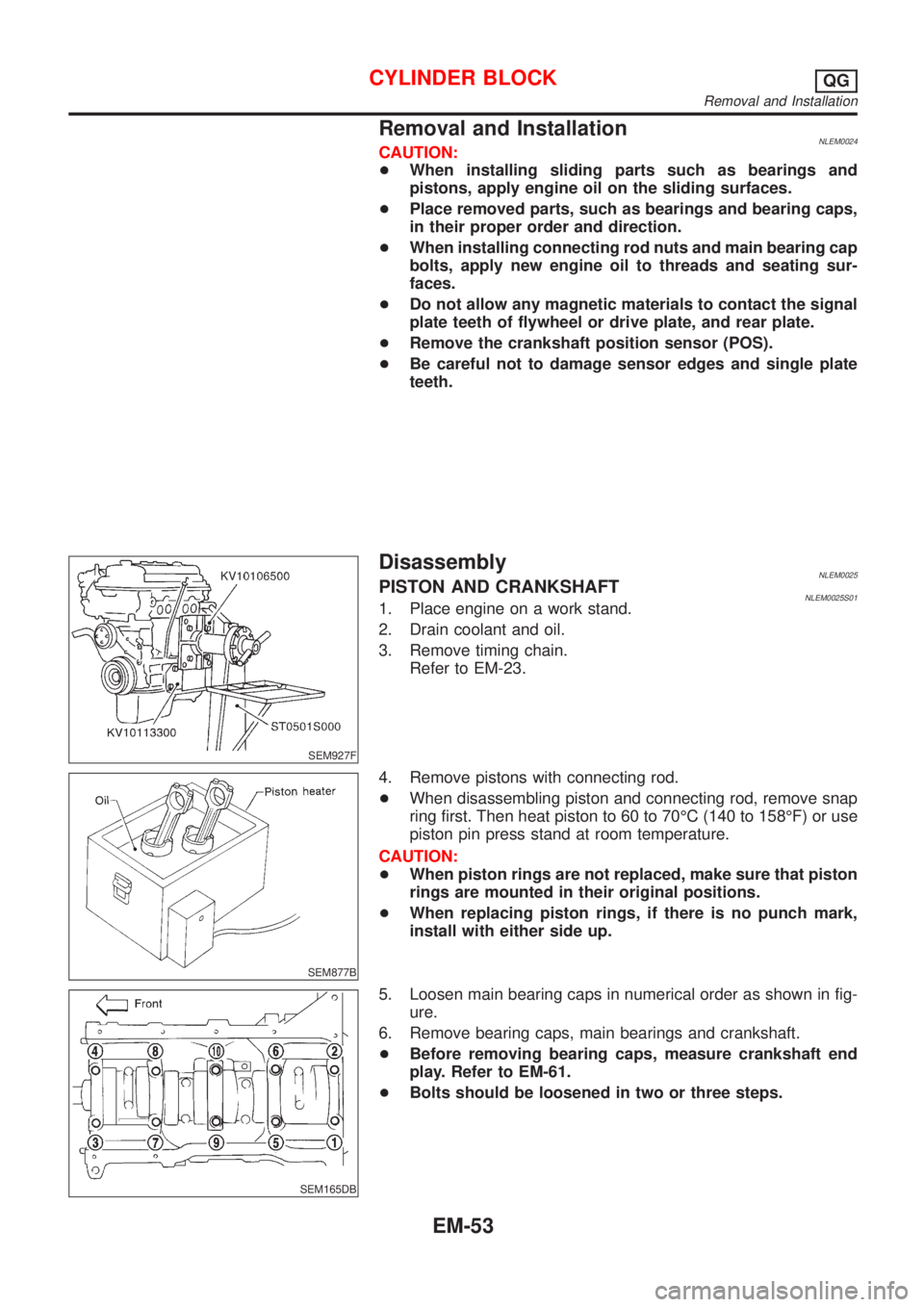
SEM927F
DisassemblyNLEM0025PISTON AND CRANKSHAFTNLEM0025S011. Place engine on a work stand.
2. Drain coolant and oil.
3. Remove timing chain.
Refer to EM-23.
SEM877B
4. Remove pistons with connecting rod.
+When disassembling piston and connecting rod, remove snap
ring first. Then heat piston to 60 to 70ÉC (140 to 158ÉF) or use
piston pin press stand at room temperature.
CAUTION:
+When piston rings are not replaced, make sure that piston
rings are mounted in their original positions.
+When replacing piston rings, if there is no punch mark,
install with either side up.
SEM165DB
5. Loosen main bearing caps in numerical order as shown in fig-
ure.
6. Remove bearing caps, main bearings and crankshaft.
+Before removing bearing caps, measure crankshaft end
play. Refer to EM-61.
+Bolts should be loosened in two or three steps.
CYLINDER BLOCKQG
Removal and Installation
EM-53
Page 2354 of 3051

CAUTION:
+After removing timing chain, do not turn crankshaft and
camshaft separately, or valves will strike piston heads.
+When installing chain tensioner, oil seals, or other sliding
parts, lubricate contacting surfaces with new engine oil.
+Apply new engine oil to bolt threads and seat surfaces
when installing camshaft sprocket and crankshaft pulley.
RemovalNLEM01261. Remove engine under cover.
2. Remove front RH wheel and engine side cover.
3. Drain coolant by removing cylinder block drain plug and lower
radiator hose. Refer to LC-38, ªChanging Engine Coolantº.
4. Remove drive belts and water pump pulley.
5. Disconnect the following parts:
+Vacuum hoses
+Wires
+Harness
+Connectors
SEM029G
6. Remove rocker cover bolts in numerical order.
7. Remove rocker cover.
SEM287G
8. Remove cylinder head outside bolts.
TIMING CHAINSR
Components (Cont'd)
EM-97
Page 2361 of 3051

BEM006
SEM051G
18. Remove old liquid gasket from mating surfaces of rocker cover
and cylinder head.
19. Apply a continuous bead of liquid gasket to rocker cover gas-
ket and cylinder head as shown in the illustrations.
+Use Genuine RTV silicone sealant Part No. 999MP-A7007
or equivalent.
SEM052G
20. Install rocker cover and oil separator.
+Be sure to install washers between bolts and rocker cover.
+Tightening procedure
STEP 1: Tighten bolts1-10-11-13-8inthat order.
STEP 2: Tighten bolts1-13inthat order.
:8-10N´m(0.8 - 1.0 kg-m, 69 - 87 in-lb)
21. Install the following parts:
+Spark plugs and leads
+Water pump pulley and drive belts.
For adjusting drive belt deflection, refer to EM-86, ªChecking
Drive Beltsº.
+Refit lower radiator hose and cylinder block drain plug.
+Refill with engine coolant. Refer to LC-38, ªChanging Engine
Coolantº.
+Front RH wheel
+Engine under cover
22. Connect the following:
+Vacuum hoses
+Wire harnesses and connectors
TIMING CHAINSR
Installation (Cont'd)
EM-104
Page 2366 of 3051

RemovalNLEM01311. Release fuel pressure.
Refer to EC-578, ªFuel Pressure Releaseº.
2. Remove engine under covers.
3. Remove front RH wheel and engine side cover.
4. Drain coolant by removing cylinder block drain plug and radia-
tor drain cock. Refer to LC-38, ªChanging Engine Coolantº.
5. Remove radiator.
6. Remove air duct to intake manifold.
7. Disconnect the following parts:
+Vacuum hoses
+Fuel hoses
+Wires
+Harness
+Connectors
+Front exhaust tube
8. Remove all spark plugs.
SEM029G
9. Remove rocker cover bolts in numerical order.
10. Remove rocker cover.
SEM030G
11. Remove intake manifold supports.
SEM065G
12. Remove water pipe assembly.
CYLINDER HEADSR
Removal
EM-109
Page 2386 of 3051

SEM052G
17. Install rocker cover and oil separator.
+Be sure to install washers between bolts and rocker cover.
+Tightening procedure
STEP 1: Tighten bolts1-10-11-13-8inthat order.
STEP 2: Tighten bolts1-13inthat order.
:8-10N´m(0.8 - 1.0 kg-m, 69 - 87 in-lb)
18. Install the following parts:
+Spark plugs and leads
+Radiator
Refit hoses and refill with coolant.
Refer to LC-38, ªChanging Engine Coolantº.
+Front RH wheel
+Engine under covers
19. Connect the following:
+Vacuum hoses
+Fuel hoses
+Wire harnesses and connectors
+Air duct to intake manifold
+Front exhaust tube
CYLINDER HEADSR
Installation (Cont'd)
EM-129
Page 2387 of 3051

Removal and InstallationNLEM0137
NEM354
1. Stopper
2. Bracket
3. Front insulator assembly4. Center member
5. Pad
6. Right insulator assembly7. Bracket
8. Rear insulator assembly
9. Left insulator assembly
WARNING:
+Position vehicle on a flat and solid surface.
+Place chocks at front and back of rear wheels.
+Do not remove engine until exhaust system has com-
pletely cooled off, otherwise you may burn yourself and/or
fire may break out in fuel line.
+Before disconnecting fuel hose, release pressure. Refer to
EC-578, ªFuel Pressure Releaseº.
+Before removing front axle from transaxle, place safety
stands under designated front supporting points. Refer to
GI-43, ªGarage Jack and Safety Standº.
+Be sure to lift engine and transaxle in a safe manner.
+For engines not equipped with engine slingers, attach
proper slingers and bolts described in PARTS CATALOG.
CAUTION:
+When lifting engine, be sure to clear surrounding parts.
Use special care near accelerator wire casing, brake lines
and brake master cylinder.
+In lifting the engine, always use engine slingers in a safe
manner.
+In removing drive shaft, be careful not to damage grease
seal of transaxle.
+Before separating engine and transaxle, remove the
ENGINE ASSEMBLYSR
Removal and Installation
EM-130
Page 2475 of 3051

Removal and InstallationNLEM0069
SEM554G
WARNING:
+Situate vehicle on a flat and solid surface.
+Place chocks at front and back of rear wheels.
+Do not remove engine until exhaust system has com-
pletely cooled off. Otherwise, you may burn yourself
and/or fire may break out in fuel line.
+For safety during subsequent steps, the tension of wires
should be slackened against the engine.
+Before removing front axle from transaxle, place safety
stands under designated front supporting points. Refer to
GI-43, ªGarage Jack and Safety Standº.
+Be sure to hoist engine and transaxle in a safe manner.
+For engines not equipped with engine slingers, attach
proper slingers and bolts described in PARTS CATALOG.
CAUTION:
+When lifting engine, be careful not to strike adjacent parts,
especially the following: Accelerator wire casing, brake
lines, and brake master cylinder.
+In hoisting the engine, always use engine slingers in a
safe manner.
+In removing drive shaft, be careful not to damage grease
seal of transaxle.
+Before separating engine and transaxle, remove the
ENGINE ASSEMBLYYD
Removal and Installation
EM-218
Page 2476 of 3051
crankshaft position sensor (TDC sensor) from the assem-
bly.
+Always pay extra attention not to damage edge of crank-
shaft position sensor (TDC sensor) or ring gear teeth.
REMOVALNLEM0069S011. Remove engine undercover, and hood for hoisting.
2. Drain coolant from both cylinder block and radiator. Refer to
LC-59, ªChanging Engine Coolantº.
3. Remove the following parts:
+Battery
+RH and LH front wheels
+RH and LH splash covers (combined with undercover)
+Auxiliary belts
+Alternator
+Alternator brackets
+Radiator and cooling fan
+Engine cover
+Air ducts and air cleaner case
LH side of engine room:
4. Disconnect all harnesses and grounds that are connected to
components on vehicle.
5. Disconnect vacuum hose on vacuum pump side.
6. Disconnect fuel feed and fuel return hoses on engine side.
+Immediately put blind plugs into the openings to prevent
fuel from flowing out.
7. Disconnect heater hose. Plug opening of hose to prevent cool-
ant from flowing out.
RH side of engine room:
8. Remove air conditioner compressor from brackets and move
it toward vehicle side. Secure compressor on vehicle side with
rope.
Vehicle underside:
9. Remove exhaust front tube.
10. Disconnect two hoses from power steering pump and plug to
stop fluid.
11. Remove M/T control rod and support rod.
12. Remove ABS wheel sensor, and temporarily hang brake cali-
per with rope on vehicle side.
13. Remove RH and LH drive shafts.
SEM499G
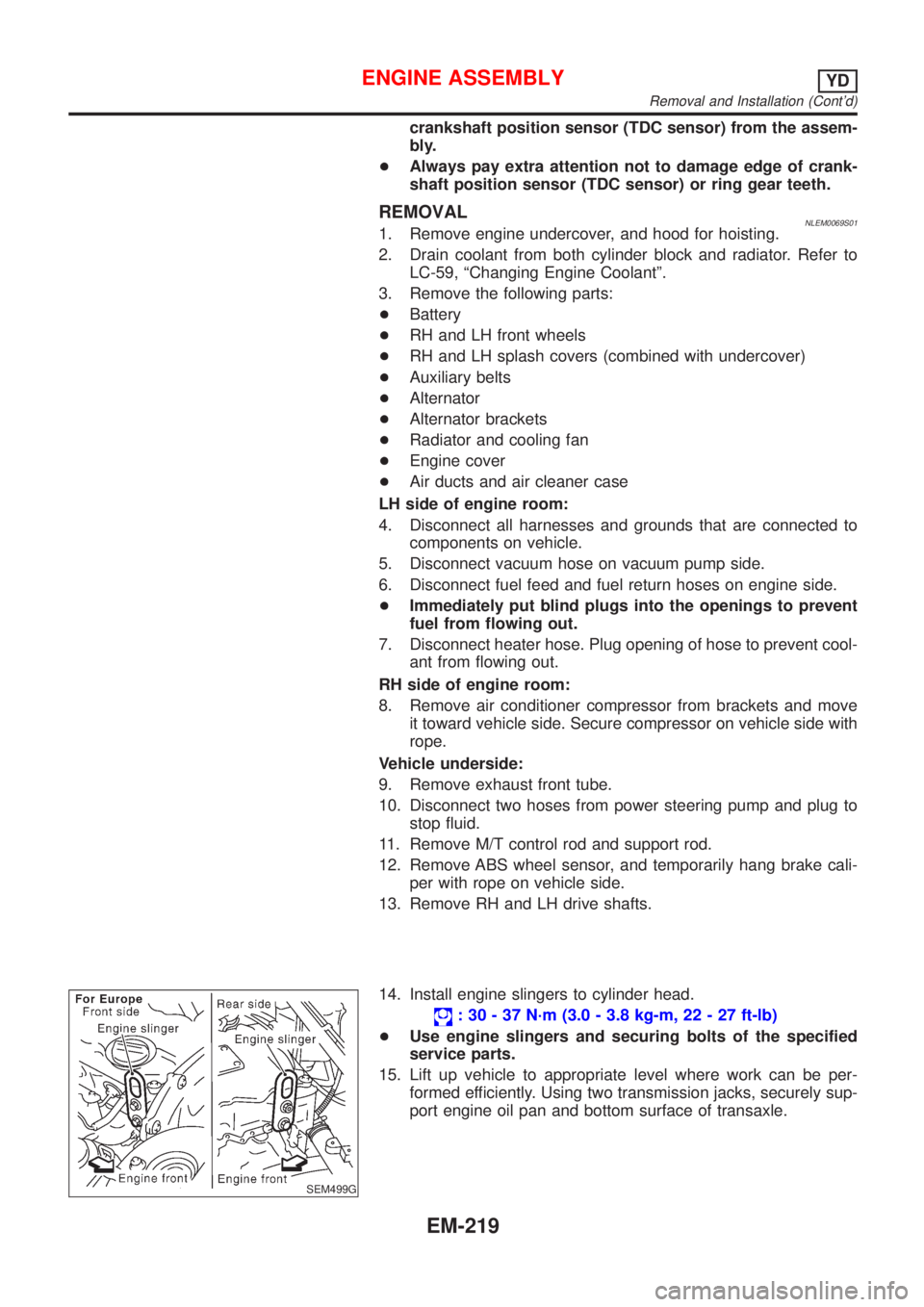
14. Install engine slingers to cylinder head.
: 30 - 37 N´m (3.0 - 3.8 kg-m, 22 - 27 ft-lb)
+Use engine slingers and securing bolts of the specified
service parts.
15. Lift up vehicle to appropriate level where work can be per-
formed efficiently. Using two transmission jacks, securely sup-
port engine oil pan and bottom surface of transaxle.
ENGINE ASSEMBLYYD
Removal and Installation (Cont'd)
EM-219
Page 2479 of 3051

Removal and InstallationNLEM0071CAUTION:
+When installing bearings, pistons, or other sliding parts,
lubricate contacting surfaces with new engine oil.
+Place removed parts such as bearings and bearing caps
in their proper order and direction.
+When installing connecting rod nuts, and main bearing
cap bolts, apply new engine oil to threads and seating
surfaces.
+Do not allow any magnetic materials to contact the signal
plate of flywheel.
+Do not remove the signal plate at back.
+Do not place the signal plate side facing under.
+Handle with care so as not to damage the signal plate
[especially four places on protrusions for signal of crank
position sensor (TDC sensor)].
DisassemblyNLEM0072PISTON AND CRANKSHAFTNLEM0072S011. Remove engine. Refer to ªENGINE ASSEMBLYº, ªRemoval
and Installationº, EM-218.
2. Place engine on a work stand.
a. Remove flywheel.
+Hold ring gear with ring gear stopper (KV10105630,
KV10105610). Then, loosen securing bolts with TORX socket
(size: Q8 E20, Commercial Service Tool) and remove them.
As an alternative method, hold the crankshaft pulley with a
pulley holder (SST) to remove the flywheel.
JEM192G
b. Install engine sub-attachment (SST) to rear surface of cylinder
block.
+To install, align the hole on the sub-attachment with the knock
pin on the cylinder block.
+The engine sub-attachment has five bolts.
c. Install engine attachment (SST).
+The four sets of bolts and nuts are multi-purpose products.
CYLINDER BLOCKYD
Removal and Installation
EM-222