NISSAN ALMERA TINO 2001 Service Repair Manual
Manufacturer: NISSAN, Model Year: 2001, Model line: ALMERA TINO, Model: NISSAN ALMERA TINO 2001Pages: 3051, PDF Size: 46.38 MB
Page 2261 of 3051
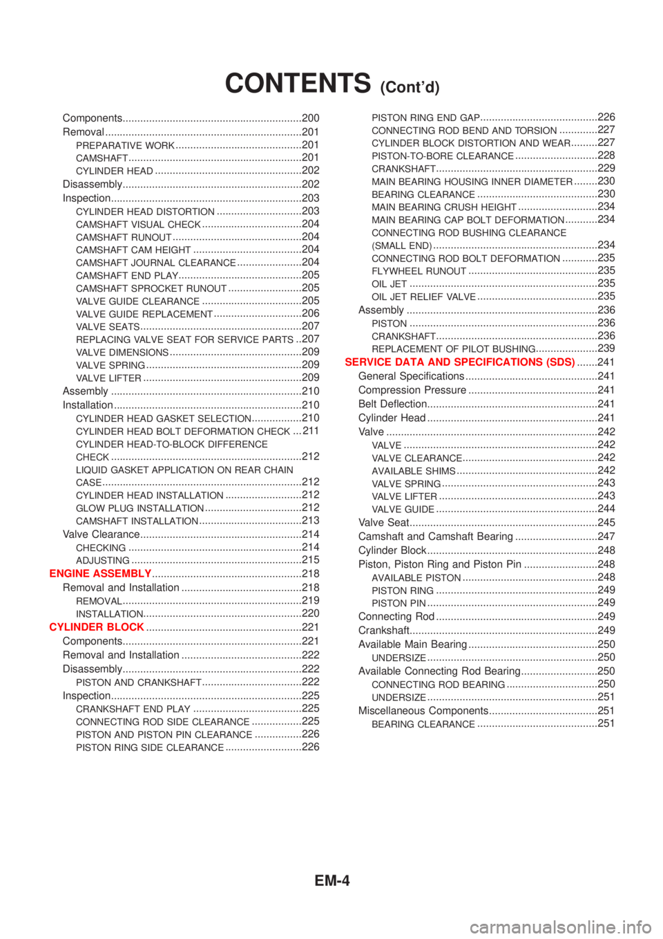
Components.............................................................200
Removal ...................................................................201
PREPARATIVE WORK...........................................201
CAMSHAFT...........................................................201
CYLINDER HEAD..................................................202
Disassembly.............................................................202
Inspection.................................................................203
CYLINDER HEAD DISTORTION.............................203
CAMSHAFT VISUAL CHECK..................................204
CAMSHAFT RUNOUT............................................204
CAMSHAFT CAM HEIGHT.....................................204
CAMSHAFT JOURNAL CLEARANCE......................204
CAMSHAFT END PLAY..........................................205
CAMSHAFT SPROCKET RUNOUT.........................205
VALVE GUIDE CLEARANCE..................................205
VALVE GUIDE REPLACEMENT..............................206
VALVE SEATS.......................................................207
REPLACING VALVE SEAT FOR SERVICE PARTS..207
VALVE DIMENSIONS.............................................209
VALVE SPRING.....................................................209
VALVE LIFTER......................................................209
Assembly .................................................................210
Installation ................................................................210
CYLINDER HEAD GASKET SELECTION.................210
CYLINDER HEAD BOLT DEFORMATION CHECK... 211
CYLINDER HEAD-TO-BLOCK DIFFERENCE
CHECK
.................................................................212
LIQUID GASKET APPLICATION ON REAR CHAIN
CASE
....................................................................212
CYLINDER HEAD INSTALLATION..........................212
GLOW PLUG INSTALLATION.................................212
CAMSHAFT INSTALLATION...................................213
Valve Clearance.......................................................214
CHECKING...........................................................214
ADJUSTING..........................................................215
ENGINE ASSEMBLY...................................................218
Removal and Installation .........................................218
REMOVAL.............................................................219
INSTALLATION......................................................220
CYLINDER BLOCK.....................................................221
Components.............................................................221
Removal and Installation .........................................222
Disassembly.............................................................222
PISTON AND CRANKSHAFT..................................222
Inspection.................................................................225
CRANKSHAFT END PLAY.....................................225
CONNECTING ROD SIDE CLEARANCE.................225
PISTON AND PISTON PIN CLEARANCE................226
PISTON RING SIDE CLEARANCE..........................226
PISTON RING END GAP........................................226
CONNECTING ROD BEND AND TORSION.............227
CYLINDER BLOCK DISTORTION AND WEAR.........227
PISTON-TO-BORE CLEARANCE............................228
CRANKSHAFT.......................................................229
MAIN BEARING HOUSING INNER DIAMETER........230
BEARING CLEARANCE.........................................230
MAIN BEARING CRUSH HEIGHT...........................234
MAIN BEARING CAP BOLT DEFORMATION...........234
CONNECTING ROD BUSHING CLEARANCE
(SMALL END)
........................................................234
CONNECTING ROD BOLT DEFORMATION............235
FLYWHEEL RUNOUT............................................235
OIL JET................................................................235
OIL JET RELIEF VALVE.........................................235
Assembly .................................................................236
PISTON................................................................236
CRANKSHAFT.......................................................236
REPLACEMENT OF PILOT BUSHING.....................239
SERVICE DATA AND SPECIFICATIONS (SDS).......241
General Specifications .............................................241
Compression Pressure ............................................241
Belt Deflection..........................................................241
Cylinder Head ..........................................................241
Valve ........................................................................242
VALVE..................................................................242
VALVE CLEARANCE..............................................242
AVAILABLE SHIMS................................................242
VALVE SPRING.....................................................243
VALVE LIFTER......................................................243
VALVE GUIDE.......................................................244
Valve Seat................................................................245
Camshaft and Camshaft Bearing ............................247
Cylinder Block ..........................................................248
Piston, Piston Ring and Piston Pin .........................248
AVAILABLE PISTON..............................................248
PISTON RING.......................................................249
PISTON PIN..........................................................249
Connecting Rod .......................................................249
Crankshaft................................................................249
Available Main Bearing ............................................250
UNDERSIZE..........................................................250
Available Connecting Rod Bearing..........................250
CONNECTING ROD BEARING...............................250
UNDERSIZE..........................................................251
Miscellaneous Components.....................................251
BEARING CLEARANCE.........................................251
CONTENTS(Cont'd)
EM-4
Page 2262 of 3051
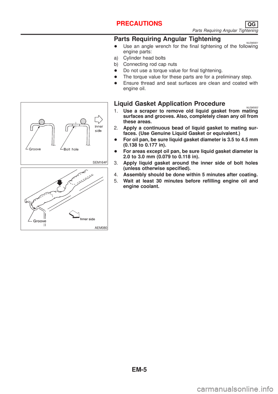
Parts Requiring Angular TighteningNLEM0001+Use an angle wrench for the final tightening of the following
engine parts:
a) Cylinder head bolts
b) Connecting rod cap nuts
+Do not use a torque value for final tightening.
+The torque value for these parts are for a preliminary step.
+Ensure thread and seat surfaces are clean and coated with
engine oil.
SEM164F
AEM080
Liquid Gasket Application ProcedureNLEM00021.Use a scraper to remove old liquid gasket from mating
surfaces and grooves. Also, completely clean any oil from
these areas.
2.Apply a continuous bead of liquid gasket to mating sur-
faces. (Use Genuine Liquid Gasket or equivalent.)
+For oil pan, be sure liquid gasket diameter is 3.5 to 4.5 mm
(0.138 to 0.177 in).
+For areas except oil pan, be sure liquid gasket diameter is
2.0 to 3.0 mm (0.079 to 0.118 in).
3.Apply liquid gasket around the inner side of bolt holes
(unless otherwise specified).
4.Assembly should be done within 5 minutes after coating.
5.Wait at least 30 minutes before refilling engine oil and
engine coolant.
PRECAUTIONSQG
Parts Requiring Angular Tightening
EM-5
Page 2263 of 3051
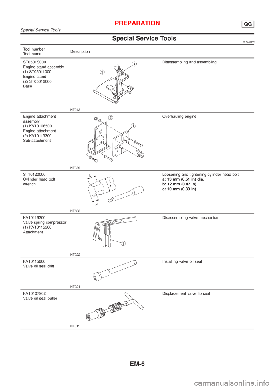
Special Service ToolsNLEM0003
Tool number
Tool nameDescription
ST0501S000
Engine stand assembly
(1) ST05011000
Engine stand
(2) ST05012000
Base
NT042
Disassembling and assembling
Engine attachment
assembly
(1) KV10106500
Engine attachment
(2) KV10113300
Sub-attachment
NT029
Overhauling engine
ST10120000
Cylinder head bolt
wrench
NT583
Loosening and tightening cylinder head bolt
a: 13 mm (0.51 in) dia.
b: 12 mm (0.47 in)
c: 10 mm (0.39 in)
KV10116200
Valve spring compressor
(1) KV10115900
Attachment
NT022
Disassembling valve mechanism
KV10115600
Valve oil seal drift
NT024
Installing valve oil seal
KV10107902
Valve oil seal puller
NT011
Displacement valve lip seal
PREPARATIONQG
Special Service Tools
EM-6
Page 2264 of 3051
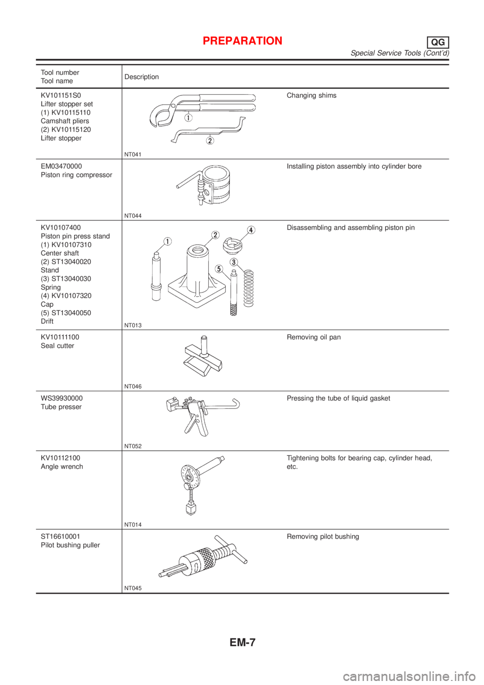
Tool number
Tool nameDescription
KV101151S0
Lifter stopper set
(1) KV10115110
Camshaft pliers
(2) KV10115120
Lifter stopper
NT041
Changing shims
EM03470000
Piston ring compressor
NT044
Installing piston assembly into cylinder bore
KV10107400
Piston pin press stand
(1) KV10107310
Center shaft
(2) ST13040020
Stand
(3) ST13040030
Spring
(4) KV10107320
Cap
(5) ST13040050
Drift
NT013
Disassembling and assembling piston pin
KV101111 0 0
Seal cutter
NT046
Removing oil pan
WS39930000
Tube presser
NT052
Pressing the tube of liquid gasket
KV10112100
Angle wrench
NT014
Tightening bolts for bearing cap, cylinder head,
etc.
ST16610001
Pilot bushing puller
NT045
Removing pilot bushing
PREPARATIONQG
Special Service Tools (Cont'd)
EM-7
Page 2265 of 3051
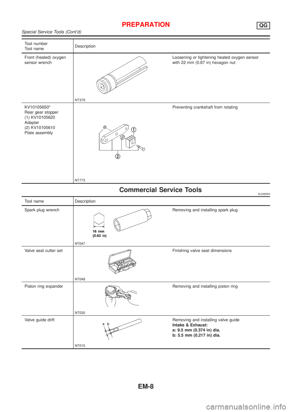
Tool number
Tool nameDescription
Front (heated) oxygen
sensor wrench
NT379
Loosening or tightening heated oxygen sensor
with 22 mm (0.87 in) hexagon nut
KV101056S0*
Rear gear stopper
(1) KV10105620
Adapter
(2) KV10105610
Plate assembly
NT773
Preventing crankshaft from rotating
Commercial Service ToolsNLEM0004
Tool name Description
Spark plug wrench
NT047
Removing and installing spark plug
Valve seat cutter set
NT048
Finishing valve seat dimensions
Piston ring expander
NT030
Removing and installing piston ring
Valve guide drift
NT015
Removing and installing valve guide
Intake & Exhaust:
a: 9.5 mm (0.374 in) dia.
b: 5.5 mm (0.217 in) dia.
PREPARATIONQG
Special Service Tools (Cont'd)
EM-8
Page 2266 of 3051
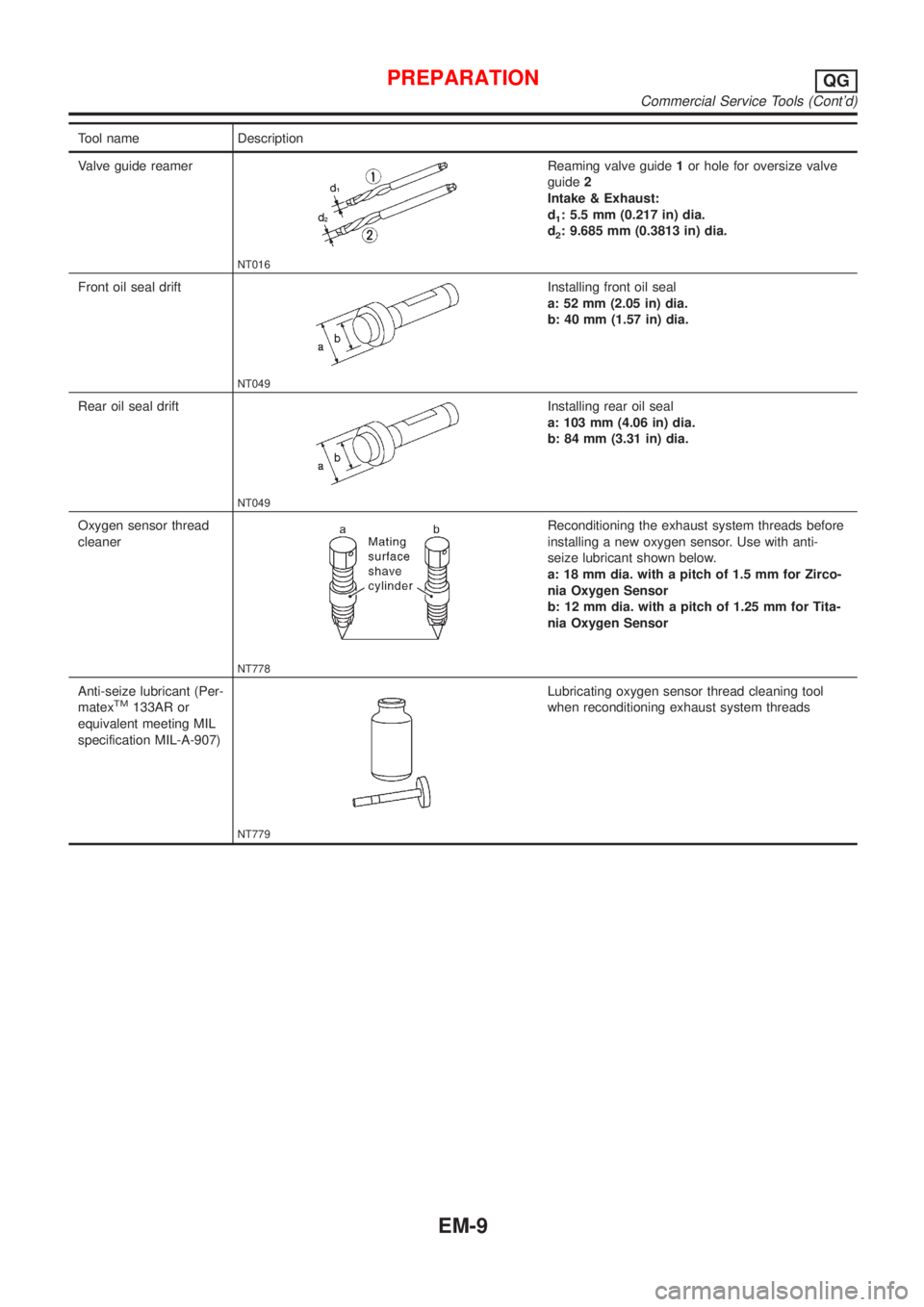
Tool name Description
Valve guide reamer
NT016
Reaming valve guide1or hole for oversize valve
guide2
Intake & Exhaust:
d
1: 5.5 mm (0.217 in) dia.
d
2: 9.685 mm (0.3813 in) dia.
Front oil seal drift
NT049
Installing front oil seal
a: 52 mm (2.05 in) dia.
b: 40 mm (1.57 in) dia.
Rear oil seal drift
NT049
Installing rear oil seal
a: 103 mm (4.06 in) dia.
b: 84 mm (3.31 in) dia.
Oxygen sensor thread
cleaner
NT778
Reconditioning the exhaust system threads before
installing a new oxygen sensor. Use with anti-
seize lubricant shown below.
a: 18 mm dia. with a pitch of 1.5 mm for Zirco-
nia Oxygen Sensor
b: 12 mm dia. with a pitch of 1.25 mm for Tita-
nia Oxygen Sensor
Anti-seize lubricant (Per-
matex
TM133AR or
equivalent meeting MIL
specification MIL-A-907)
NT779
Lubricating oxygen sensor thread cleaning tool
when reconditioning exhaust system threads
PREPARATIONQG
Commercial Service Tools (Cont'd)
EM-9
Page 2267 of 3051
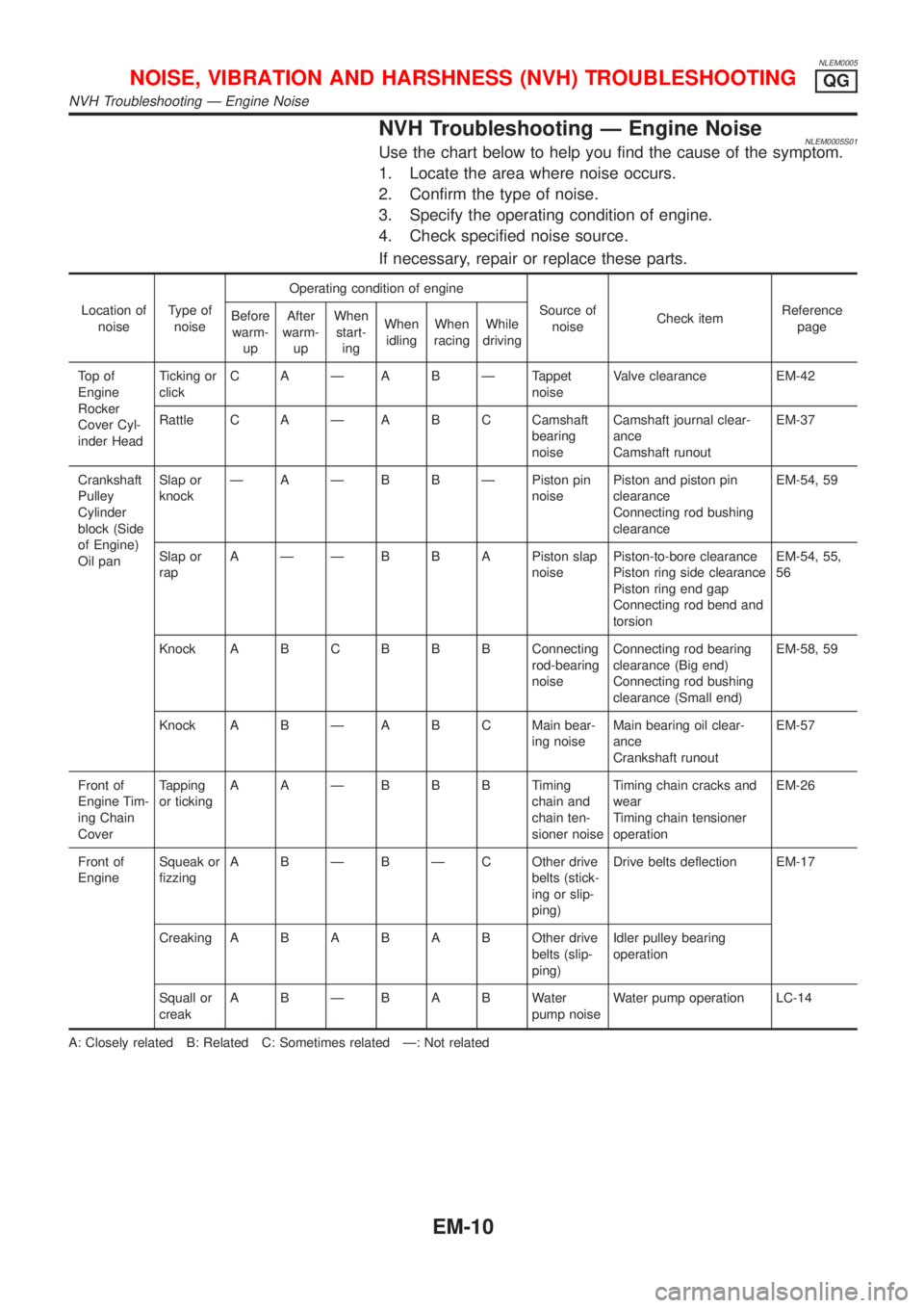
NLEM0005
NVH Troubleshooting Ð Engine NoiseNLEM0005S01Use the chart below to help you find the cause of the symptom.
1. Locate the area where noise occurs.
2. Confirm the type of noise.
3. Specify the operating condition of engine.
4. Check specified noise source.
If necessary, repair or replace these parts.
Location of
noiseType of
noiseOperating condition of engine
Source of
noiseCheck itemReference
page Before
warm-
upAfter
warm-
upWhen
start-
ingWhen
idlingWhen
racingWhile
driving
To p o f
Engine
Rocker
Cover Cyl-
inder HeadTicking or
clickC A Ð A B Ð Tappet
noiseValve clearance EM-42
Rattle C A Ð A B C Camshaft
bearing
noiseCamshaft journal clear-
ance
Camshaft runoutEM-37
Crankshaft
Pulley
Cylinder
block (Side
of Engine)
Oil panSlap or
knockÐ A Ð B B Ð Piston pin
noisePiston and piston pin
clearance
Connecting rod bushing
clearanceEM-54, 59
Slap or
rapA Ð Ð B B A Piston slap
noisePiston-to-bore clearance
Piston ring side clearance
Piston ring end gap
Connecting rod bend and
torsionEM-54, 55,
56
Knock A B CB B B Connecting
rod-bearing
noiseConnecting rod bearing
clearance (Big end)
Connecting rod bushing
clearance (Small end)EM-58, 59
Knock A B Ð A B C Main bear-
ing noiseMain bearing oil clear-
ance
Crankshaft runoutEM-57
Front of
Engine Tim-
ing Chain
CoverTapping
or tickingAAÐBBBTiming
chain and
chain ten-
sioner noiseTiming chain cracks and
wear
Timing chain tensioner
operationEM-26
Front of
EngineSqueak or
fizzingA B Ð B Ð C Other drive
belts (stick-
ing or slip-
ping)Drive belts deflection EM-17
CreakingABABABOther drive
belts (slip-
ping)Idler pulley bearing
operation
Squall or
creakABÐBABWater
pump noiseWater pump operation LC-14
A: Closely related B: Related C: Sometimes related Ð: Not related
NOISE, VIBRATION AND HARSHNESS (NVH) TROUBLESHOOTINGQG
NVH Troubleshooting Ð Engine Noise
EM-10
Page 2268 of 3051
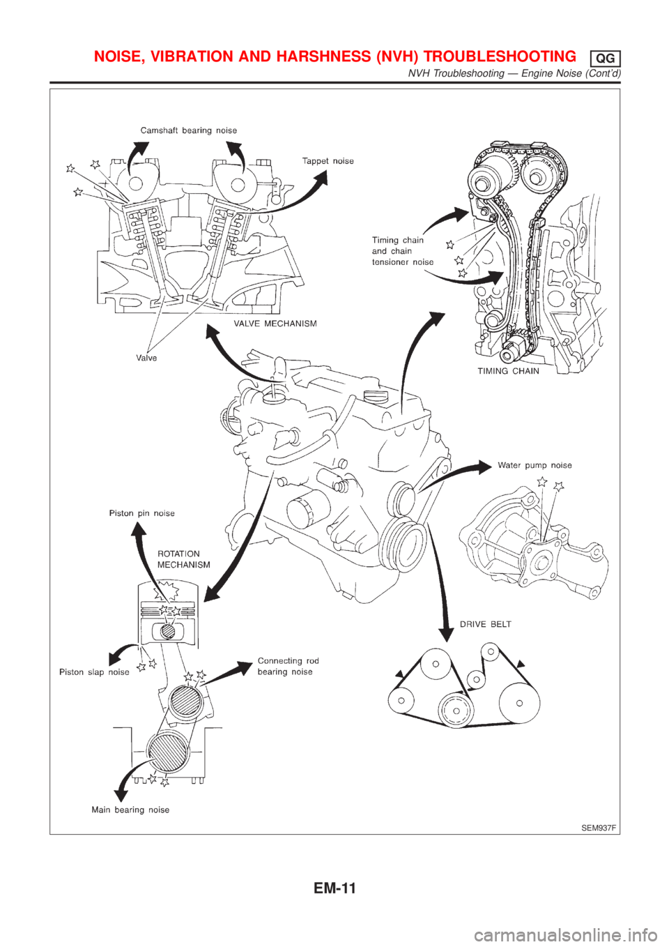
SEM937F
NOISE, VIBRATION AND HARSHNESS (NVH) TROUBLESHOOTINGQG
NVH Troubleshooting Ð Engine Noise (Cont'd)
EM-11
Page 2269 of 3051
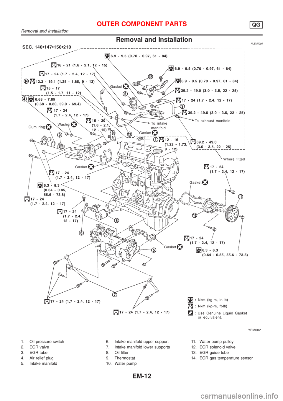
Removal and InstallationNLEM0006
YEM002
1. Oil pressure switch
2. EGR valve
3. EGR tube
4. Air relief plug
5. Intake manifold6. Intake manifold upper support
7. Intake manifold lower supports
8. Oil filter
9. Thermostat
10. Water pump11. Water pump pulley
12. EGR solenoid valve
13. EGR guide tube
14. EGR gas temperature sensor
OUTER COMPONENT PARTSQG
Removal and Installation
EM-12
Page 2270 of 3051
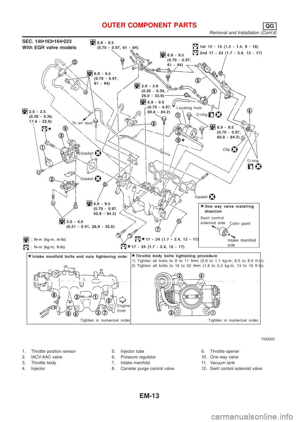
YEM003
1. Throttle position sensor
2. IACV-AAC valve
3. Throttle body
4. Injector5. Injector tube
6. Pressure regulator
7. Intake manifold
8. Canister purge control valve9. Throttle opener
10. One way valve
11. Vacuum tank
12. Swirl control solenoid valve
OUTER COMPONENT PARTSQG
Removal and Installation (Cont'd)
EM-13