cooling NISSAN ALMERA TINO 2001 Service Repair Manual
[x] Cancel search | Manufacturer: NISSAN, Model Year: 2001, Model line: ALMERA TINO, Model: NISSAN ALMERA TINO 2001Pages: 3051, PDF Size: 46.38 MB
Page 1 of 3051
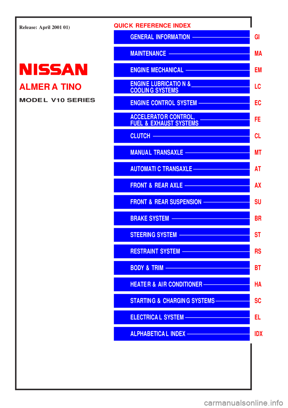
Release:April 2001 01)GENERALINFORMATIONGIMAINTENANCEMAENGINEMECHANICALEMENGINELUBRICATION&
COOLINGSYSTEMSLCENGINECONTROLSYSTEMECACCELERATORCONTROL,
FUEL&EXHAUSTSYSTEMSFECLUTCHCLMANUALTRANSAXLEMTAUTOMATICTRANSAXLEATFRONT&REARAXLEAXFRONT&REARSUSPENSIONSUBRAKESYSTEMBRSTEERINGSYSTEMSTRESTRAINTSYSTEMRSBODY&TRIMBTHEATER&AIRCONDITIONERHASTARTING&CHARGINGSYSTEMSSCELECTRICALSYSTEMELALPHABETICALINDEXIDXALMERATINOMODELV10SERIESQUICKREFERENCEINDEX
Page 8 of 3051
AAT470A
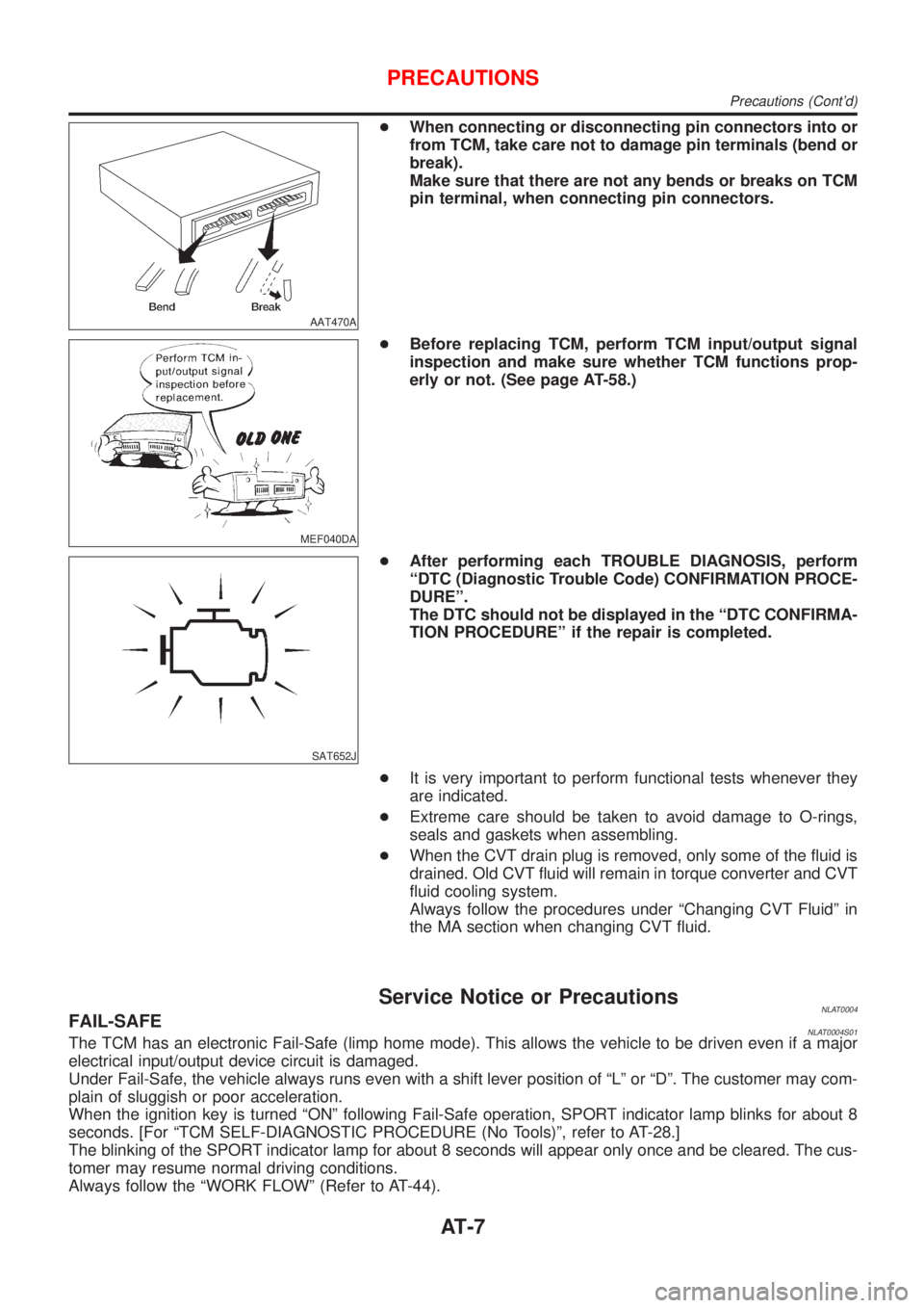
+When connecting or disconnecting pin connectors into or
from TCM, take care not to damage pin terminals (bend or
break).
Make sure that there are not any bends or breaks on TCM
pin terminal, when connecting pin connectors.
MEF040DA
+Before replacing TCM, perform TCM input/output signal
inspection and make sure whether TCM functions prop-
erly or not. (See page AT-58.)
SAT652J
+After performing each TROUBLE DIAGNOSIS, perform
ªDTC (Diagnostic Trouble Code) CONFIRMATION PROCE-
DUREº.
The DTC should not be displayed in the ªDTC CONFIRMA-
TION PROCEDUREº if the repair is completed.
+It is very important to perform functional tests whenever they
are indicated.
+Extreme care should be taken to avoid damage to O-rings,
seals and gaskets when assembling.
+When the CVT drain plug is removed, only some of the fluid is
drained. Old CVT fluid will remain in torque converter and CVT
fluid cooling system.
Always follow the procedures under ªChanging CVT Fluidº in
the MA section when changing CVT fluid.
Service Notice or PrecautionsNLAT0004FAIL-SAFENLAT0004S01The TCM has an electronic Fail-Safe (limp home mode). This allows the vehicle to be driven even if a major
electrical input/output device circuit is damaged.
Under Fail-Safe, the vehicle always runs even with a shift lever position of ªLº or ªDº. The customer may com-
plain of sluggish or poor acceleration.
When the ignition key is turned ªONº following Fail-Safe operation, SPORT indicator lamp blinks for about 8
seconds. [For ªTCM SELF-DIAGNOSTIC PROCEDURE (No Tools)º, refer to AT-28.]
The blinking of the SPORT indicator lamp for about 8 seconds will appear only once and be cleared. The cus-
tomer may resume normal driving conditions.
Always follow the ªWORK FLOWº (Refer to AT-44).
PRECAUTIONS
Precautions (Cont'd)
AT-7
Page 429 of 3051
Wiring Diagram ........................................................304
Diagnostic Procedure ..............................................306
Component Inspection .............................................308
DTC P0400 EGR FUNCTION (CLOSED) (WHERE
FITTED)........................................................................310
Description ...............................................................310
CONSULT-II Reference Value in Data Monitor
Mode ........................................................................ 311
ECM Terminals and Reference Value ..................... 311
On Board Diagnosis Logic....................................... 311
DTC Confirmation Procedure ..................................312
Wiring Diagram ........................................................314
Diagnostic Procedure ..............................................316
Component Inspection .............................................318
DTC P0403 EGR VOLUME CONTROL VALVE
(CIRCUIT) (WHERE FITTED)......................................319
Description ...............................................................319
CONSULT-II Reference Value in Data Monitor
Mode ........................................................................320
ECM Terminals and Reference Value .....................320
On Board Diagnosis Logic.......................................320
DTC Confirmation Procedure ..................................320
Wiring Diagram ........................................................322
Diagnostic Procedure ..............................................324
Component Inspection .............................................326
DTC P0420 THREE WAY CATALYST FUNCTION...327
On Board Diagnosis Logic.......................................327
DTC Confirmation Procedure ..................................327
Overall Function Check ...........................................328
Diagnostic Procedure ..............................................328
DTC P0443 EVAP CANISTER PURGE VOLUME
CONTROL SOLENOID VALVE (CIRCUIT).................332
Description ...............................................................332
CONSULT-II Reference Value in Data Monitor
Mode ........................................................................332
ECM Terminals and Reference Value .....................333
On Board Diagnosis Logic.......................................333
DTC Confirmation Procedure ..................................333
Wiring Diagram ........................................................334
Diagnostic Procedure ..............................................336
Component Inspection .............................................337
DTC P0500 VEHICLE SPEED SENSOR (VSS).........338
Component Description ...........................................338
ECM Terminals and Reference Value .....................338
On Board Diagnosis Logic.......................................338
DTC Confirmation Procedure ..................................338
Wiring Diagram ........................................................340
Diagnostic Procedure ..............................................342
DTC P0505 IDLE AIR CONTROL VALVE (IACV) -
AUXILIARY AIR CONTROL (AAC) VALVE...............343
Description ...............................................................343CONSULT-II Reference Value in Data Monitor
Mode ........................................................................344
ECM Terminals and Reference Value .....................344
On Board Diagnosis Logic.......................................344
DTC Confirmation Procedure ..................................344
Wiring Diagram ........................................................345
Diagnostic Procedure ..............................................347
Component Inspection .............................................351
DTC P0510 CLOSED THROTTLE POSITION
SWITCH (WHERE FITTED).........................................352
Component Description ...........................................352
CONSULT-II Reference Value in Data Monitor
Mode ........................................................................352
ECM Terminals and Reference Value .....................352
On Board Diagnosis Logic.......................................352
DTC Confirmation Procedure ..................................352
Overall Function Check ...........................................353
Wiring Diagram ........................................................354
Diagnostic Procedure ..............................................355
Component Inspection .............................................356
DTC P0605 ECM.........................................................358
Component Description ...........................................358
On Board Diagnosis Logic.......................................358
DTC Confirmation Procedure ..................................358
Diagnostic Procedure ..............................................359
D T C P 1111INTAKE VALVE TIMING CONTROL
SOLENOID VALVE......................................................360
Component Description ...........................................360
Operation .................................................................360
CONSULT-II Reference Value in Data Monitor
Mode ........................................................................360
ECM Terminals and Reference Value .....................360
On Board Diagnosis Logic.......................................360
DTC Confirmation Procedure ..................................361
Wiring Diagram ........................................................362
Diagnostic Procedure ..............................................364
Component Inspection .............................................365
DTC P1131 SWIRL CONTROL VALVE SOLENOID
VALVE (CIRCUIT) (WHERE FITTED).........................366
Description ...............................................................366
CONSULT-II Reference Value in Data Monitor
Mode ........................................................................366
ECM Terminals and Reference Value .....................367
Component Description ...........................................367
On Board Diagnosis Logic.......................................367
DTC Confirmation Procedure ..................................367
Wiring Diagram ........................................................369
Diagnostic Procedure ..............................................370
Component Inspection .............................................371
DTC P1217 OVERHEAT (COOLING SYSTEM).........373
System Description ..................................................373
CONTENTS(Cont'd)
EC-4
Page 435 of 3051
Component Inspection .............................................847
DTC P0420 THREE WAY CATALYST FUNCTION...848
On Board Diagnosis Logic.......................................848
DTC Confirmation Procedure ..................................848
Overall Function Check ...........................................849
Diagnostic Procedure ..............................................849
DTC P0443 EVAP CANISTER PURGE VOLUME
CONTROL SOLENOID VALVE (CIRCUIT).................852
Description ...............................................................852
CONSULT-II Reference Value in Data Monitor
Mode ........................................................................852
ECM Terminals and Reference Value .....................853
On Board Diagnosis Logic.......................................853
DTC Confirmation Procedure ..................................853
Wiring Diagram ........................................................854
Diagnostic Procedure ..............................................856
Component Inspection .............................................857
DTC P0500 VEHICLE SPEED SENSOR (VSS).........858
Component Description ...........................................858
ECM Terminals and Reference Value .....................858
On Board Diagnosis Logic.......................................858
DTC Confirmation Procedure ..................................858
Wiring Diagram ........................................................860
Diagnostic Procedure ..............................................862
DTC P0505 IDLE AIR CONTROL VALVE (IACV) -
AUXILIARY AIR CONTROL (AAC) VALVE...............863
Description ...............................................................863
CONSULT-II Reference Value in Data Monitor
Mode ........................................................................864
ECM Terminals and Reference Value .....................864
On Board Diagnosis Logic.......................................864
DTC Confirmation Procedure ..................................864
Wiring Diagram ........................................................865
Diagnostic Procedure ..............................................867
Component Inspection .............................................871
DTC P0510 CLOSED THROTTLE POSITION
SWITCH.......................................................................872
Component Description ...........................................872
CONSULT-II Reference Value in Data Monitor
Mode ........................................................................872
ECM Terminals and Reference Value .....................872
On Board Diagnosis Logic.......................................872
DTC Confirmation Procedure ..................................872
Overall Function Check ...........................................873
Wiring Diagram ........................................................874
Diagnostic Procedure ..............................................876
Component Inspection .............................................878
DTC P0605 ECM.........................................................880
Component Description ...........................................880
On Board Diagnosis Logic.......................................880
DTC Confirmation Procedure ..................................880
Diagnostic Procedure ..............................................881DTC P1217 OVERHEAT (COOLING SYSTEM).........882
System Description ..................................................882
CONSULT-II Reference Value in Data Monitor
Mode ........................................................................882
ECM Terminals and Reference Value .....................883
On Board Diagnosis Logic.......................................883
Overall Function Check ...........................................884
Wiring Diagram ........................................................885
Diagnostic Procedure ..............................................887
Main 12 Causes of Overheating..............................898
Component Inspection .............................................898
DTC P1320 IGNITION SIGNAL...................................900
Component Description ...........................................900
CONSULT-II Reference Value in Data Monitor
Mode ........................................................................900
ECM Terminals and Reference Value .....................900
On Board Diagnosis Logic.......................................901
DTC Confirmation Procedure ..................................901
Wiring Diagram ........................................................903
Diagnostic Procedure ..............................................905
Component Inspection .............................................907
DTC P1336 CRANKSHAFT POSITION SENSOR
(CKPS) (OBD) (COG)..................................................909
Component Description ...........................................909
ECM Terminals and Reference Value .....................909
On Board Diagnosis Logic.......................................910
DTC Confirmation Procedure ..................................910
Wiring Diagram ........................................................ 911
Diagnostic Procedure ..............................................913
Component Inspection .............................................914
DTC P1401 EGR TEMPERATURE SENSOR
(WHERE FITTED)........................................................915
Component Description ...........................................915
On Board Diagnosis Logic.......................................915
DTC Confirmation Procedure ..................................915
Wiring Diagram ........................................................918
Diagnostic Procedure ..............................................919
Component Inspection .............................................920
DTC P1402 EGR FUNCTION (OPEN) (WHERE
FITTED)........................................................................921
Description ...............................................................921
CONSULT-II Reference Value in Data Monitor
Mode ........................................................................922
ECM Terminals and Reference Value .....................922
On Board Diagnosis Logic.......................................922
DTC Confirmation Procedure ..................................923
Wiring Diagram ........................................................925
Diagnostic Procedure ..............................................926
DTC P1605 A/T DIAGNOSIS COMMUNICATION
LINE.............................................................................928
System Description ..................................................928
ECM Terminals and Reference Value .....................928
CONTENTS(Cont'd)
EC-10
Page 459 of 3051
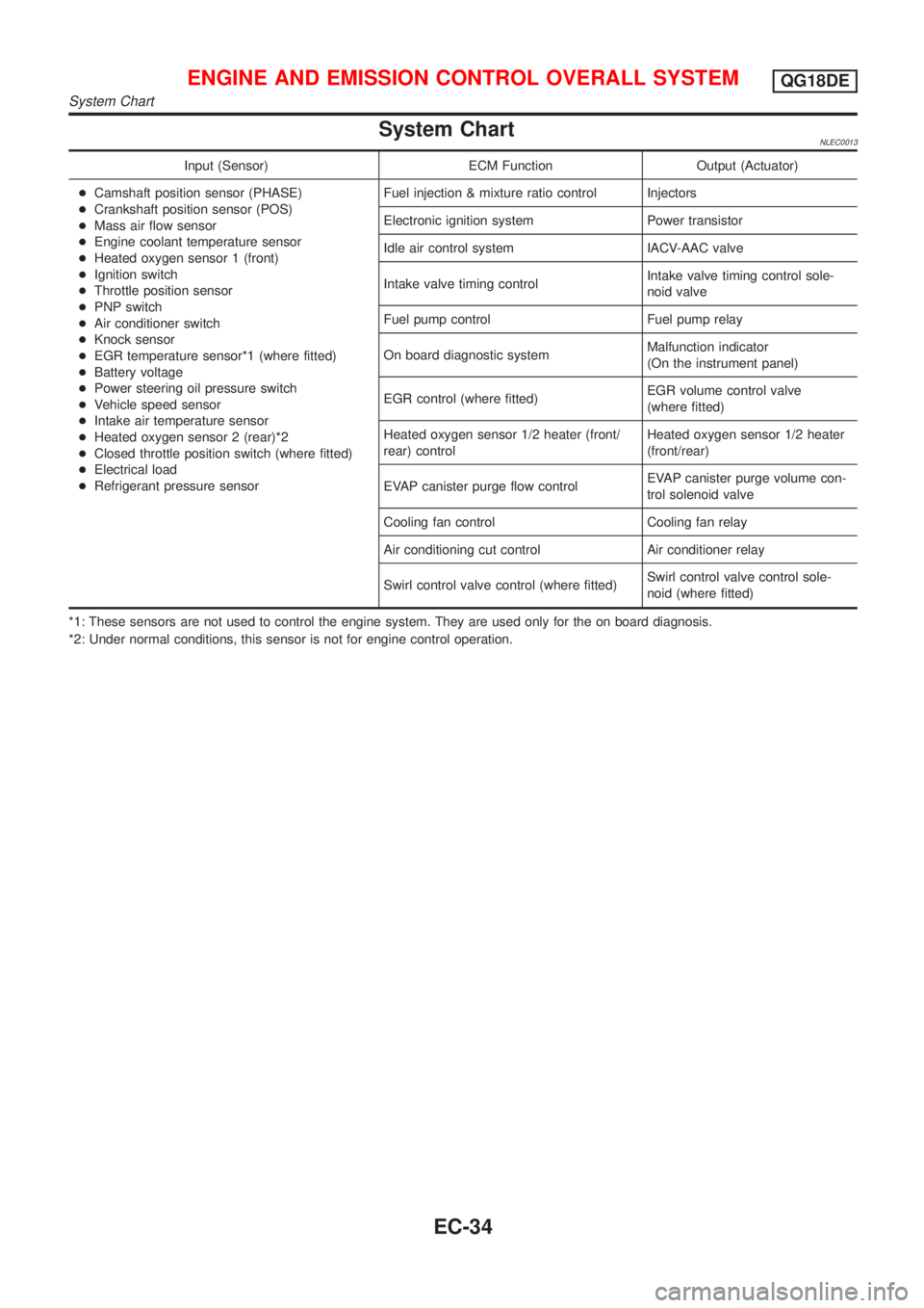
System ChartNLEC0013
Input (Sensor) ECM Function Output (Actuator)
+Camshaft position sensor (PHASE)
+Crankshaft position sensor (POS)
+Mass air flow sensor
+Engine coolant temperature sensor
+Heated oxygen sensor 1 (front)
+Ignition switch
+Throttle position sensor
+PNP switch
+Air conditioner switch
+Knock sensor
+EGR temperature sensor*1 (where fitted)
+Battery voltage
+Power steering oil pressure switch
+Vehicle speed sensor
+Intake air temperature sensor
+Heated oxygen sensor 2 (rear)*2
+Closed throttle position switch (where fitted)
+Electrical load
+Refrigerant pressure sensorFuel injection & mixture ratio control Injectors
Electronic ignition system Power transistor
Idle air control system IACV-AAC valve
Intake valve timing controlIntake valve timing control sole-
noid valve
Fuel pump control Fuel pump relay
On board diagnostic systemMalfunction indicator
(On the instrument panel)
EGR control (where fitted)EGR volume control valve
(where fitted)
Heated oxygen sensor 1/2 heater (front/
rear) controlHeated oxygen sensor 1/2 heater
(front/rear)
EVAP canister purge flow controlEVAP canister purge volume con-
trol solenoid valve
Cooling fan control Cooling fan relay
Air conditioning cut control Air conditioner relay
Swirl control valve control (where fitted)Swirl control valve control sole-
noid (where fitted)
*1: These sensors are not used to control the engine system. They are used only for the on board diagnosis.
*2: Under normal conditions, this sensor is not for engine control operation.
ENGINE AND EMISSION CONTROL OVERALL SYSTEMQG18DE
System Chart
EC-34
Page 472 of 3051
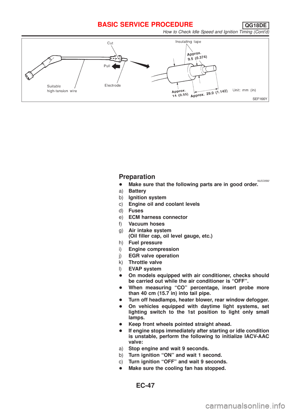
SEF166Y
PreparationNLEC0592+Make sure that the following parts are in good order.
a)Battery
b)Ignition system
c)Engine oil and coolant levels
d)Fuses
e)ECM harness connector
f)Vacuum hoses
g)Air intake system
(Oil filler cap, oil level gauge, etc.)
h)Fuel pressure
i)Engine compression
j)EGR valve operation
k)Throttle valve
l)EVAP system
+On models equipped with air conditioner, checks should
be carried out while the air conditioner is ªOFFº.
+When measuring ªCOº percentage, insert probe more
than 40 cm (15.7 in) into tail pipe.
+Turn off headlamps, heater blower, rear window defogger.
+On vehicles equipped with daytime light systems, set
lighting switch to the 1st position to light only small
lamps.
+Keep front wheels pointed straight ahead.
+If engine stops immediately after starting or idle condition
is unstable, perform the following to initialize IACV-AAC
valve:
a)Stop engine and wait 9 seconds.
b)Turn ignition ªONº and wait 1 second.
c)Turn ignition ªOFFº and wait 9 seconds.
+Make sure the cooling fan has stopped.
BASIC SERVICE PROCEDUREQG18DE
How to Check Idle Speed and Ignition Timing (Cont'd)
EC-47
Page 482 of 3051
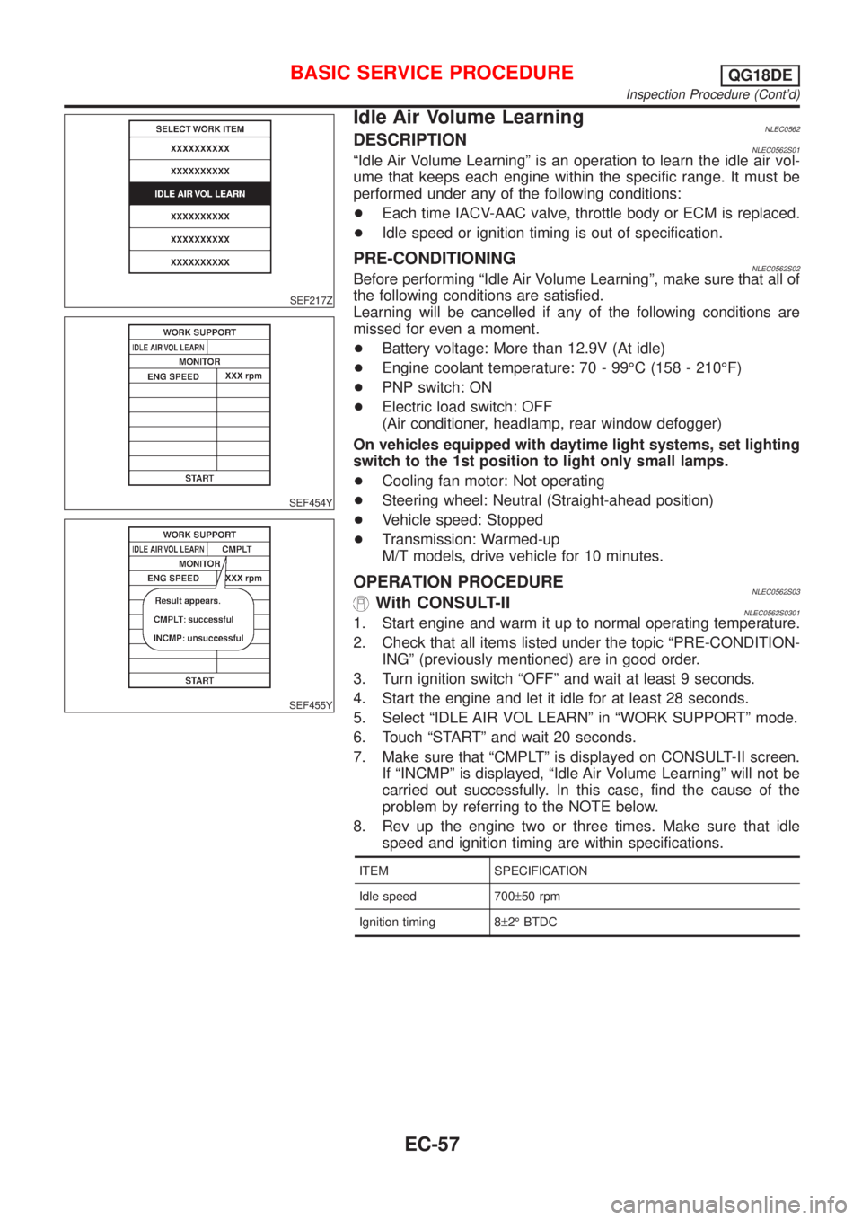
SEF217Z
SEF454Y
SEF455Y
Idle Air Volume LearningNLEC0562DESCRIPTIONNLEC0562S01ªIdle Air Volume Learningº is an operation to learn the idle air vol-
ume that keeps each engine within the specific range. It must be
performed under any of the following conditions:
+Each time IACV-AAC valve, throttle body or ECM is replaced.
+Idle speed or ignition timing is out of specification.
PRE-CONDITIONINGNLEC0562S02Before performing ªIdle Air Volume Learningº, make sure that all of
the following conditions are satisfied.
Learning will be cancelled if any of the following conditions are
missed for even a moment.
+Battery voltage: More than 12.9V (At idle)
+Engine coolant temperature: 70 - 99ÉC (158 - 210ÉF)
+PNP switch: ON
+Electric load switch: OFF
(Air conditioner, headlamp, rear window defogger)
On vehicles equipped with daytime light systems, set lighting
switch to the 1st position to light only small lamps.
+Cooling fan motor: Not operating
+Steering wheel: Neutral (Straight-ahead position)
+Vehicle speed: Stopped
+Transmission: Warmed-up
M/T models, drive vehicle for 10 minutes.
OPERATION PROCEDURENLEC0562S03With CONSULT-IINLEC0562S03011. Start engine and warm it up to normal operating temperature.
2. Check that all items listed under the topic ªPRE-CONDITION-
INGº (previously mentioned) are in good order.
3. Turn ignition switch ªOFFº and wait at least 9 seconds.
4. Start the engine and let it idle for at least 28 seconds.
5. Select ªIDLE AIR VOL LEARNº in ªWORK SUPPORTº mode.
6. Touch ªSTARTº and wait 20 seconds.
7. Make sure that ªCMPLTº is displayed on CONSULT-II screen.
If ªINCMPº is displayed, ªIdle Air Volume Learningº will not be
carried out successfully. In this case, find the cause of the
problem by referring to the NOTE below.
8. Rev up the engine two or three times. Make sure that idle
speed and ignition timing are within specifications.
ITEM SPECIFICATION
Idle speed 700±50 rpm
Ignition timing 8±2É BTDC
BASIC SERVICE PROCEDUREQG18DE
Inspection Procedure (Cont'd)
EC-57
Page 509 of 3051
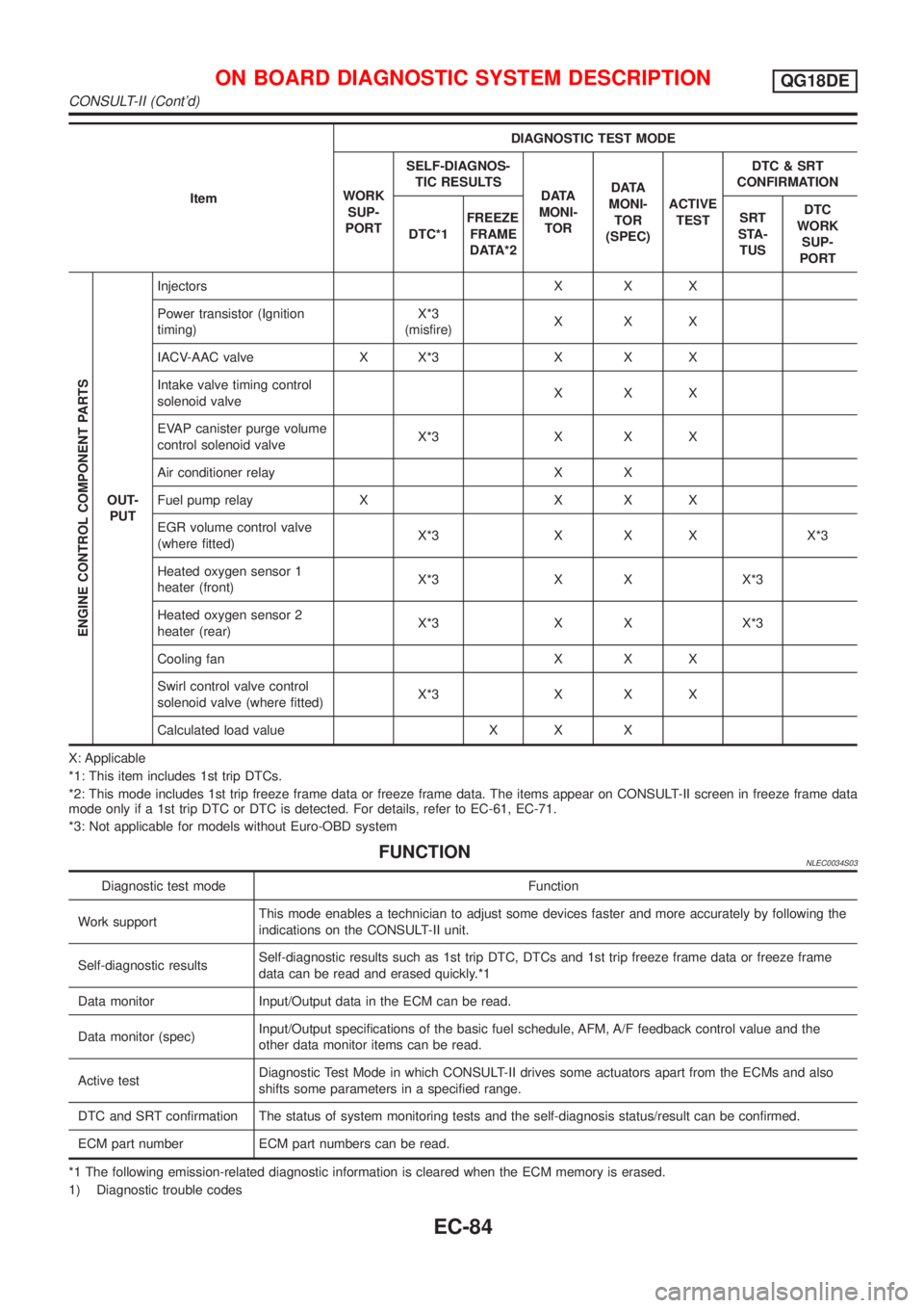
ItemDIAGNOSTIC TEST MODE
WORK
SUP-
PORTSELF-DIAGNOS-
TIC RESULTS
D ATA
MONI-
TORD ATA
MONI-
TOR
(SPEC)ACTIVE
TESTDTC & SRT
CONFIRMATION
DTC*1FREEZE
FRAME
DATA*2SRT
STA-
TUSDTC
WORK
SUP-
PORT
ENGINE CONTROL COMPONENT PARTS
OUT-
PUTInjectors X X X
Power transistor (Ignition
timing)X*3
(misfire)XXX
IACV-AAC valve X X*3 X X X
Intake valve timing control
solenoid valveXXX
EVAP canister purge volume
control solenoid valveX*3 X X X
Air conditioner relay X X
Fuel pump relay X X X X
EGR volume control valve
(where fitted)X*3 X X X X*3
Heated oxygen sensor 1
heater (front)X*3 X X X*3
Heated oxygen sensor 2
heater (rear)X*3 X X X*3
Cooling fan X X X
Swirl control valve control
solenoid valve (where fitted)X*3 X X X
Calculated load value X X X
X: Applicable
*1: This item includes 1st trip DTCs.
*2: This mode includes 1st trip freeze frame data or freeze frame data. The items appear on CONSULT-II screen in freeze frame data
mode only if a 1st trip DTC or DTC is detected. For details, refer to EC-61, EC-71.
*3: Not applicable for models without Euro-OBD system
FUNCTIONNLEC0034S03
Diagnostic test mode Function
Work supportThis mode enables a technician to adjust some devices faster and more accurately by following the
indications on the CONSULT-II unit.
Self-diagnostic resultsSelf-diagnostic results such as 1st trip DTC, DTCs and 1st trip freeze frame data or freeze frame
data can be read and erased quickly.*1
Data monitor Input/Output data in the ECM can be read.
Data monitor (spec)Input/Output specifications of the basic fuel schedule, AFM, A/F feedback control value and the
other data monitor items can be read.
Active testDiagnostic Test Mode in which CONSULT-II drives some actuators apart from the ECMs and also
shifts some parameters in a specified range.
DTC and SRT confirmation The status of system monitoring tests and the self-diagnosis status/result can be confirmed.
ECM part number ECM part numbers can be read.
*1 The following emission-related diagnostic information is cleared when the ECM memory is erased.
1) Diagnostic trouble codes
ON BOARD DIAGNOSTIC SYSTEM DESCRIPTIONQG18DE
CONSULT-II (Cont'd)
EC-84
Page 513 of 3051
![NISSAN ALMERA TINO 2001 Service Repair Manual Monitored item [Unit]ECM
input
signalsMain
signalsDescription Remarks
CAL/LD VALUE [%]+ªCalculated load valueº indicates the value of
the current airflow divided by peak airflow.
ABSOL TH.P/S [%]+ª NISSAN ALMERA TINO 2001 Service Repair Manual Monitored item [Unit]ECM
input
signalsMain
signalsDescription Remarks
CAL/LD VALUE [%]+ªCalculated load valueº indicates the value of
the current airflow divided by peak airflow.
ABSOL TH.P/S [%]+ª](/img/5/57352/w960_57352-512.png)
Monitored item [Unit]ECM
input
signalsMain
signalsDescription Remarks
CAL/LD VALUE [%]+ªCalculated load valueº indicates the value of
the current airflow divided by peak airflow.
ABSOL TH.P/S [%]+ªAbsolute throttle position sensorº indicates
the throttle opening computed by ECM
according to the signal voltage of the throttle
position sensor.
MASS AIRFLOW
[gm/s]+Indicates the mass airflow computed by ECM
according to the signal voltage of the mass
air flow sensor.
IACV-AAC/V [step]j+Indicates the IACV-AAC valve control value
computed by ECM according to the input sig-
nals.
PURG VOL C/V [%]+Indicates the EVAP canister purge volume
control solenoid valve computed by the ECM
according to the inpuct signals.
+The opening becomes larger as the value
increases.
EGR VOL CON/V
[step]
(where fitted)j+Indicates the EGR volume control valve com-
puted by the ECM according to the input sig-
nals.
+The opening becomes larger as the value
increases.
SWRL CONT S/V
[ON/OFF]
(where fitted)+The control condition of the swirl control
valve control solenoid valve (determined by
ECM according to the input signals) is indi-
cated.
+ON ... Swirl control valve is closed.
OFF ... Swirl control valve is opened.
INT/V SOL-B1
[ON/OFF]+The control condition of the valve timing sole-
noid valve (determined by ECM according to
the input signal) is indicated.
ON ... Intake valve timing control operating
OFF ... Intake valve timing control not operat-
ing
AIR COND RLY
[ON/OFF]j+Indicates the air conditioner relay control con-
dition determined by ECM according to the
input signals.
FUEL PUMP RLY
[ON/OFF]j+Indicates the fuel pump relay control condi-
tion determined by ECM according to the
input signals.
COOLING FAN
[ON/OFF]j+Indicates [ON/OFF] control condition of the
cooling fan determined by ECM according to
the input signals.
HO2S1 HTR (B1)
[ON/OFF]+Indicates [ON/OFF] condition of heated oxy-
gen sensor 1 heater (front) determined by
ECM according to the input signals.
HO2S2 HTR (B1)
[ON/OFF]+Indicates [ON/OFF] condition of heated oxy-
gen sensor 2 heater (rear) determined by
ECM according to the input signals.
ON BOARD DIAGNOSTIC SYSTEM DESCRIPTIONQG18DE
CONSULT-II (Cont'd)
EC-88
Page 515 of 3051
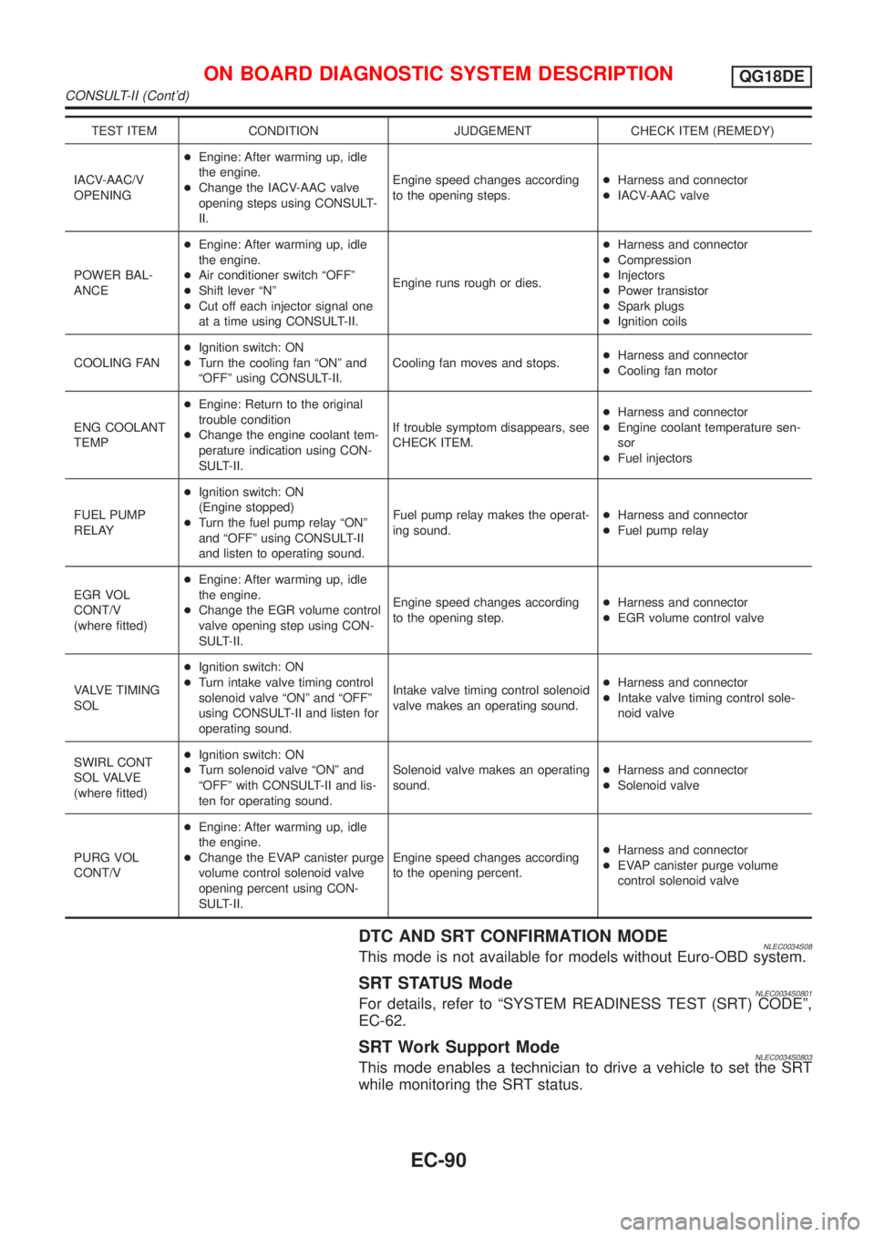
TEST ITEM CONDITION JUDGEMENT CHECK ITEM (REMEDY)
IACV-AAC/V
OPENING+Engine: After warming up, idle
the engine.
+Change the IACV-AAC valve
opening steps using CONSULT-
II.Engine speed changes according
to the opening steps.+Harness and connector
+IACV-AAC valve
POWER BAL-
ANCE+Engine: After warming up, idle
the engine.
+Air conditioner switch ªOFFº
+Shift lever ªNº
+Cut off each injector signal one
at a time using CONSULT-II.Engine runs rough or dies.+Harness and connector
+Compression
+Injectors
+Power transistor
+Spark plugs
+Ignition coils
COOLING FAN+Ignition switch: ON
+Turn the cooling fan ªONº and
ªOFFº using CONSULT-II.Cooling fan moves and stops.+Harness and connector
+Cooling fan motor
ENG COOLANT
TEMP+Engine: Return to the original
trouble condition
+Change the engine coolant tem-
perature indication using CON-
SULT-II.If trouble symptom disappears, see
CHECK ITEM.+Harness and connector
+Engine coolant temperature sen-
sor
+Fuel injectors
FUEL PUMP
RELAY+Ignition switch: ON
(Engine stopped)
+Turn the fuel pump relay ªONº
and ªOFFº using CONSULT-II
and listen to operating sound.Fuel pump relay makes the operat-
ing sound.+Harness and connector
+Fuel pump relay
EGR VOL
CONT/V
(where fitted)+Engine: After warming up, idle
the engine.
+Change the EGR volume control
valve opening step using CON-
SULT-II.Engine speed changes according
to the opening step.+Harness and connector
+EGR volume control valve
VALVE TIMING
SOL+Ignition switch: ON
+Turn intake valve timing control
solenoid valve ªONº and ªOFFº
using CONSULT-II and listen for
operating sound.Intake valve timing control solenoid
valve makes an operating sound.+Harness and connector
+Intake valve timing control sole-
noid valve
SWIRL CONT
S O L VA LV E
(where fitted)+Ignition switch: ON
+Turn solenoid valve ªONº and
ªOFFº with CONSULT-II and lis-
ten for operating sound.Solenoid valve makes an operating
sound.+Harness and connector
+Solenoid valve
PURG VOL
CONT/V+Engine: After warming up, idle
the engine.
+Change the EVAP canister purge
volume control solenoid valve
opening percent using CON-
SULT-II.Engine speed changes according
to the opening percent.+Harness and connector
+EVAP canister purge volume
control solenoid valve
DTC AND SRT CONFIRMATION MODENLEC0034S08This mode is not available for models without Euro-OBD system.
SRT STATUS ModeNLEC0034S0801For details, refer to ªSYSTEM READINESS TEST (SRT) CODEº,
EC-62.
SRT Work Support ModeNLEC0034S0803This mode enables a technician to drive a vehicle to set the SRT
while monitoring the SRT status.
ON BOARD DIAGNOSTIC SYSTEM DESCRIPTIONQG18DE
CONSULT-II (Cont'd)
EC-90