clock NISSAN ALMERA TINO 2001 Service Owner's Manual
[x] Cancel search | Manufacturer: NISSAN, Model Year: 2001, Model line: ALMERA TINO, Model: NISSAN ALMERA TINO 2001Pages: 3051, PDF Size: 46.38 MB
Page 1927 of 3051

Wiring Diagram Ð CLOCK ÐNLEL0462MODELS WITH FUSE AND FUSIBLE LINK BOX E43NLEL0462S01
YEL910B
CLOCK
Wiring Diagram Ð CLOCK Ð
EL-196
Page 1928 of 3051

MODELS WITH FUSE AND FUSIBLE LINK BOX E90NLEL0462S02
YEL543C
CLOCK
Wiring Diagram Ð CLOCK Ð (Cont'd)
EL-197
Page 2137 of 3051

ªHISTORY OF ERRORSº TABLE=NLEL0516S02
Detected items Description Diagnosis/service procedureRefer-
ence
page
Gyro sensor disconnectedCommunications malfunction between
NAVI control unit and internal gyroPerform self-diagnosis to confirm
whether the NAVI control unit is mal-
functioning or not. If no failure is
detected, a momentary and/or tempo-
rary malfunction may have been caused
by strong electromagnetic wave interfer-
ence.EL-401
Connection problem of speed
sensorInput malfunction of NAVI control unit
and speed sensorCheck vehicle speed sensor signal in
ªDiagnosis for signals from the carº
mode. If the input signal is not detected
correctly, check harness for open or
short between combination meter and
NAVI control unit.EL-408
GPS disconnected
Communications malfunction between
NAVI control unit and GPS boardPerform self-diagnosis to confirm
whether the NAVI control unit is mal-
functioning or not. If no failure is
detected, a momentary and/or tempo-
rary malfunction may have been caused
by strong electromagnetic wave interfer-
ence.EL-401 GPS transmission cable malfunc-
tion
GPS input line connection error
GPS TCXO overThe transmission circuit of the GPS
board frequency synchronization oscilla-
tor (inside the NAVI control unit) is send-
ing an oscillation frequency that is
greater or less than the set value.A location error occurs. Strong electro-
magnetic wave interference may have
occurred. The GPS antenna may be in a
very hot or very cold environment. This
is usually a temporary malfunction.Ð
GPS TCXO under
GPS ROM malfunction
Internal malfunction of GPS board RAM
or ROM inside the NAVI control unit.Perform self-diagnosis to confirm
whether the NAVI control unit is mal-
functioning or not. If no failure is
detected, a momentary and/or tempo-
rary malfunction may have been caused
by strong electromagnetic wave interfer-
ence.EL-401 GPS RAM malfunction
GPS RTC malfunctionMalfunction of GPS board clock IC
inside the NAVI control unit.
GPS antenna disconnected ÐPerform self-diagnosis to confirm GPS
antenna connection. If no failure is
detected, a momentary and/or tempo-
rary malfunction may have been caused
by a strong impact.EL-401
Low voltage of GPSPower supply voltage for GPS board
inside the NAVI control unit is low.1. Check power supply circuits for NAVI
control unit.EL-429
2. Perform self-diagnosis to confirm
GPS antenna connection.EL-401
3. If above diagnosis results are OK, a
momentary and/or temporary malfunc-
tion may have been caused by a strong
impact.Ð
CD-ROM communication errorCD-ROM driver malfunction (inside the
NAVI control unit)Perform self-diagnosis to confirm
whether the NAVI control unit is mal-
functioning or not. If no failure is
detected, a momentary and/or tempo-
rary malfunction may have been caused
by strong electromagnetic wave interfer-
ence.EL-401
NAVIGATION SYSTEM
Confirmation/Adjustment Mode (Cont'd)
EL-406
Page 2256 of 3051
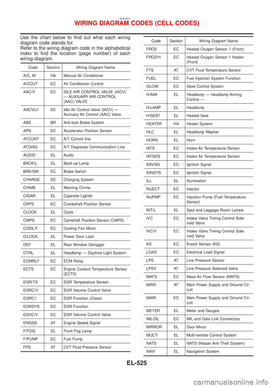
NLEL0311
Use the chart below to find out what each wiring
diagram code stands for.
Refer to the wiring diagram code in the alphabetical
index to find the location (page number) of each
wiring diagram.
Code Section Wiring Diagram Name
A/C, M HA Manual Air Conditioner
A/CCUT EC Air Conditioner Control
AAC/V EC IDLE AIR CONTROL VALVE (IACV)
Ð AUXIUARY AIR CONTROL
(AAC) VALVE
AACVLV EC Idle Air Control Valve (IACV) Ð
Auxiuary Air Control (AAC) Valve
ABS BR Anti-lock Brake System
APS EC Accelerator Position Sensor
ATCONT EC A/T Control line
ATDIAG EC A/T Diagnosis Communication Line
AUDIO EL Audio
BACK/L EL Back-up Lamp
BRK/SW EC Brake Switch
CHARGE SC Charging System
CHIME EL Warning Chime
CIGAR EL Cigarette Lighter
CKPS EC Crankshaft Position Sensor
CLOCK EL Clock
CMPS EC Camshaft Position Sensor (CMPS)
COOL/F EC Cooling Fan Motor
D/LOCK EL Power Door Lock
DEF EL Rear Window Defogger
DTRL EL Headlamp Ð Daytime Light System
ECMRLY EC ECM Relay
ECTS EC Engine Coolant Temperature Sensor
(ECTS)
EGR/TS EC EGR Temperature Sensor
EGRC/V EC EGR Volume Control Valve
EGRC1 EC EGR Function (Close)
EGRSYS EC EGR Function
EGVC/V EC EGR Volume Control Valve
ENGSS AT Engine Speed Signal
F/FOG EL Front Fog Lamp
F/PUMP EC Fuel Pump
FPS AT CVT Fluid Pressure Sensor
Code Section Wiring Diagram Name
FRO2 EC Heated Oxygen Sensor 1 (Front)
FRO2/H EC Heated Oxygen Sensor 1 Heater
(Front)
FTS AT CVT Fluid Temperature Sensor
FUEL EC Fuel Injection System Function
GLOW EC Glow Control System
H/AIM EL Headlamp Ð Headlamp Aiming
Control Ð
H/LAMP EL Headlamp
H/SEAT EL Heated Seat
HEATER HA Heater System
HLC EL Headlamp Washer
HORN EL Horn
IATS EC Intake Air Temperature Sensor
IATSEN EC Intake Air Temperature Sensor
IGN/SG EC Ignition Signal
IGNSYS EC Ignition Signal
ILL EL Illumination
INJECT EC Injector
INJPMP EC Injection Pump (Fuel Temperature
Sensor)
INT/L EL Spot and Laggage Room Lamps
IVC EC Intake Valve Timing Control Sole-
noid Valve
IVC/V EC Intake Valve Timing Control Sole-
noid Valve
KS EC Knock Sensor (KS)
LOAD EC Electrical Load Signal
LPS AT Line Pressure Sensor
LPSV AT Line Pressure Solenoid Valve
MAFS EC Mass Air Flow Sensor (MAFS)
MAIN AT Main Power Supply and Ground Cir-
cuit
MAIN EC Main Power Supply and Ground Cir-
cuit
METER EL Meter and Gauges
MIL/DL EC MIL and Data Link Connectors
MIRROR EL Door Mirror
MULTI EL Multi-remote Control System
NATS EL NATS (Nissan Anti-Theft System)
NAVI EL Navigation System
WIRING DIAGRAM CODES (CELL CODES)
EL-525
Page 2284 of 3051

SEM886F
InstallationNLEM01071. Install crankshaft sprocket on crankshaft.
+Make sure mating marks on crankshaft sprocket face front
of engine.
SEM890F
2. Position crankshaft so that No. 1 piston is at TDC and key way
is at 12 o'clock.
SEM891F
3. Install slack side timing chain guide and timing chain tension
guide.
SEM892F
4. Install timing chain on crankshaft sprocket.
+Support chain with a suitable tool to keep the mating mark
aligned.
+Set timing chain by aligning its mating mark with that on
the crankshaft sprocket.
+Make sure sprocket's mating mark faces engine front.
SEM905F
5. Install camshaft sprocket.
+Set timing chain by aligning mating marks with those of
camshaft sprockets.
TIMING CHAINQG
Installation
EM-27
Page 2303 of 3051

SEM900F
SEM614EC
SEM901F
+Tightening procedure
a. Tighten bolts to 29 N´m (3 kg-m, 22 ft-lb).
b. Tighten bolts to 59 N´m (6 kg-m, 43 ft-lb).
c. Loosen bolts completely.
d. Tighten bolts to 29 N´m (3 kg-m, 22 ft-lb).
e. Turn bolts 50 to 55 degrees clockwise or if angle wrench
is not available, tighten bolts to 59±4.9 N´m (6±0.5 kg-m,
43±3.6 ft-lb).
f. Tightening bolts (11 - 14) to 6.3 to 8.3 N´m (0.64 to 0.85
kg-m, 55.8 to 73.5 in-lb).
Tightening torque N´m (kg-m, ft-lb)
abcde,f
Bolts
(1-10)29
(3, 22)59
(6, 43)0
(0, 0)29
(3, 22)50-55
degrees or
59±4.9
(6±0.5,
43±3.6
ft-lb)
Bolts
(11-14)ÐÐÐÐ6.3 - 8.3
(0.64 -
0.85, 55.8 -
73.5 in-lb)
4. Install camshaft.
+The camshafts are distinguished by a paint mark as follows.
Intake camshaft: Other paint color than white
Exhaust camshaft: White paint or no paint
SEM902F
+Make sure camshafts are aligned as shown in figure.
SEM903F
5. Install camshaft brackets.
+Make sure camshaft brackets are aligned as marked dur-
ing disassembly.
CYLINDER HEADQG
Installation (Cont'd)
EM-46
Page 2319 of 3051

SEM116F
4. Measure crankshaft end play.
Crankshaft end play:
Standard
0.060 - 0.260 mm (0.0024 - 0.0102 in)
Limit
0.3 mm (0.012 in)
If beyond the limit, replace thrust bearing with new ones.
SEM168D
5. Install connecting rod bearings in connecting rods and con-
necting rod caps.
+Confirm that correct bearings are used. Refer to EM-58.
+Install bearings so that oil hole in connecting rod aligns
with oil hole of bearing.
+Apply new engine oil to bolt threads and bearing surfaces.
SEM942F
6. Install pistons with connecting rods.
a. Install them into corresponding cylinders with Tool.
+Make sure connecting rod does not scratch cylinder wall.
+Make sure connecting rod bolts do not scratch crankshaft
pin journals.
+Arrange so that front mark on piston head faces engine.
+Apply new engine oil to piston rings and sliding surface
of piston.
SEM943F
b. Install connecting rod caps.
Apply new engine oil to bolt threads and nut seating surfaces.
Tighten connecting rod cap nuts in the following procedure:
+Tighten to 13.72 to 15.68 N´m (1.399 to 1.599 kg-m, 10.120
to 11.566 ft-lb).
+Turn nuts to 35É to 40É degrees clockwise with an angle
wrench. If an angle wrench is not available, tighten nuts to
23 to 28 N´m (2.3 to 2.9 kg-m, 17 to 21 ft-lb).
SEM935F
7. Measure connecting rod side clearance.
Connecting rod side clearance:
Standard
0.200 - 0.470 mm (0.0079 - 0.0185 in)
Limit
0.5 mm (0.020 in)
If beyond the limit, replace connecting rod and/or crank-
shaft.
CYLINDER BLOCKQG
Assembly (Cont'd)
EM-62
Page 2357 of 3051

SEM982CA
24. Remove timing chain guides.
SEM034G
25. Remove camshaft sprockets.
+For retiming, apply paint mark to timing chain matched
with mating marks of camshaft sprockets.
26. Remove timing chain and crankshaft sprocket.
SEM984C
InspectionNLEM0127Check for cracks and excessive wear at roller links. Replace
chain if necessary.
SEM470E
InstallationNLEM01281. Install crankshaft sprocket on crankshaft.
+Make sure mating marks on crankshaft sprocket face front
of engine.
SEM985C
2. Position crankshaft so that No. 1 piston is set at TDC and key
way is at 12 oclock. Fit timing chain on crankshaft sprocket,
aligning the mating marks.
TIMING CHAINSR
Removal (Cont'd)
EM-100
Page 2381 of 3051

SEM390G
SEM877A
2. Install cylinder head completely with intake and exhaust mani-
folds.
+Apply engine oil to threads and seating surfaces of cylin-
der head bolts before installing them.
+Be sure to install washers between bolts and cylinder
head.
Cylinder head bolts are tightened by plastic zone tightening
method. Whenever the size difference between d1 and d2
exceeds the limit, replace them with new ones.
Limit (d1 - d2):
0.15 mm (0.0059 in)
+If reduction of outer diameter appears in a position other than
d2, use it as d2 point.
SEM986C
3. Tighten cylinder head bolts using the following procedure.
a.Tighten all bolts to 39 N´m (4.0 kg-m, 29 ft-lb).
b.Tighten all bolts to 78 N´m (8.0 kg-m, 58 ft-lb).
c.Loosen all bolts completely.
d.Tighten all bolts to 39 N´m (4.0 kg-m, 29 ft-lb).
SEM043G
SEM044G
e.Method A:
Turn all bolts 90 to 95 degrees clockwise with Tool or
suitable angle wrench.
Method B:
If an angle wrench is not available, mark all cylinder head
bolts on the side facing engine front. Then, turn each cyl-
inder head bolt 90 to 95 degrees clockwise.
f.Turn all bolts another 90 to 95 degrees clockwise.
g.Ensure that paint mark on each bolt faces the rear of the
engine. (Method B only)
Do not turn any bolt 180 to 190 degrees clockwise all at once.
CYLINDER HEADSR
Installation (Cont'd)
EM-124
Page 2382 of 3051

AEM113
Tightening torque N´m (kg-m, ft-lb)
a. 39 (4.0, 29)
b. 78 (8.0, 58)
c. 0 (0, 0)
d. 39 (4.0, 29)
e. 90 - 95 degrees (90 degrees preferred)
f. 90 - 95 degrees (90 degrees preferred)
SEM037G
4. Install cylinder head outside bolts.
5. Install the following water hoses:
+Water hose for cylinder block.
+Water hoses for heater.
SEM036G
6. Install starter motor.
BEM004
7. Remove old liquid gasket from mating surface of LH camshaft
end bracket.
+Also remove old liquid gasket from mating surface of cyl-
inder head.
8. Apply liquid gasket to mating surface of LH camshaft end
bracket as shown in illustration.
+Use Genuine RTV silicone sealant part No. 999MP-A7007
or equivalent.
SEM045G
9. Install camshafts, camshaft brackets.
+Position camshaft.
+LH camshaft key at about 12 o'clock.
+RH camshaft key at about 10 o'clock.
Apply new engine oil to bearing and cam surfaces of cam-
shafts before installing them.
CYLINDER HEADSR
Installation (Cont'd)
EM-125