fuse chart NISSAN ALMERA TINO 2001 Service Repair Manual
[x] Cancel search | Manufacturer: NISSAN, Model Year: 2001, Model line: ALMERA TINO, Model: NISSAN ALMERA TINO 2001Pages: 3051, PDF Size: 46.38 MB
Page 306 of 3051

Malfunction Code/Symptom ChartNLBR0097MODELS WITH SELF-DIAGNOSIS FUNCTION (DATA LINK CONNECTOR TERMINAL NO. 9)NLBR0097S01
Code No. (No. of LED flashes) Malfunctioning part Reference page
12 Self-diagnosis could not detect any malfunctions.—
18 Sensor rotor BR-71
21 Front right sensor (open-circuit) BR-71
22 Front right sensor (short-circuit) BR-71
25 Front left sensor (open-circuit) BR-71
26 Front left sensor (short-circuit) BR-71
31 Rear right sensor (open-circuit) BR-71
32 Rear right sensor (short-circuit) BR-71
35 Rear left sensor (open-circuit) BR-71
36 Rear left sensor (short-circuit) BR-71
41 Actuator front right outlet solenoid valve BR-74
42 Actuator front right inlet solenoid valve BR-74
45 Actuator front left outlet solenoid valve BR-74
46 Actuator front left inlet solenoid valve BR-74
51 Actuator rear right outlet solenoid valve BR-74
52 Actuator rear right inlet solenoid valve BR-74
55 Actuator rear left outlet solenoid valve BR-74
56 Actuator rear left inlet solenoid valve BR-74
57* Power supply (Low voltage) BR-79
61 Actuator motor or motor relay BR-77
63 Solenoid valve relay BR-74
71 Control unit BR-81
ABS warning lamp stays on when
ignition switch is turned on.Control unit power supply circuit
Warning lamp bulb circuit
Control unit or control unit connector
Solenoid valve relay stuck
Power supply for solenoid valve relay coilBR-88
ABS warning lamp stays on, during
self-diagnosis.Control unit—
ABS warning lamp does not come on
when ignition switch is turned on.Fuse, warning lamp bulb or warning lamp circuit
Control unitBR-86
ABS warning lamp does not come on
during self-diagnosis.Control unit—
Pedal vibration and noise—BR-85
Long stopping distance—BR-83
Unexpected pedal action—BR-82
ABS does not work.—BR-84
ABS works frequently.—BR-82
*: Under voltage that is too low, the control unit disable the ABS. It does not set the ABS in fail-safe condition. Instead, the ABS becomes
TROUBLE DIAGNOSIS—GENERAL DESCRIPTIONABS
Malfunction Code/Symptom Chart
BR-69
Page 2082 of 3051

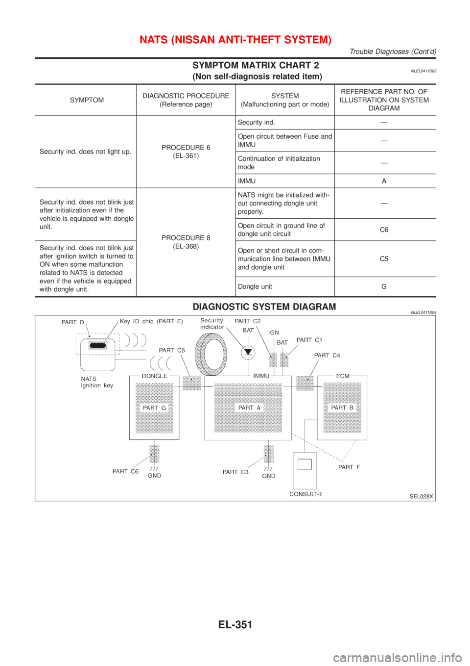
SYMPTOM MATRIX CHART 2NLEL0411S03(Non self-diagnosis related item)
SYMPTOMDIAGNOSTIC PROCEDURE
(Reference page)SYSTEM
(Malfunctioning part or mode)REFERENCE PART NO. OF
ILLUSTRATION ON SYSTEM
DIAGRAM
Security ind. does not light up.PROCEDURE 6
(EL-361)Security ind. Ð
Open circuit between Fuse and
IMMUÐ
Continuation of initialization
modeÐ
IMMU A
Security ind. does not blink just
after initialization even if the
vehicle is equipped with dongle
unit.
PROCEDURE 8
(EL-368)NATS might be initialized with-
out connecting dongle unit
properly.Ð
Open circuit in ground line of
dongle unit circuitC6
Security ind. does not blink just
after ignition switch is turned to
ON when some malfunction
related to NATS is detected
even if the vehicle is equipped
with dongle unit.Open or short circuit in com-
munication line between IMMU
and dongle unitC5
Dongle unit G
DIAGNOSTIC SYSTEM DIAGRAMNLEL0411S04
SEL028X
NATS (NISSAN ANTI-THEFT SYSTEM)
Trouble Diagnoses (Cont'd)
EL-351
Page 2084 of 3051

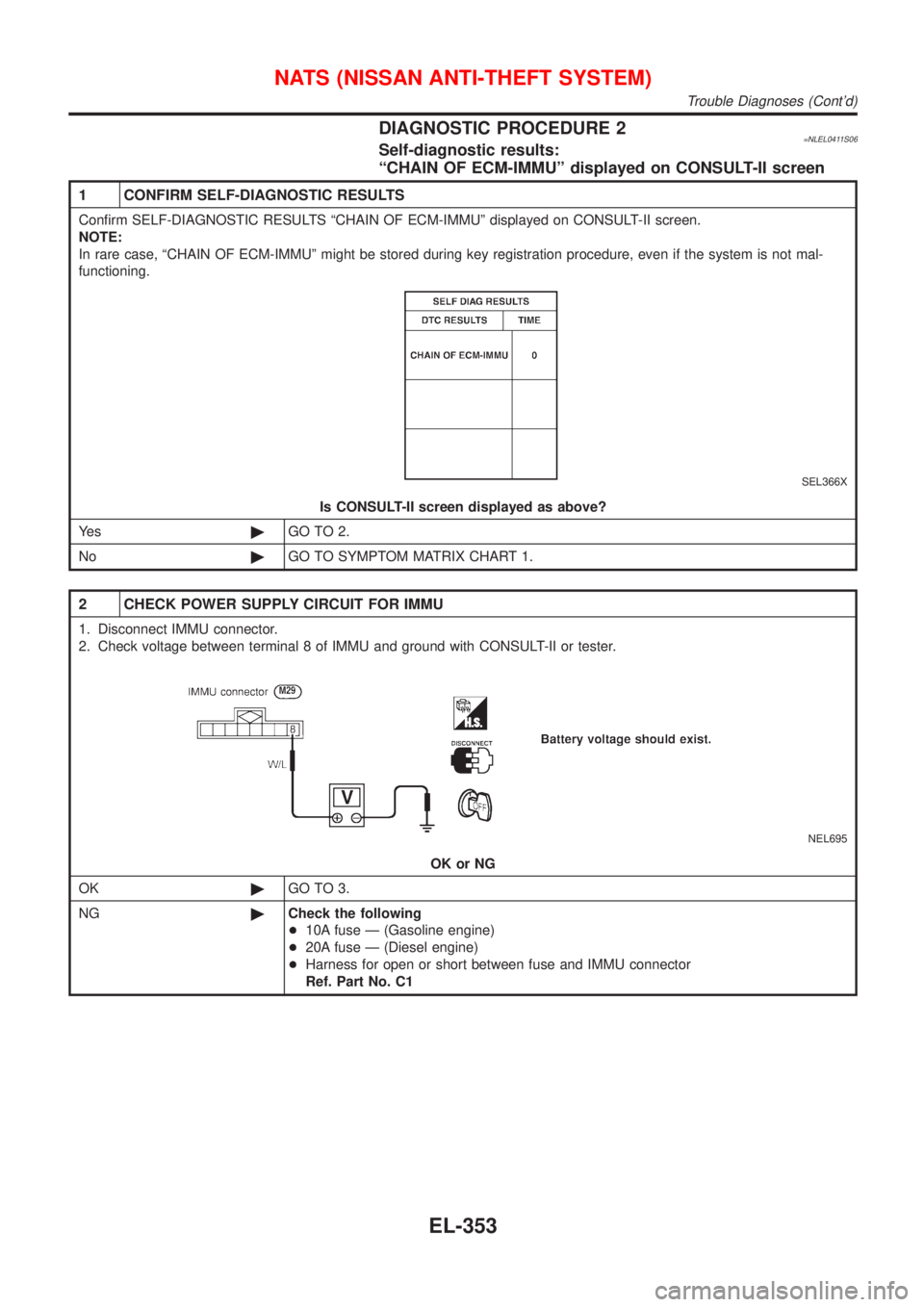
DIAGNOSTIC PROCEDURE 2=NLEL0411S06Self-diagnostic results:
ªCHAIN OF ECM-IMMUº displayed on CONSULT-II screen
1 CONFIRM SELF-DIAGNOSTIC RESULTS
Confirm SELF-DIAGNOSTIC RESULTS ªCHAIN OF ECM-IMMUº displayed on CONSULT-II screen.
NOTE:
In rare case, ªCHAIN OF ECM-IMMUº might be stored during key registration procedure, even if the system is not mal-
functioning.
SEL366X
Is CONSULT-II screen displayed as above?
Ye s©GO TO 2.
No©GO TO SYMPTOM MATRIX CHART 1.
2 CHECK POWER SUPPLY CIRCUIT FOR IMMU
1. Disconnect IMMU connector.
2. Check voltage between terminal 8 of IMMU and ground with CONSULT-II or tester.
NEL695
OK or NG
OK©GO TO 3.
NG©Check the following
+10A fuse Ð (Gasoline engine)
+20A fuse Ð (Diesel engine)
+Harness for open or short between fuse and IMMU connector
Ref. Part No. C1
NATS (NISSAN ANTI-THEFT SYSTEM)
Trouble Diagnoses (Cont'd)
EL-353
Page 2699 of 3051

Engine control component parts
location ................................ EC-26, 560, 1071
Engine control module (ECM) ........ EC-358, 880
Engine control system diagram and
chart .................................... EC-32, 566, 1076
Engine coolant temperature sensor
(ECTS) .............................. EC-169, 694, 1150
Engine fail-safe system .................. EC-123, 647
Engine oil precautions .................................. GI-7
Engine outer component parts ........... EM-12, 82
Engine removal ........................ EM-49, 130, 218
Engine room - See Engine
compartment .......................................... BT-66
Engine serial number ................................. GI-39
Evaporative emission (EVAP)
system ........................................... EC-39, 573
Exhaust gas recirculation (EGR)
valve ........... EC-310, 393, 446, 834, 921, 975
Exhaust system ................................... FE-11, 23
Exterior ...................................................... BT-38
F
F/PUMP - Wiring diagram ............. EC-518, 1034
FR02 - Wiring diagram .. EC-187, 207, 216, 415,
712, 732, 741, 945
FR02/H - Wiring diagram ............... EC-223, 422,
748, 952
FUEL - Wiring diagram ... EC-271, 279, 794, 802
Fan switch ................................................. HA-61
Final drive (FF M/T) ...................... MT-47, 63, 77
Finisher, interior - See Trim ....................... BT-28
Finisher, trunk lid ....................................... BT-31
Floor trim ................................................... BT-28
Fluids ........................................................ MA-20
Flywheel (clutch) ....................................... CL-22
Flywheel runout ........................ EM-60, 142, 235
Fog lamp, front, removal and
installation ................................................ BT-7
Fog lamp, front .......................................... EL-95
Fork rod (M/T) ..................................... MT-26, 64
Freeze frame data .............. EC-61, 71, 585, 596
Front axle .................................................... AX-2
Front bumper ............................................... BT-7
Front combination lamp removal and
installation ................................................ BT-7
Front disc brake ........................................ BR-24
Front door .................................................. BT-13
Front fog lamp removal and
installation ................................................ BT-7
Front fog lamp ........................................... EL-95
Front heated oxygen sensor (HO2S)
heater .......................... EC-221, 421, 746, 951
Front heated oxygen sensor (HO2S) ..... EC-184,
192, 198, 204, 214, 414, 709,
717, 723, 729, 739, 944Front seat belt ............................................. RS-5
Front seat .................................................. BT-46
Front suspension ........................................ SU-2
Front washer ............................................ EL-176
Front wiper ............................................... EL-176
Fuel cut control (at no load & high
engine speed) ..................... EC-39, 573, 1081
Fuel gauge ............................................... EL-130
Fuel injection system ............. EC-269, 277, 792,
800, 1079
Fuel injector .................................. EC-494, 1021
Fuel precautions ........................................... GI-8
Fuel pressure check ......................... EC-43, 577
Fuel pressure regulator .................... EC-44, 578
Fuel pressure release ....................... EC-43, 577
Fuel pump relay ............................ EC-516, 1032
Fuel pump ..................................... EC-516, 1032
Fuel system ........................................... FE-5, 15
Fuel tank vacuum relief valve ........... EC-40, 574
Fuse block ............................................... EL-527
Fuse ........................................................... EL-32
Fusible link ................................................. EL-32G
GLOW - Wiring diagram ....................... EC-1267
Garage jack and safety stand .................... GI-43
Gauges .................................................... EL-130
Gear components (M/T) ..................... MT-25, 63
Generator - See Alternator ....................... SC-28
Generic scan tool (GST) ................... EC-93, 617
Glass .......................................................... BT-14
Glow plug .............................................. EC-1267
Glow relay ............................................. EC-1267
Grease ...................................................... MA-20
Ground distribution .............................. EL-33, 48
H
H/LAMP - Wiring diagram .......................... EL-69
HEATER - Wiring diagram ........................ HA-23
HFC134a (R134a) system
precaution ................................................ HA-2
HFC134a (R134a) system service
procedure .............................................. HA-85
HFC134a (R134a) system service
tools ....................................................... HA-10
HFC134a system service equipment
precaution ................................................ HA-6
HORN - Wiring diagram .......................... EL-193
HSEAT - Wiring diagram ......................... EL-234
Harness connector ...................................... EL-5
Harness layout ......................................... EL-452
Hazard warning lamp .............................. EL-101
Headlamp removal and installation ............. BT-7
Headlamp washer .................................... EL-190
ALPHABETICAL INDEX
IDX-4
Page 2936 of 3051

SRS800
SRS Operation CheckNLRS0047DIAGNOSTIC PROCEDURE 1NLRS0047S01Checking Air Bag Operation by Using“AIR BAG”
Warning Lamp—User Mode
NLRS0047S01011. After turning ignition switch from“OFF”to“ON”,“AIR BAG”
warning lamp operates.
2. Compare“AIR BAG”warning lamp operation to the chart
below.
“AIR BAG”warning lamp operation—User mode—SRS condition Reference item
MRS095A
No malfunction is
detected. No further action
is necessary.
—
MRS096A
The system is malfunction-
ing and needs to be
repaired as indicated.Go to DIAGNOSTIC PRO-
CEDURE 2 or 6 (RS-46 or
RS-55).
MRS097A
Air bag or/and seat belt
pre-tensioner is deployed.Go to COLLISION DIAG-
NOSIS (RS-66).
Air bag fuse, diagnosis
sensor unit or harness is
malfunctioning and needs
to be repaired.Go to DIAGNOSTIC PRO-
CEDURE 9 (RS-63).
MRS098A
One of the following has
occurred and needs to be
repaired.
+Meter fuse is blown.
+“AIR BAG”warning
lamp circuit has open
or short.
+Diagnosis sensor unit is
malfunctioning.Go to DIAGNOSTIC PRO-
CEDURE 10 (RS-65).
NOTE:
If“AIR BAG”warning lamp operates differently from the
operations shown above, refer to“AIR BAG”warning lamp
operation—Diagnosis mode—, DIAGNOSTIC PROCEDURE 6
(step 4), RS-55.
SUPPLEMENTAL RESTRAINT SYSTEM (SRS)
SRS Operation Check
RS-45
Page 2962 of 3051

STARTING & CHARGING SYSTEMS
SECTION
SC
CONTENTS
PRECAUTIONS...............................................................2
Supplemental Restraint System (SRS)″AIR
BAG″and″SEAT BELT PRE-TENSIONER″...............2
Wiring Diagrams and Trouble Diagnoses....................2
BATTERY.........................................................................3
How to Handle Battery ................................................3
METHODS OF PREVENTING OVER-DISCHARGE......3
CHECKING ELECTROLYTE LEVEL............................3
SPECIFIC GRAVITY CHECK......................................4
Battery Test and Charging Chart .................................6
CHART I...................................................................6
CHART II..................................................................7
A: SLOW CHARGE....................................................8
B: STANDARD CHARGE..........................................10
C: QUICK CHARGE................................................. 11
STARTING SYSTEM.....................................................13
System Description ....................................................13
M/T MODELS..........................................................13
A/T MODELS...........................................................13
Wiring Diagram - START -.........................................14
MODELS WITH FUSE AND FUSIBLE LINK BOX
E43
.........................................................................14
MODELS WITH FUSE AND FUSIBLE LINK BOX
E90
.........................................................................15
Trouble Diagnoses.....................................................16
Construction ...............................................................17
Removal and Installation ...........................................19
REMOVAL...............................................................19
INSTALLATION........................................................20
Inspection...................................................................20
MAGNETIC SWITCH CHECK...................................20
PINION/CLUTCH CHECK.........................................20
BRUSH CHECK.......................................................20
YOKE CHECK.........................................................21
ARMATURE CHECK................................................22
Assembly ...................................................................23
PINION PROTRUSION LENGTH ADJUSTMENT........23
CHARGING SYSTEM....................................................24
System Description ....................................................24
Wiring Diagram - CHARGE -.....................................25
MODELS WITH FUSE AND FUSIBLE LINK BOX
E43
.........................................................................25
MODELS WITH FUSE AND FUSIBLE LINK BOX
E90
.........................................................................26
Trouble Diagnoses.....................................................27
WITH IC REGULATOR.............................................27
MALFUNCTION INDICATOR....................................27
Construction ...............................................................28
Removal and Installation ...........................................30
REMOVAL (SR ENGINE)..........................................30
REMOVAL (QG ENGINE).........................................30
REMOVAL (YD ENGINE)..........................................30
INSTALLATION........................................................30
Disassembly...............................................................31
REAR COVER.........................................................31
REAR BEARING......................................................31
Inspection...................................................................31
ROTOR CHECK......................................................31
BRUSH CHECK.......................................................32
STATOR CHECK.....................................................32
Assembly ...................................................................32
RING FITTING IN REAR BEARING...........................32
REAR COVER INSTALLATION.................................33
SERVICE DATA AND SPECIFICATIONS (SDS).........34
Battery........................................................................34
Starter ........................................................................34
Alternator ...................................................................34