engine oil NISSAN ALMERA TINO 2001 Service Service Manual
[x] Cancel search | Manufacturer: NISSAN, Model Year: 2001, Model line: ALMERA TINO, Model: NISSAN ALMERA TINO 2001Pages: 3051, PDF Size: 46.38 MB
Page 900 of 3051
SEF095X
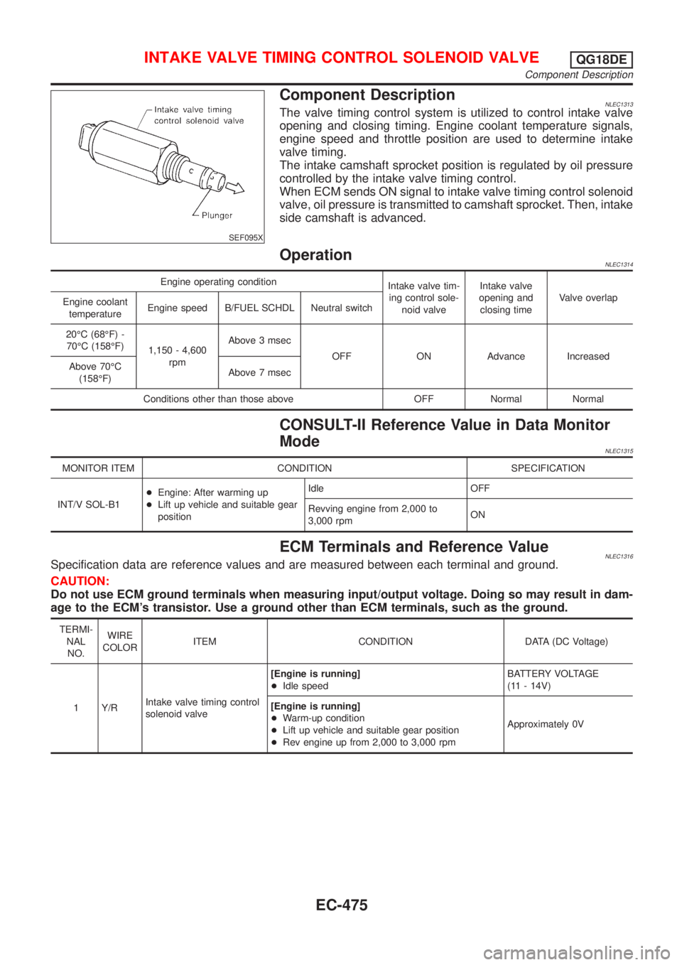
Component DescriptionNLEC1313The valve timing control system is utilized to control intake valve
opening and closing timing. Engine coolant temperature signals,
engine speed and throttle position are used to determine intake
valve timing.
The intake camshaft sprocket position is regulated by oil pressure
controlled by the intake valve timing control.
When ECM sends ON signal to intake valve timing control solenoid
valve, oil pressure is transmitted to camshaft sprocket. Then, intake
side camshaft is advanced.
OperationNLEC1314
Engine operating condition
Intake valve tim-
ing control sole-
noid valveIntake valve
opening and
closing timeValve overlap
Engine coolant
temperatureEngine speed B/FUEL SCHDL Neutral switch
20ÉC (68ÉF) -
70ÉC (158ÉF)
1,150 - 4,600
rpmAbove 3 msec
OFF ON Advance Increased
Above 70ÉC
(158ÉF)Above 7 msec
Conditions other than those above OFF Normal Normal
CONSULT-II Reference Value in Data Monitor
Mode
NLEC1315
MONITOR ITEM CONDITION SPECIFICATION
INT/V SOL-B1+Engine: After warming up
+Lift up vehicle and suitable gear
positionIdle OFF
Revving engine from 2,000 to
3,000 rpmON
ECM Terminals and Reference ValueNLEC1316Specification data are reference values and are measured between each terminal and ground.
CAUTION:
Do not use ECM ground terminals when measuring input/output voltage. Doing so may result in dam-
age to the ECM's transistor. Use a ground other than ECM terminals, such as the ground.
TERMI-
NAL
NO.WIRE
COLORITEM CONDITION DATA (DC Voltage)
1 Y/RIntake valve timing control
solenoid valve[Engine is running]
+Idle speedBATTERY VOLTAGE
(11 - 14V)
[Engine is running]
+Warm-up condition
+Lift up vehicle and suitable gear position
+Rev engine up from 2,000 to 3,000 rpmApproximately 0V
INTAKE VALVE TIMING CONTROL SOLENOID VALVEQG18DE
Component Description
EC-475
Page 919 of 3051
SEF138X
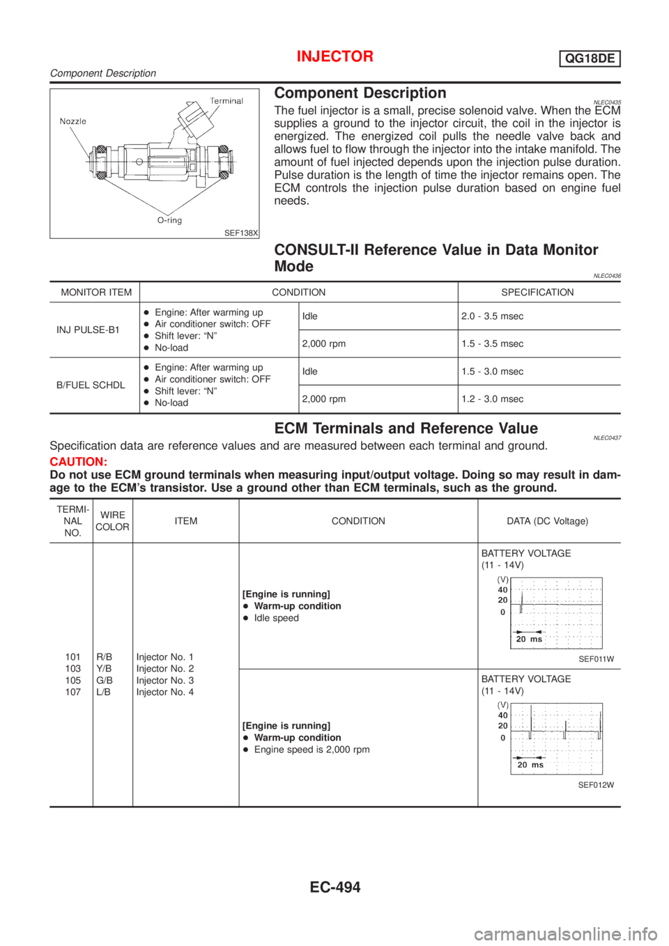
Component DescriptionNLEC0435The fuel injector is a small, precise solenoid valve. When the ECM
supplies a ground to the injector circuit, the coil in the injector is
energized. The energized coil pulls the needle valve back and
allows fuel to flow through the injector into the intake manifold. The
amount of fuel injected depends upon the injection pulse duration.
Pulse duration is the length of time the injector remains open. The
ECM controls the injection pulse duration based on engine fuel
needs.
CONSULT-II Reference Value in Data Monitor
Mode
NLEC0436
MONITOR ITEM CONDITION SPECIFICATION
INJ PULSE-B1+Engine: After warming up
+Air conditioner switch: OFF
+Shift lever: ªNº
+No-loadIdle 2.0 - 3.5 msec
2,000 rpm 1.5 - 3.5 msec
B/FUEL SCHDL+Engine: After warming up
+Air conditioner switch: OFF
+Shift lever: ªNº
+No-loadIdle 1.5 - 3.0 msec
2,000 rpm 1.2 - 3.0 msec
ECM Terminals and Reference ValueNLEC0437Specification data are reference values and are measured between each terminal and ground.
CAUTION:
Do not use ECM ground terminals when measuring input/output voltage. Doing so may result in dam-
age to the ECM's transistor. Use a ground other than ECM terminals, such as the ground.
TERMI-
NAL
NO.WIRE
COLORITEM CONDITION DATA (DC Voltage)
101
103
105
107R/B
Y/B
G/B
L/BInjector No. 1
Injector No. 2
Injector No. 3
Injector No. 4[Engine is running]
+Warm-up condition
+Idle speedBATTERY VOLTAGE
(11 - 14V)
SEF011W
[Engine is running]
+Warm-up condition
+Engine speed is 2,000 rpmBATTERY VOLTAGE
(11 - 14V)
SEF012W
INJECTORQG18DE
Component Description
EC-494
Page 925 of 3051
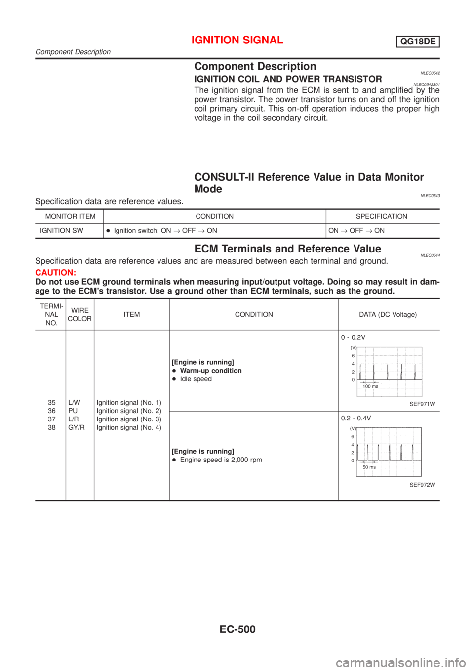
Component DescriptionNLEC0542IGNITION COIL AND POWER TRANSISTORNLEC0542S01The ignition signal from the ECM is sent to and amplified by the
power transistor. The power transistor turns on and off the ignition
coil primary circuit. This on-off operation induces the proper high
voltage in the coil secondary circuit.
CONSULT-II Reference Value in Data Monitor
Mode
NLEC0543Specification data are reference values.
MONITOR ITEM CONDITION SPECIFICATION
IGNITION SW+Ignition switch: ON®OFF®ON ON®OFF®ON
ECM Terminals and Reference ValueNLEC0544Specification data are reference values and are measured between each terminal and ground.
CAUTION:
Do not use ECM ground terminals when measuring input/output voltage. Doing so may result in dam-
age to the ECM's transistor. Use a ground other than ECM terminals, such as the ground.
TERMI-
NAL
NO.WIRE
COLORITEM CONDITION DATA (DC Voltage)
35
36
37
38L/W
PU
L/R
GY/RIgnition signal (No. 1)
Ignition signal (No. 2)
Ignition signal (No. 3)
Ignition signal (No. 4)[Engine is running]
+Warm-up condition
+Idle speed0 - 0.2V
SEF971W
[Engine is running]
+Engine speed is 2,000 rpm0.2 - 0.4V
SEF972W
IGNITION SIGNALQG18DE
Component Description
EC-500
Page 930 of 3051
Diagnostic ProcedureNLEC0579
1 CHECK ENGINE START
Turn ignition switch ªOFFº, and restart engine.
Is engine running?
YesorNo
Yes (With CONSULT-II)©GO TO 2.
Yes (Without CONSULT-
II)©GO TO 12.
No©GO TO 3.
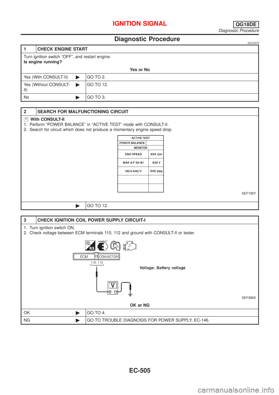
2 SEARCH FOR MALFUNCTIONING CIRCUIT
With CONSULT-II
1. Perform ªPOWER BALANCEº in ªACTIVE TESTº mode with CONSULT-II.
2. Search for circuit which does not produce a momentary engine speed drop.
SEF190Y
©GO TO 12.
3 CHECK IGNITION COIL POWER SUPPLY CIRCUIT-I
1. Turn ignition switch ON.
2. Check voltage between ECM terminals 110, 112 and ground with CONSULT-II or tester.
SEF366X
OK or NG
OK©GO TO 4.
NG©GO TO TROUBLE DIAGNOSIS FOR POWER SUPPLY, EC-146.
IGNITION SIGNALQG18DE
Diagnostic Procedure
EC-505
Page 931 of 3051
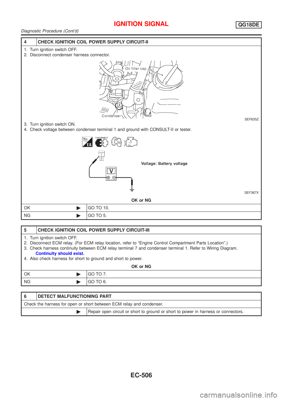
4 CHECK IGNITION COIL POWER SUPPLY CIRCUIT-II
1. Turn ignition switch OFF.
2. Disconnect condenser harness connector.
SEF635Z
3. Turn ignition switch ON.
4. Check voltage between condenser terminal 1 and ground with CONSULT-II or tester.
SEF367X
OK or NG
OK©GO TO 10.
NG©GO TO 5.
5 CHECK IGNITION COIL POWER SUPPLY CIRCUIT-III
1. Turn ignition switch OFF.
2. Disconnect ECM relay. (For ECM relay location, refer to ªEngine Control Compartment Parts Locationº.)
3. Check harness continuity between ECM relay terminal 7 and condenser terminal 1. Refer to Wiring Diagram.
Continuity should exist.
4. Also check harness for short to ground and short to power.
OK or NG
OK©GO TO 7.
NG©GO TO 6.
6 DETECT MALFUNCTIONING PART
Check the harness for open or short between ECM relay and condenser.
©Repair open circuit or short to ground or short to power in harness or connectors.
IGNITION SIGNALQG18DE
Diagnostic Procedure (Cont'd)
EC-506
Page 932 of 3051
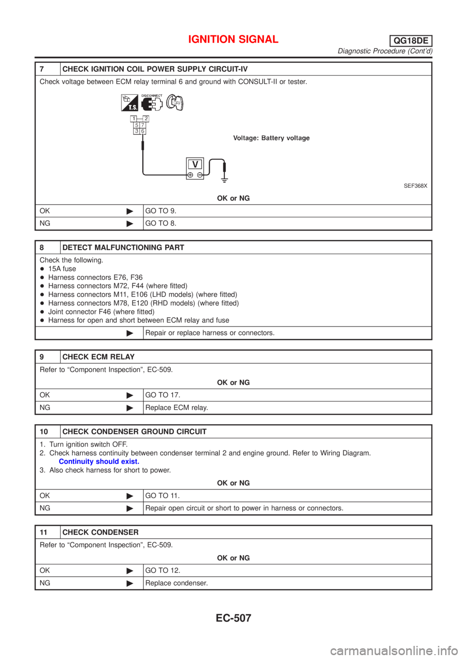
7 CHECK IGNITION COIL POWER SUPPLY CIRCUIT-IV
Check voltage between ECM relay terminal 6 and ground with CONSULT-II or tester.
SEF368X
OK or NG
OK©GO TO 9.
NG©GO TO 8.
8 DETECT MALFUNCTIONING PART
Check the following.
+15A fuse
+Harness connectors E76, F36
+Harness connectors M72, F44 (where fitted)
+Harness connectors M11, E106 (LHD models) (where fitted)
+Harness connectors M78, E120 (RHD models) (where fitted)
+Joint connector F46 (where fitted)
+Harness for open and short between ECM relay and fuse
©Repair or replace harness or connectors.
9 CHECK ECM RELAY
Refer to ªComponent Inspectionº, EC-509.
OK or NG
OK©GO TO 17.
NG©Replace ECM relay.
10 CHECK CONDENSER GROUND CIRCUIT
1. Turn ignition switch OFF.
2. Check harness continuity between condenser terminal 2 and engine ground. Refer to Wiring Diagram.
Continuity should exist.
3. Also check harness for short to power.
OK or NG
OK©GO TO 11.
NG©Repair open circuit or short to power in harness or connectors.
11 CHECK CONDENSER
Refer to ªComponent Inspectionº, EC-509.
OK or NG
OK©GO TO 12.
NG©Replace condenser.
IGNITION SIGNALQG18DE
Diagnostic Procedure (Cont'd)
EC-507
Page 933 of 3051
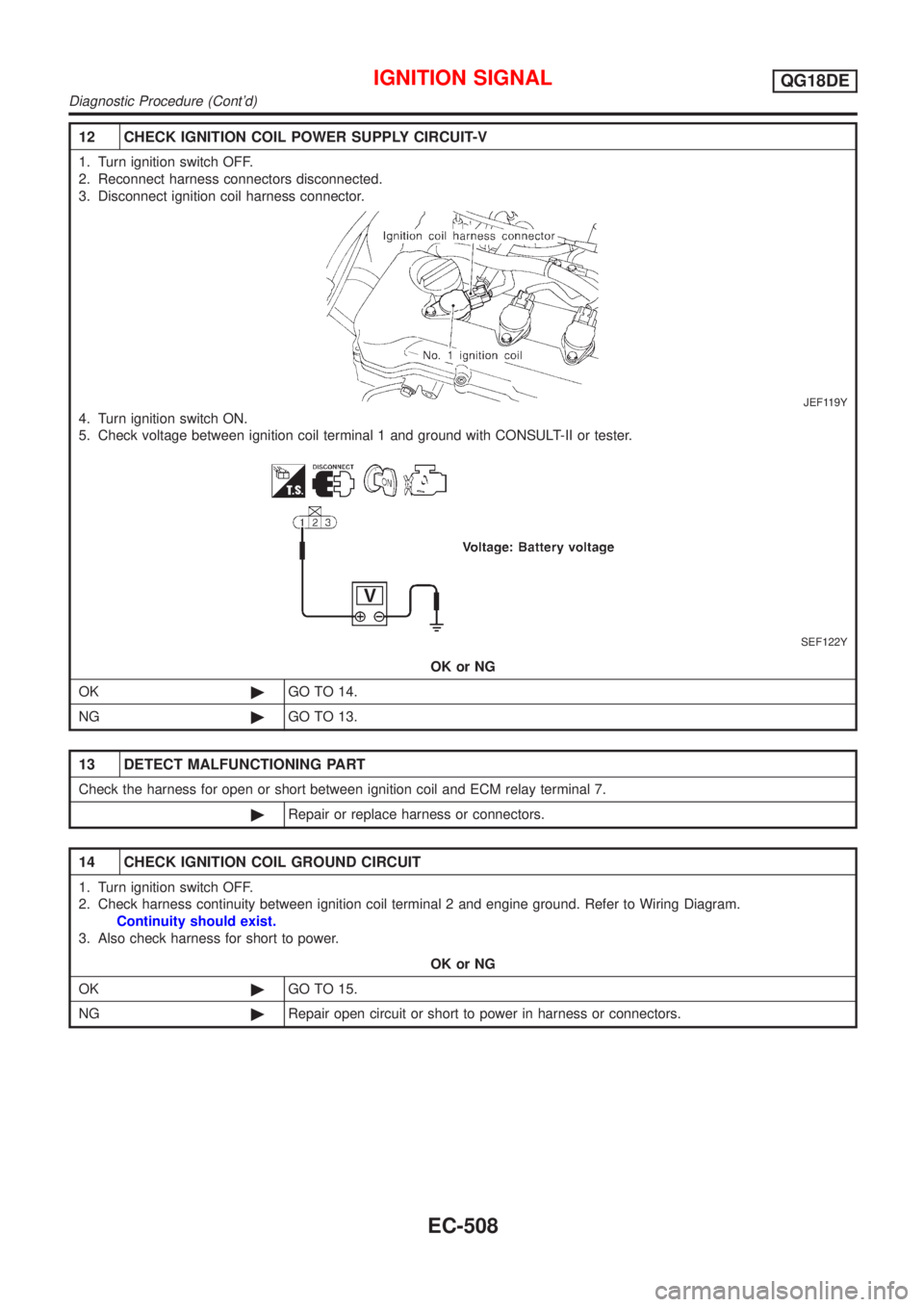
12 CHECK IGNITION COIL POWER SUPPLY CIRCUIT-V
1. Turn ignition switch OFF.
2. Reconnect harness connectors disconnected.
3. Disconnect ignition coil harness connector.
JEF119Y
4. Turn ignition switch ON.
5. Check voltage between ignition coil terminal 1 and ground with CONSULT-II or tester.
SEF122Y
OK or NG
OK©GO TO 14.
NG©GO TO 13.
13 DETECT MALFUNCTIONING PART
Check the harness for open or short between ignition coil and ECM relay terminal 7.
©Repair or replace harness or connectors.
14 CHECK IGNITION COIL GROUND CIRCUIT
1. Turn ignition switch OFF.
2. Check harness continuity between ignition coil terminal 2 and engine ground. Refer to Wiring Diagram.
Continuity should exist.
3. Also check harness for short to power.
OK or NG
OK©GO TO 15.
NG©Repair open circuit or short to power in harness or connectors.
IGNITION SIGNALQG18DE
Diagnostic Procedure (Cont'd)
EC-508
Page 948 of 3051
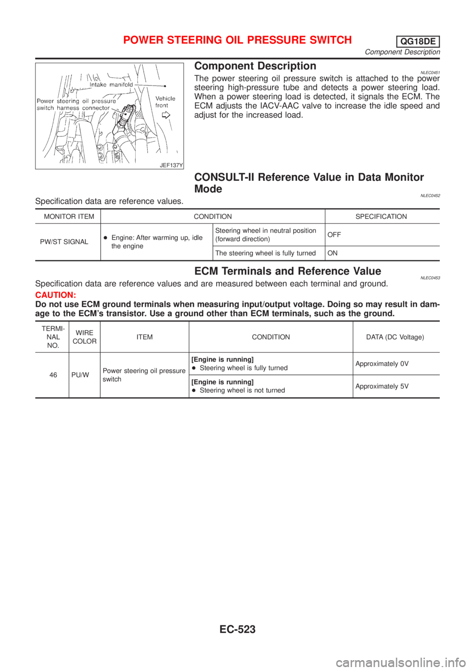
JEF137Y
Component DescriptionNLEC0451The power steering oil pressure switch is attached to the power
steering high-pressure tube and detects a power steering load.
When a power steering load is detected, it signals the ECM. The
ECM adjusts the IACV-AAC valve to increase the idle speed and
adjust for the increased load.
CONSULT-II Reference Value in Data Monitor
Mode
NLEC0452Specification data are reference values.
MONITOR ITEM CONDITION SPECIFICATION
PW/ST SIGNAL+Engine: After warming up, idle
the engineSteering wheel in neutral position
(forward direction)OFF
The steering wheel is fully turned ON
ECM Terminals and Reference ValueNLEC0453Specification data are reference values and are measured between each terminal and ground.
CAUTION:
Do not use ECM ground terminals when measuring input/output voltage. Doing so may result in dam-
age to the ECM's transistor. Use a ground other than ECM terminals, such as the ground.
TERMI-
NAL
NO.WIRE
COLORITEM CONDITION DATA (DC Voltage)
46 PU/WPower steering oil pressure
switch[Engine is running]
+Steering wheel is fully turnedApproximately 0V
[Engine is running]
+Steering wheel is not turnedApproximately 5V
POWER STEERING OIL PRESSURE SWITCHQG18DE
Component Description
EC-523
Page 949 of 3051
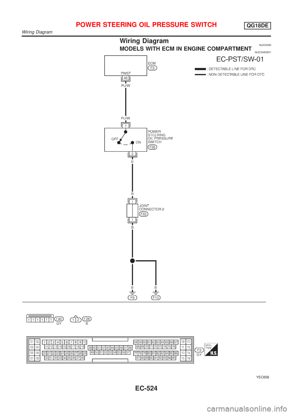
Wiring DiagramNLEC0450MODELS WITH ECM IN ENGINE COMPARTMENTNLEC0450S01
YEC658
POWER STEERING OIL PRESSURE SWITCHQG18DE
Wiring Diagram
EC-524
Page 951 of 3051
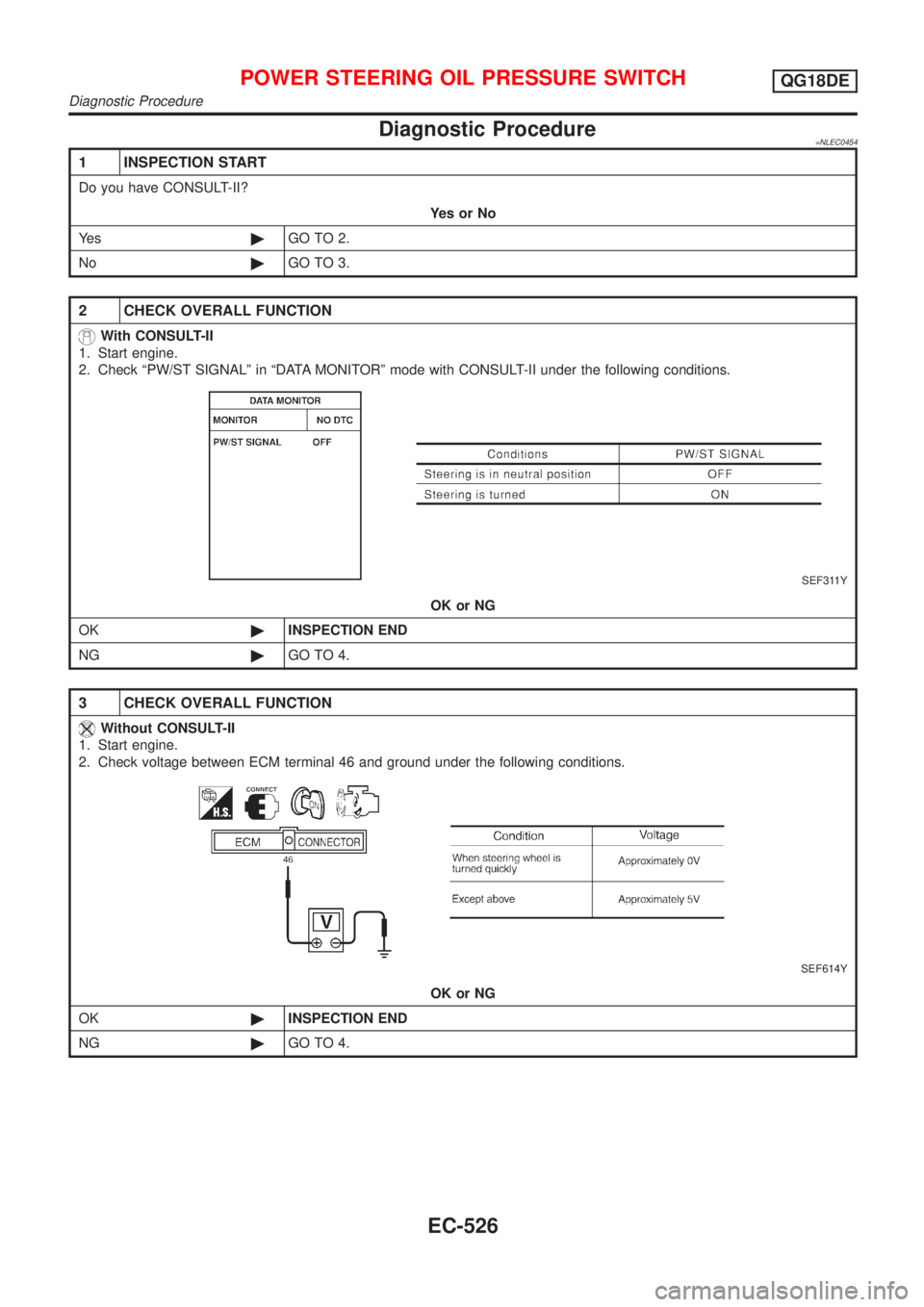
Diagnostic Procedure=NLEC0454
1 INSPECTION START
Do you have CONSULT-II?
YesorNo
Ye s©GO TO 2.
No©GO TO 3.
2 CHECK OVERALL FUNCTION
With CONSULT-II
1. Start engine.
2. Check ªPW/ST SIGNALº in ªDATA MONITORº mode with CONSULT-II under the following conditions.
SEF311Y
OK or NG
OK©INSPECTION END
NG©GO TO 4.
3 CHECK OVERALL FUNCTION
Without CONSULT-II
1. Start engine.
2. Check voltage between ECM terminal 46 and ground under the following conditions.
SEF614Y
OK or NG
OK©INSPECTION END
NG©GO TO 4.
POWER STEERING OIL PRESSURE SWITCHQG18DE
Diagnostic Procedure
EC-526