wiring diagram NISSAN ALMERA TINO 2001 Service Repair Manual
[x] Cancel search | Manufacturer: NISSAN, Model Year: 2001, Model line: ALMERA TINO, Model: NISSAN ALMERA TINO 2001Pages: 3051, PDF Size: 46.38 MB
Page 2626 of 3051

YHA350
TROUBLE DIAGNOSES
Wiring Diagram—A/C, M—(Cont’d)
HA-35
Page 2627 of 3051

YHA351
TROUBLE DIAGNOSES
Wiring Diagram—A/C, M—(Cont’d)
HA-36
Page 2628 of 3051

Models with Diesel EngineNLHA0128S0402
YHA352
TROUBLE DIAGNOSES
Wiring Diagram—A/C, M—(Cont’d)
HA-37
Page 2629 of 3051

YHA353
TROUBLE DIAGNOSES
Wiring Diagram—A/C, M—(Cont’d)
HA-38
Page 2630 of 3051

YHA354
TROUBLE DIAGNOSES
Wiring Diagram—A/C, M—(Cont’d)
HA-39
Page 2635 of 3051

NHA463
COMPONENT DESCRIPTIONNLHA0209Intake Door MotorNLHA0209S01The intake door motor is attached to the intake unit. It rotates so
that air is drawn from inlets set by the heater control panel. Motor
rotation is conveyed to a lever which activates the intake door.
DIAGNOSTIC PROCEDURE FOR INTAKE DOOR
MOTOR CIRCUIT
NLHA0210
1 CHECK POWER SUPPLY FOR HEATER CONTROL PANEL
Do approx. 12 volts exist between heater control panel harness terminal No. 1 and body ground?
NHA462
YesorNo
Ye s©GO TO 2.
No©Check 10A (No. 15) fuse at fuse block. Refer to EL-10,“Wiring Diagram—POWER—”.
2 CHECK RECIRCULATION (REC) SWITCH
Refer to HA-46.
OK or NG
OK©GO TO 3.
NG©Replace recirculation (REC) switch.
TROUBLE DIAGNOSES
Intake Door (Cont’d)
HA-44
Page 2647 of 3051
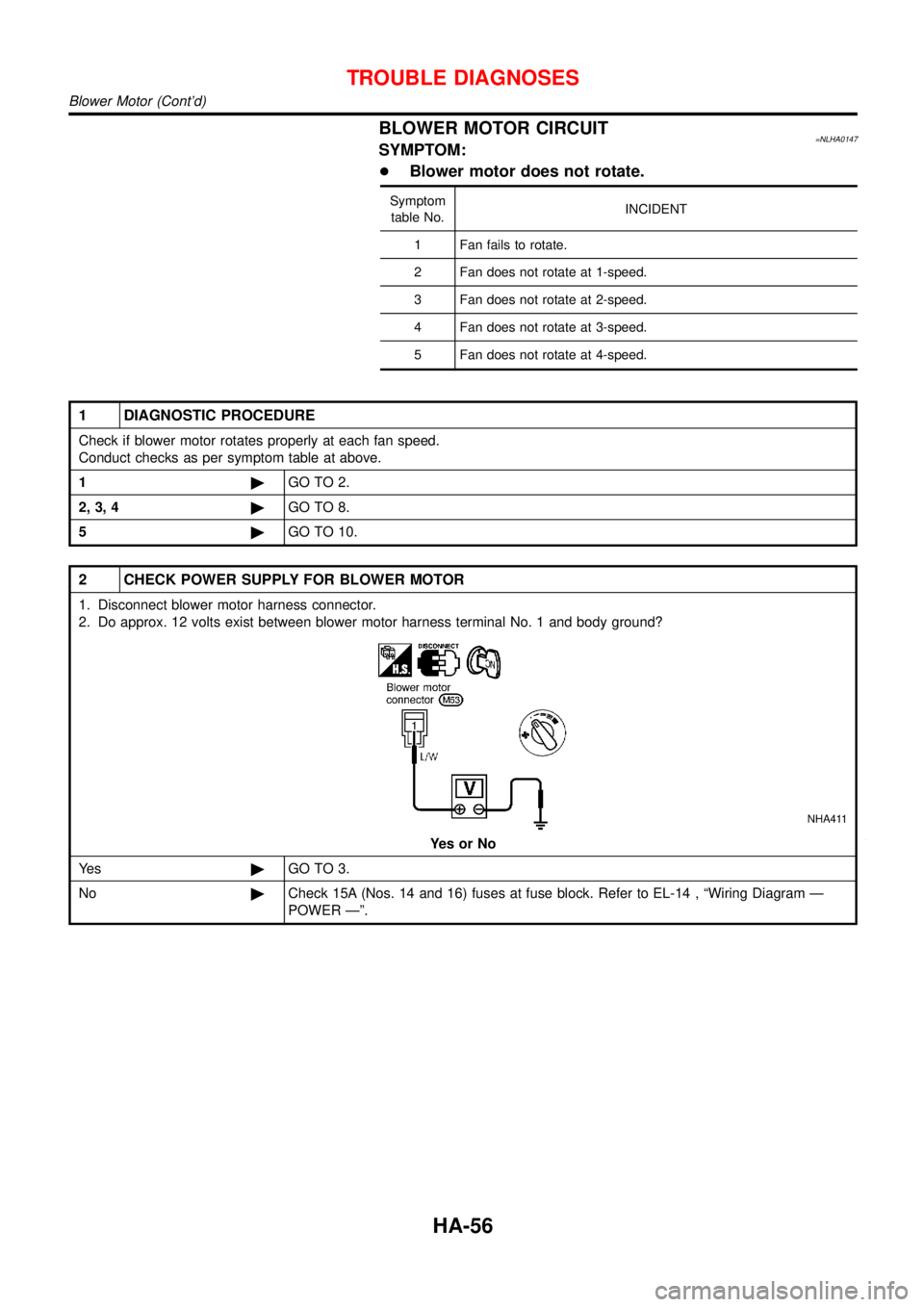
BLOWER MOTOR CIRCUIT=NLHA0147SYMPTOM:
+Blower motor does not rotate.
Symptom
table No.INCIDENT
1 Fan fails to rotate.
2 Fan does not rotate at 1-speed.
3 Fan does not rotate at 2-speed.
4 Fan does not rotate at 3-speed.
5 Fan does not rotate at 4-speed.
1 DIAGNOSTIC PROCEDURE
Check if blower motor rotates properly at each fan speed.
Conduct checks as per symptom table at above.
1©GO TO 2.
2, 3, 4©GO TO 8.
5©GO TO 10.
2 CHECK POWER SUPPLY FOR BLOWER MOTOR
1. Disconnect blower motor harness connector.
2. Do approx. 12 volts exist between blower motor harness terminal No. 1 and body ground?
NHA411
YesorNo
Ye s©GO TO 3.
No©Check 15A (Nos. 14 and 16) fuses at fuse block. Refer to EL-14 ,“Wiring Diagram—
POWER—”.
TROUBLE DIAGNOSES
Blower Motor (Cont’d)
HA-56
Page 2655 of 3051

4 CHECK POWER SUPPLY FOR A/C RELAY
Disconnect A/C relay.
Do approx. 12 volts exist between A/C relay harness terminal Nos. 1, 5 and body ground?
RHA635H
YesorNo
Ye s©GO TO 5.
No©Check power supply circuit and 10A (No. 15) fuse at fuse block. Refer to EL-10,“Wiring
Diagram—POWER—”.
5 CHECK A/C RELAY AFTER DISCONNECTING IT
Refer to HA-73.
OK or NG
OK©Reconnect A/C relay. GO TO 6.
NG©Replace A/C relay.
6 CHECK COIL SIDE CIRCUIT OF A/C RELAY
Do approx. 12 volts exist between ECM harness terminal No. 23 and body ground?
NHA421
YesorNo
Ye s©GO TO 8.
No©Disconnect A/C relay. Disconnect ECM harness connector. GO TO 7.
TROUBLE DIAGNOSES
Magnet Clutch (Cont’d)
HA-64
Page 2661 of 3051

4 CHECK POWER SUPPLY FOR A/C RELAY
Disconnect A/C relay.
Do approx. 12 volts exist between A/C relay harness terminal Nos. 1, 5 and body ground?
RHA635H
YesorNo
Ye s©GO TO 5.
No©Check power supply circuit and 10A (No. 15) fuse at fuse block. Refer to EL-10,“Wiring
Diagram—POWER—”.
5 CHECK A/C RELAY AFTER DISCONNECTING IT
Refer to HA-73.
OK or NG
OK©Reconnect A/C relay. GO TO 6.
NG©Replace A/C relay.
6 CHECK COIL SIDE CIRCUIT OF A/C RELAY
Do approx. 12 volts exist between ECM harness terminal No. 204 and body ground?
NHA429
YesorNo
Ye s©GO TO 8.
No©Disconnect A/C relay. Disconnect ECM harness connector. GO TO 7.
TROUBLE DIAGNOSES
Magnet Clutch (Cont’d)
HA-70
Page 2697 of 3051

A
A/C HFC134a (R134a) system precaution . HA-2
A/C HFC134a (R134a) system service
procedure .............................................. HA-85
A/C HFC134a (R134a) system service
tools ....................................................... HA-10
A/C HFC134a system service equip-
ment precaution ....................................... HA-6
A/C air flow ............................................... HA-19
A/C component layout .............................. HA-17
A/C compressor clutch removal and
installation .............................................. HA-90
A/C compressor precaution ........................ HA-5
A/C compressor special service tool .......... HA-9
A/C control linkage adjustment
(manual A/C) ......................................... HA-48
A/C control operation (manual A/C) .......... HA-18
A/C diagnostic work flow (manual
A/C) ...................................................... HA-40
A/C harness layout (manual A/C) ............. HA-21
A/C lubricant (R134a) ............................... HA-87
A/C operational check ............................... HA-41
A/C performance chart .............................. HA-78
A/C performance test diagnoses .............. HA-76
A/C relay ................................................... HA-73
A/C service data specification ................ HA-104
A/C switch ................................................. HA-74
A/C, M - Wiring diagram ........................... HA-27
A/CCUT - Wiring diagram ..................... EC-1301
A/T - Wiring diagram - AT - BA/FTS ........ AT-172
A/T - Wiring diagram - AT - ENG SS ........ AT-91,
177
A/T - Wiring diagram - AT - FTS ................ AT-75
A/T - Wiring diagram - AT - LPSV ... AT-101, 159
A/T - Wiring diagram - AT - MAIN ............. AT-62
A/T - Wiring diagram - AT - PNP/SW ........ AT-68
A/T - Wiring diagram - AT - SSV/A .......... AT-147
A/T - Wiring diagram - AT - TCV ....... AT-96, 166
A/T - Wiring diagram - AT - TPS ..... AT-106, 139
A/T - Wiring diagram - AT - VSS/AT .. AT-86, 128
A/T - Wiring diagram - AT -
VSSMTR .............................................. AT-134
A/T control ............................................. EC-1012
A/T diagnosis communication line .......... EC-928
A/T shift lock system - Wiring
diagram ................................................ AT-196
A/T shift lock system ................................ AT-195
A/T trouble diagnoses .......................... AT-41, 46
AAC/V - Wiring diagram . EC-345, 468, 865, 997
ABS (anti-lock brake system) ................... BR-42
ABS - Wiring diagram ............................... BR-48
ABS sensor rotor ....................................... AX-23
APS - Wiring diagram ........................... EC-1155
AT/C - Wiring diagram .......................... EC-1013
ATDIAG - Wiring diagram ....................... EC-929
Accelerator control system .................... FE-3, 14
Accelerator position sensor ................... EC-1155
Air bag disposal ........................................ RS-30Air bag precautions .................................. GI-3
Air bag ....................................................... RS-16
Air bleeding (hydraulic clutch) ................... CL-10
Air bleeding for brake system ..................... BR-8
Air conditioner cut control ....... EC-38, 572, 1081
Air flow meter - See Mass air flow
sensor ................................ EC-154, 679, 1143
Air mix door control linkage
adjustment ............................................. HA-50
Air spoiler, rear .......................................... BT-38
Alternator ................................................... SC-28
Angular tightening application ...... EM-5, 76, 158
Antenna - See Power antenna ................ EL-233
Anti-lock brake system - Wiring
diagram .................................................. BR-48
Audio and A/C control removal and
installation - See Instrument panel ........ BT-22
Audio ........................................................ EL-208
Automatic transaxle number ...................... GI-40
Auxiliary air control (AAC) valve .... EC-343, 466,
863, 995
B
Back-up lamp switch (M/T) ....................... MT-16
Back-up lamp ............................................. EL-93
Ball joint (front) .......................................... SU-13
Basic inspection ...................... EC-99, 623,1111
Battery ......................................................... SC-3
Baulk ring (M/T) .................................. MT-25, 63
Blower motor ............................................. HA-61
Blower resistor .......................................... HA-61
Board-on lift ................................................ GI-42
Body alignment .......................................... BT-65
Brake booster ............................................ BR-16
Brake fluid change ...................................... BR-7
Brake fluid level and line check .................. BR-7
Brake hydraulic line .................................... BR-9
Brake pedal ............................................... BR-11
Bulb specifications ................................... EL-524
Bumper, front .............................................. BT-7
Bumper, rear .............................................. BT-10
C
CHARGE - Wiring diagram ....................... SC-25
CHIME - Wiring diagram ......................... EL-166
CIGAR - Wiring diagram ......................... EL-195
CKPS - Wiring diagram . EC-297, 440, 821, 911,
970, 1166
CMPS - Wiring diagram .................. EC-304, 828
CONSULT for ABS .................................... BR-58
CONSULT for engine .............. EC-82, 607, 1102
COOL/F - Wiring diagram ..... EC-376, 885, 1201
Camshaft inspection ................. EM-36, 114, 204
Camshaft position sensor (CMPS) . EC-302, 825
Camshaft position sensor (PHASE) ........ EC-302
ALPHABETICAL INDEX
IDX-2