check engine NISSAN ALMERA TINO 2001 Service Repair Manual
[x] Cancel search | Manufacturer: NISSAN, Model Year: 2001, Model line: ALMERA TINO, Model: NISSAN ALMERA TINO 2001Pages: 3051, PDF Size: 46.38 MB
Page 2 of 3051
AUTOMATIC TRANSAXLE
SECTION
AT
CONTENTS
EURO-OBD
TROUBLE DIAGNOSIS - INDEX....................................4
Alphabetical & P No. Index for DTC ...........................4
PRECAUTIONS...............................................................6
Precautions for Supplemental Restraint System
(SRS)²AIR BAG²and²SEAT BELT
PRE-TENSIONER²......................................................6
Precautions for On Board Diagnostic (EURO-
OBD) System of CVT and Engine...............................6
Precautions ..................................................................6
Service Notice or Precautions .....................................7
Wiring Diagrams and Trouble Diagnoses....................8
PREPARATION...............................................................9
Special Service Tools ..................................................9
CVT FLUID.....................................................................10
Checking CVT Fluid...................................................10
Changing CVT Fluid .................................................. 11
OVERALL SYSTEM......................................................12
CVT Electrical Parts Location....................................12
Circuit Diagram ..........................................................13
Cross-sectional View - RE0F06A ..............................14
Control System ..........................................................15
EURO-OBD
ON BOARD DIAGNOSTIC SYSTEM
DESCRIPTION...............................................................18
Introduction ................................................................18
EURO-OBD Function for CVT System......................18
EURO-OBD Diagnostic Trouble Code (DTC)............18
Malfunction Indicator (MI) ..........................................21
CONSULT-II ...............................................................21
EXCEPT FOR EURO-OBD
ON BOARD DIAGNOSTIC SYSTEM
DESCRIPTION...............................................................31CONSULT-II ...............................................................31
Diagnostic Procedure Without CONSULT-II ..............35
EURO-OBD
TROUBLE DIAGNOSIS - INTRODUCTION..................41
Introduction ................................................................41
Work Flow ..................................................................44
EXCEPT FOR EURO-OBD
TROUBLE DIAGNOSIS - INTRODUCTION..................46
Introduction ................................................................46
Work Flow ..................................................................49
TROUBLE DIAGNOSIS - BASIC INSPECTION...........51
CVT Fluid Check .......................................................51
Stall Test ....................................................................51
Line Pressure Test .....................................................52
Road Test...................................................................53
TROUBLE DIAGNOSIS - GENERAL
DESCRIPTION...............................................................58
TCM Terminals and Reference Value........................58
TROUBLE DIAGNOSIS FOR POWER SUPPLY..........62
Wiring Diagram - AT - MAIN ......................................62
TCM Terminals and Reference Value........................64
Diagnostic Procedure ................................................65
EURO-OBD
DTC P0705 PARK/NEUTRAL POSITION (PNP)
SWITCH.........................................................................66
Description .................................................................66
Wiring Diagram - AT - PNP/SW.................................68
Diagnostic Procedure ................................................70
Component Inspection ...............................................72
DTC P0710 CVT FLUID TEMPERATURE SENSOR
CIRCUIT.........................................................................73
Description .................................................................73
Page 11 of 3051
SMA146B
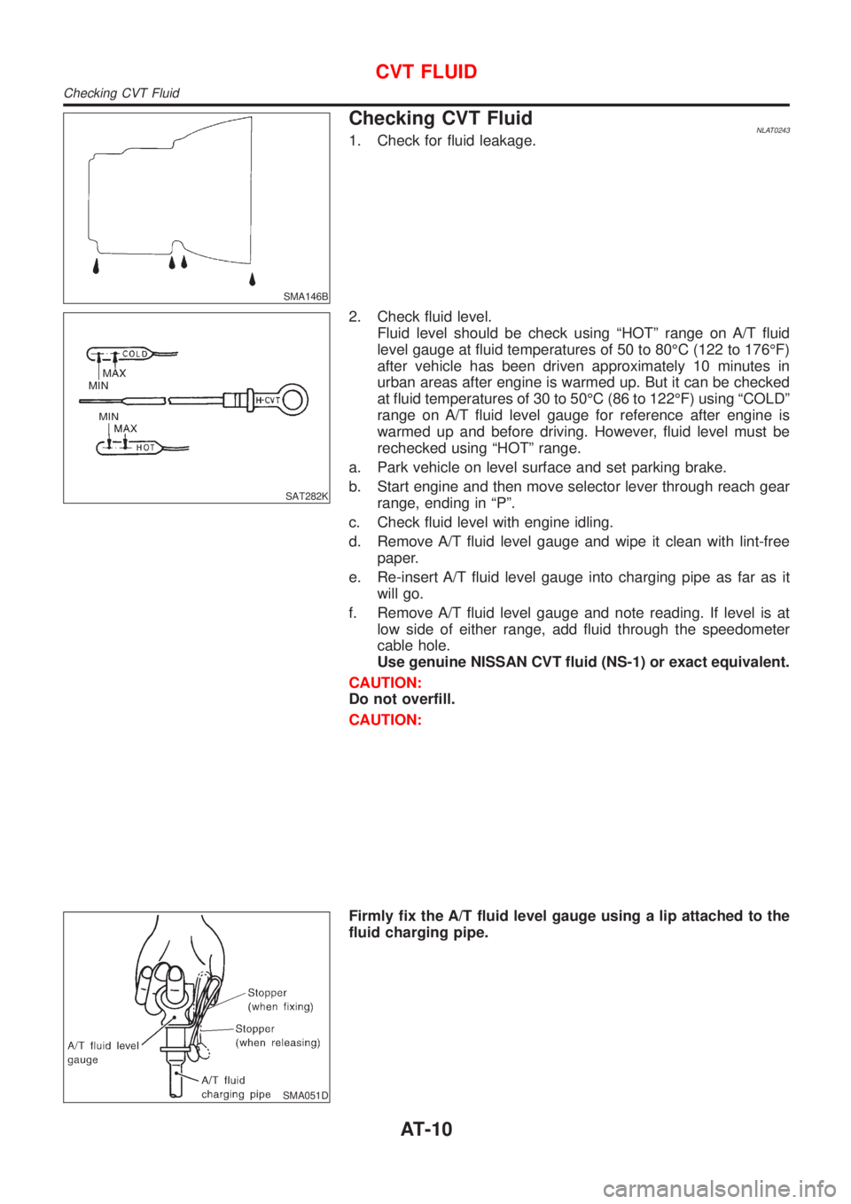
Checking CVT FluidNLAT02431. Check for fluid leakage.
SAT282K
2. Check fluid level.
Fluid level should be check using ªHOTº range on A/T fluid
level gauge at fluid temperatures of 50 to 80ÉC (122 to 176ÉF)
after vehicle has been driven approximately 10 minutes in
urban areas after engine is warmed up. But it can be checked
at fluid temperatures of 30 to 50ÉC (86 to 122ÉF) using ªCOLDº
range on A/T fluid level gauge for reference after engine is
warmed up and before driving. However, fluid level must be
rechecked using ªHOTº range.
a. Park vehicle on level surface and set parking brake.
b. Start engine and then move selector lever through reach gear
range, ending in ªPº.
c. Check fluid level with engine idling.
d. Remove A/T fluid level gauge and wipe it clean with lint-free
paper.
e. Re-insert A/T fluid level gauge into charging pipe as far as it
will go.
f. Remove A/T fluid level gauge and note reading. If level is at
low side of either range, add fluid through the speedometer
cable hole.
Use genuine NISSAN CVT fluid (NS-1) or exact equivalent.
CAUTION:
Do not overfill.
CAUTION:
SMA051D
Firmly fix the A/T fluid level gauge using a lip attached to the
fluid charging pipe.
CVT FLUID
Checking CVT Fluid
AT-10
Page 12 of 3051
SMA853B
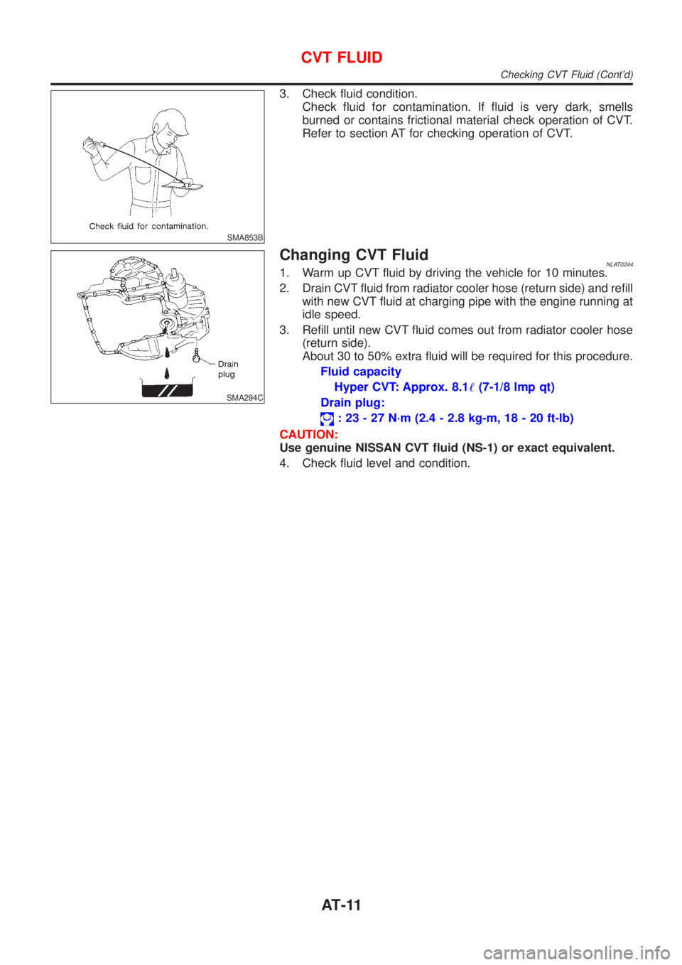
3. Check fluid condition.
Check fluid for contamination. If fluid is very dark, smells
burned or contains frictional material check operation of CVT.
Refer to section AT for checking operation of CVT.
SMA294C
Changing CVT FluidNLAT02441. Warm up CVT fluid by driving the vehicle for 10 minutes.
2. Drain CVT fluid from radiator cooler hose (return side) and refill
with new CVT fluid at charging pipe with the engine running at
idle speed.
3. Refill until new CVT fluid comes out from radiator cooler hose
(return side).
About 30 to 50% extra fluid will be required for this procedure.
Fluid capacity
Hyper CVT: Approx. 8.1!(7-1/8 lmp qt)
Drain plug:
: 23 - 27 N´m (2.4 - 2.8 kg-m, 18 - 20 ft-lb)
CAUTION:
Use genuine NISSAN CVT fluid (NS-1) or exact equivalent.
4. Check fluid level and condition.
CVT FLUID
Checking CVT Fluid (Cont'd)
AT-11
Page 22 of 3051
HOW TO ERASE DTC (WITH GST)=NLAT0020S041. If the ignition switch stays ªONº after repair work, be sure to turn ignition switch ªOFFº once. Wait at least
5 seconds and then turn it ªONº (engine stopped) again.
2. Perform ªEURO-OBD SELF-DIAGNOSTIC PROCEDURE (No Tools)º. Refer to AT-28. (The engine
warm-up step can be skipped when performing the diagnosis only to erase the DTC.)
3. Select Mode 4 with Generic Scan Tool (GST). For details, refer to EC section ªGeneric Scan Tool (GST)º.
HOW TO ERASE DTC (NO TOOLS)NLAT0020S051. If the ignition switch stays ªONº after repair work, be sure to turn ignition switch ªOFFº once. Wait at least
5 seconds and then turn it ªONº (engine stopped) again.
2. Perform ªTCM SELF-DIAGNOSTIC PROCEDURE (No Tools)º. Refer to AT-28. (The engine warm-up step
can be skipped when performing the diagnosis only to erase the DTC.)
3. Change the diagnostic test mode from Mode II to Mode I by turning the mode selector on the ECM.
Refer to EC section ªHOW TO SWITCH DIAGNOSTIC TEST MODESº.
SAT652J
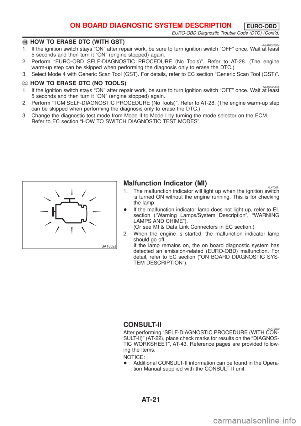
Malfunction Indicator (MI)NLAT00211. The malfunction indicator will light up when the ignition switch
is turned ON without the engine running. This is for checking
the lamp.
+If the malfunction indicator lamp does not light up, refer to EL
section (ªWarning Lamps/System Descriptionº, ªWARNING
LAMPS AND CHIMEº).
(Or see MI & Data Link Connectors in EC section.)
2. When the engine is started, the malfunction indicator lamp
should go off.
If the lamp remains on, the on board diagnostic system has
detected an emission-related (EURO-OBD) malfunction. For
detail, refer to EC section (ªON BOARD DIAGNOSTIC SYS-
TEM DESCRIPTIONº).
CONSULT-IINLAT0022After performing ªSELF-DIAGNOSTIC PROCEDURE (WITH CON-
SULT-II)º (AT-22), place check marks for results on the ªDIAGNOS-
TIC WORKSHEETº, AT-43. Reference pages are provided follow-
ing the items.
NOTICE:
+Additional CONSULT-II information can be found in the Opera-
tion Manual supplied with the CONSULT-II unit.
ON BOARD DIAGNOSTIC SYSTEM DESCRIPTIONEURO-OBD
EURO-OBD Diagnostic Trouble Code (DTC) (Cont'd)
AT-21
Page 23 of 3051
SAT250K
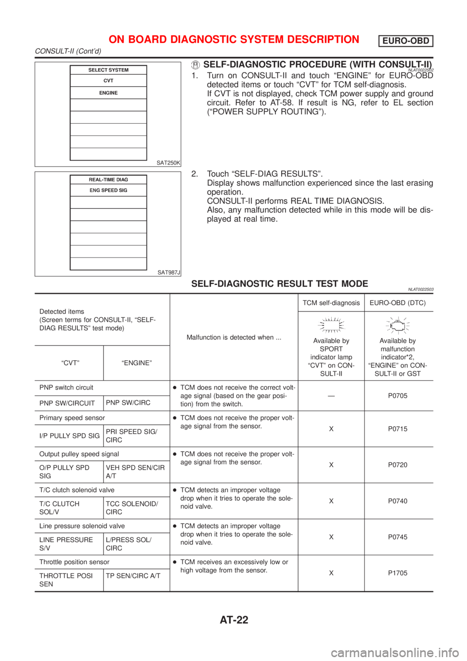
SELF-DIAGNOSTIC PROCEDURE (WITH CONSULT-II)NLAT0022S021. Turn on CONSULT-II and touch ªENGINEº for EURO-OBD
detected items or touch ªCVTº for TCM self-diagnosis.
If CVT is not displayed, check TCM power supply and ground
circuit. Refer to AT-58. If result is NG, refer to EL section
(ªPOWER SUPPLY ROUTINGº).
SAT987J
2. Touch ªSELF-DIAG RESULTSº.
Display shows malfunction experienced since the last erasing
operation.
CONSULT-II performs REAL TIME DIAGNOSIS.
Also, any malfunction detected while in this mode will be dis-
played at real time.
SELF-DIAGNOSTIC RESULT TEST MODENLAT0022S03
Detected items
(Screen terms for CONSULT-II, ªSELF-
DIAG RESULTSº test mode)
Malfunction is detected when ...TCM self-diagnosis EURO-OBD (DTC)
Available by
SPORT
indicator lamp
ªCVTº on CON-
SULT-IIAvailable by
malfunction
indicator*2,
ªENGINEº on CON-
SULT-II or GST ªCVTº ªENGINEº
PNP switch circuit+TCM does not receive the correct volt-
age signal (based on the gear posi-
tion) from the switch.Ð P0705
PNP SW/CIRCUITPNP SW/CIRC
Primary speed sensor+TCM does not receive the proper volt-
age signal from the sensor.
X P0715
I/P PULLY SPD SIGPRI SPEED SIG/
CIRC
Output pulley speed signal+TCM does not receive the proper volt-
age signal from the sensor.
X P0720
O/P PULLY SPD
SIGVEH SPD SEN/CIR
A/T
T/C clutch solenoid valve+TCM detects an improper voltage
drop when it tries to operate the sole-
noid valve.X P0740
T/C CLUTCH
SOL/VTCC SOLENOID/
CIRC
Line pressure solenoid valve+TCM detects an improper voltage
drop when it tries to operate the sole-
noid valve.X P0745
LINE PRESSURE
S/VL/PRESS SOL/
CIRC
Throttle position sensor+TCM receives an excessively low or
high voltage from the sensor.
X P1705
THROTTLE POSI
SENTP SEN/CIRC A/T
ON BOARD DIAGNOSTIC SYSTEM DESCRIPTIONEURO-OBD
CONSULT-II (Cont'd)
AT-22
Page 29 of 3051
SAT491J
SAT234K
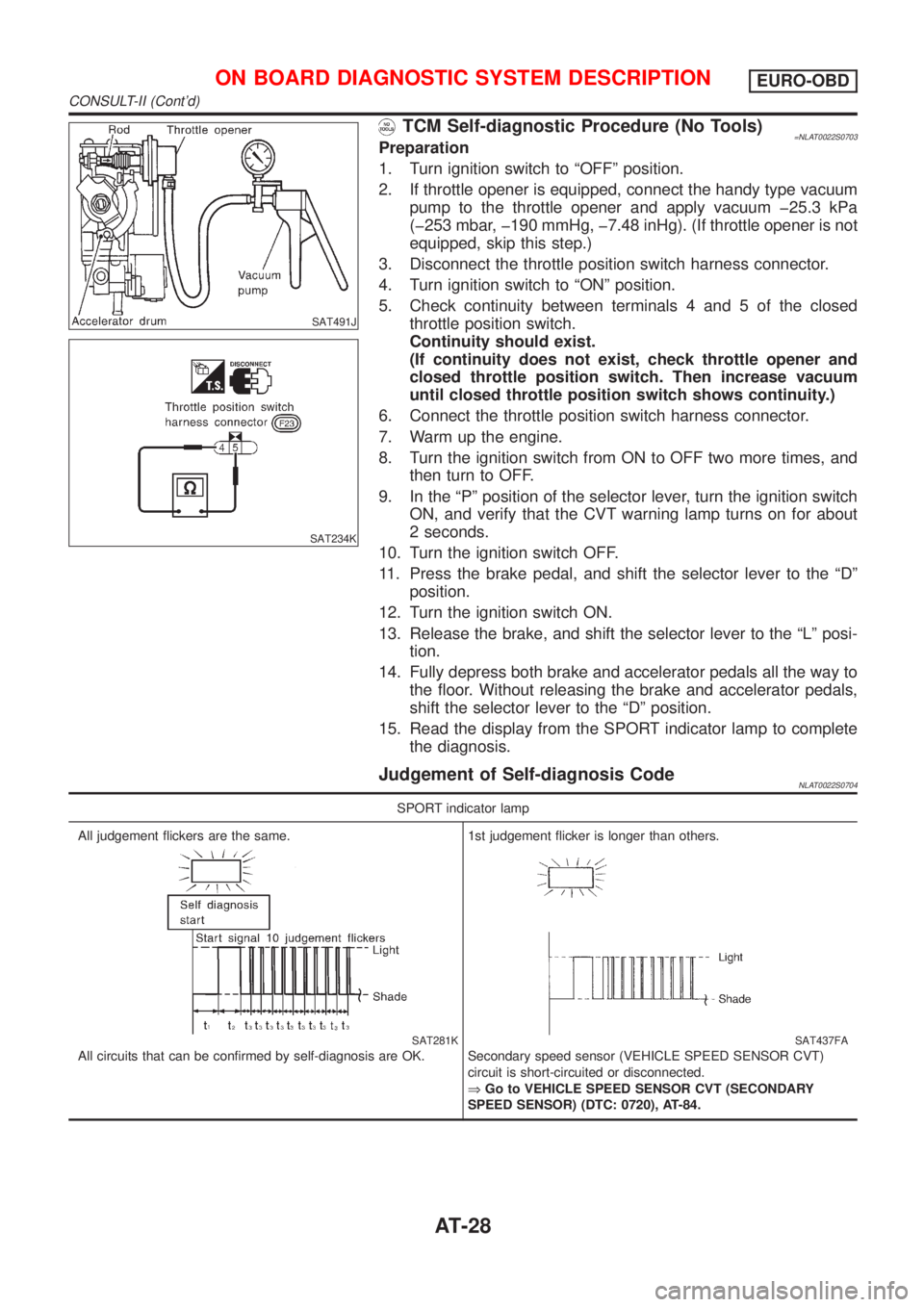
TCM Self-diagnostic Procedure (No Tools)=NLAT0022S0703Preparation
1. Turn ignition switch to ªOFFº position.
2. If throttle opener is equipped, connect the handy type vacuum
pump to the throttle opener and apply vacuum þ25.3 kPa
(þ253 mbar, þ190 mmHg, þ7.48 inHg). (If throttle opener is not
equipped, skip this step.)
3. Disconnect the throttle position switch harness connector.
4. Turn ignition switch to ªONº position.
5. Check continuity between terminals 4 and 5 of the closed
throttle position switch.
Continuity should exist.
(If continuity does not exist, check throttle opener and
closed throttle position switch. Then increase vacuum
until closed throttle position switch shows continuity.)
6. Connect the throttle position switch harness connector.
7. Warm up the engine.
8. Turn the ignition switch from ON to OFF two more times, and
then turn to OFF.
9. In the ªPº position of the selector lever, turn the ignition switch
ON, and verify that the CVT warning lamp turns on for about
2 seconds.
10. Turn the ignition switch OFF.
11. Press the brake pedal, and shift the selector lever to the ªDº
position.
12. Turn the ignition switch ON.
13. Release the brake, and shift the selector lever to the ªLº posi-
tion.
14. Fully depress both brake and accelerator pedals all the way to
the floor. Without releasing the brake and accelerator pedals,
shift the selector lever to the ªDº position.
15. Read the display from the SPORT indicator lamp to complete
the diagnosis.
Judgement of Self-diagnosis CodeNLAT0022S0704
SPORT indicator lamp
All judgement flickers are the same.
SAT281K
All circuits that can be confirmed by self-diagnosis are OK.1st judgement flicker is longer than others.
SAT437FA
Secondary speed sensor (VEHICLE SPEED SENSOR CVT)
circuit is short-circuited or disconnected.
ÞGo to VEHICLE SPEED SENSOR CVT (SECONDARY
SPEED SENSOR) (DTC: 0720), AT-84.
ON BOARD DIAGNOSTIC SYSTEM DESCRIPTIONEURO-OBD
CONSULT-II (Cont'd)
AT-28
Page 37 of 3051
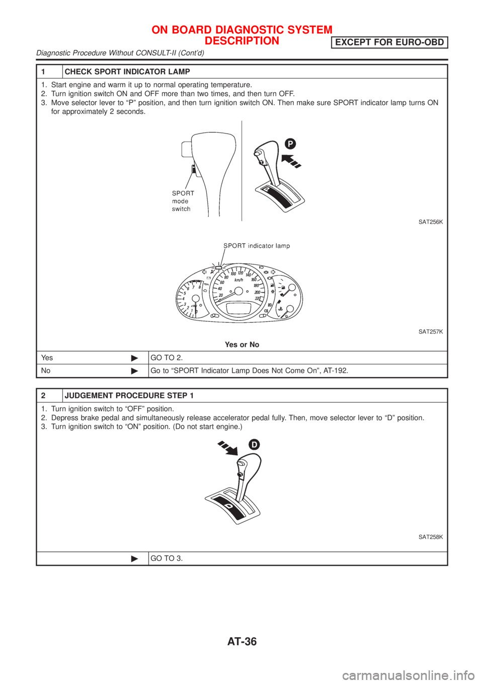
1 CHECK SPORT INDICATOR LAMP
1. Start engine and warm it up to normal operating temperature.
2. Turn ignition switch ON and OFF more than two times, and then turn OFF.
3. Move selector lever to ªPº position, and then turn ignition switch ON. Then make sure SPORT indicator lamp turns ON
for approximately 2 seconds.
SAT256K
SAT257K
YesorNo
Ye s©GO TO 2.
No©Go to ªSPORT Indicator Lamp Does Not Come Onº, AT-192.
2 JUDGEMENT PROCEDURE STEP 1
1. Turn ignition switch to ªOFFº position.
2. Depress brake pedal and simultaneously release accelerator pedal fully. Then, move selector lever to ªDº position.
3. Turn ignition switch to ªONº position. (Do not start engine.)
SAT258K
©GO TO 3.
ON BOARD DIAGNOSTIC SYSTEM
DESCRIPTION
EXCEPT FOR EURO-OBD
Diagnostic Procedure Without CONSULT-II (Cont'd)
AT-36
Page 42 of 3051
SAT631IA
SAT632I
SEF234G
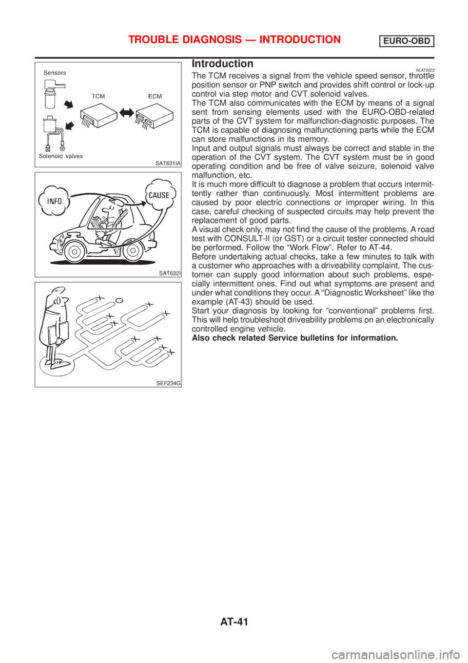
IntroductionNLAT0023The TCM receives a signal from the vehicle speed sensor, throttle
position sensor or PNP switch and provides shift control or lock-up
control via step motor and CVT solenoid valves.
The TCM also communicates with the ECM by means of a signal
sent from sensing elements used with the EURO-OBD-related
parts of the CVT system for malfunction-diagnostic purposes. The
TCM is capable of diagnosing malfunctioning parts while the ECM
can store malfunctions in its memory.
Input and output signals must always be correct and stable in the
operation of the CVT system. The CVT system must be in good
operating condition and be free of valve seizure, solenoid valve
malfunction, etc.
It is much more difficult to diagnose a problem that occurs intermit-
tently rather than continuously. Most intermittent problems are
caused by poor electric connections or improper wiring. In this
case, careful checking of suspected circuits may help prevent the
replacement of good parts.
A visual check only, may not find the cause of the problems. A road
test with CONSULT-II (or GST) or a circuit tester connected should
be performed. Follow the ªWork Flowº. Refer to AT-44.
Before undertaking actual checks, take a few minutes to talk with
a customer who approaches with a driveability complaint. The cus-
tomer can supply good information about such problems, espe-
cially intermittent ones. Find out what symptoms are present and
under what conditions they occur. A ªDiagnostic Worksheetº like the
example (AT-43) should be used.
Start your diagnosis by looking for ªconventionalº problems first.
This will help troubleshoot driveability problems on an electronically
controlled engine vehicle.
Also check related Service bulletins for information.
TROUBLE DIAGNOSIS Ð INTRODUCTIONEURO-OBD
AT-41
Page 44 of 3051
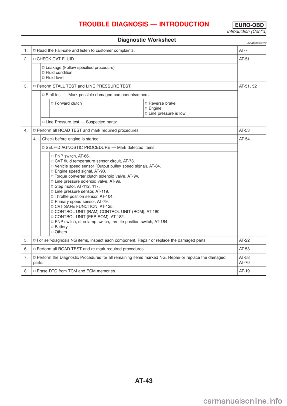
Diagnostic Worksheet=NLAT0023S0102
1.NRead the Fail-safe and listen to customer complaints. AT-7
2.NCHECK CVT FLUIDAT-51
NLeakage (Follow specified procedure)
NFluid condition
NFluid level
3.NPerform STALL TEST and LINE PRESSURE TEST. AT-51, 52
NStall test Ð Mark possible damaged components/others.
NForward clutchNReverse brake
NEngine
NLine pressure is low.
NLine Pressure test Ð Suspected parts:
4.NPerform all ROAD TEST and mark required procedures. AT-53
4-1. Check before engine is started.AT-54
NSELF-DIAGNOSTIC PROCEDURE Ð Mark detected items.
NPNP switch, AT-66.
NCVT fluid temperature sensor circuit, AT-73.
NVehicle speed sensor (Output pulley speed signal), AT-84.
NEngine speed signal, AT-90.
NTorque converter clutch solenoid valve, AT-94.
NLine pressure solenoid valve, AT-99.
NStep motor, AT-112, 117.
NLine pressure sensor, AT-119.
NThrottle position sensor, AT-104.
NPrimary speed sensor, AT-79.
NCVT SAFE FUNCTION, AT-125.
NCONTROL UNIT (RAM) CONTROL UNIT (ROM), AT-180.
NCONTROL UNIT (EEP ROM), AT-182.
NPNP switch, stop lamp switch, throttle position switch, AT-184.
NBattery
NOthers
5.NFor self-diagnosis NG items, inspect each component. Repair or replace the damaged parts. AT-22
6.NPerform all ROAD TEST and re-mark required procedures. AT-53
7.NPerform the Diagnostic Procedures for all remaining items marked NG. Repair or replace the damaged
parts.AT-58
AT-70
8.NErase DTC from TCM and ECM memories. AT-19
TROUBLE DIAGNOSIS Ð INTRODUCTIONEURO-OBD
Introduction (Cont'd)
AT-43
Page 47 of 3051
SAT631IA
SAT632I
SEF234G
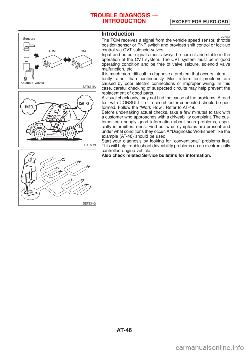
IntroductionNLAT0247The TCM receives a signal from the vehicle speed sensor, throttle
position sensor or PNP switch and provides shift control or lock-up
control via CVT solenoid valves.
Input and output signals must always be correct and stable in the
operation of the CVT system. The CVT system must be in good
operating condition and be free of valve seizure, solenoid valve
malfunction, etc.
It is much more difficult to diagnose a problem that occurs intermit-
tently rather than continuously. Most intermittent problems are
caused by poor electric connections or improper wiring. In this
case, careful checking of suspected circuits may help prevent the
replacement of good parts.
A visual check only, may not find the cause of the problems. A road
test with CONSULT-II or a circuit tester connected should be per-
formed. Follow the ªWork Flowº. Refer to AT-49.
Before undertaking actual checks, take a few minutes to talk with
a customer who approaches with a driveability complaint. The cus-
tomer can supply good information about such problems, espe-
cially intermittent ones. Find out what symptoms are present and
under what conditions they occur. A ªDiagnostic Worksheetº like the
example (AT-48) should be used.
Start your diagnosis by looking for ªconventionalº problems first.
This will help troubleshoot driveability problems on an electronically
controlled engine vehicle.
Also check related Service bulletins for information.
TROUBLE DIAGNOSIS Ð
INTRODUCTION
EXCEPT FOR EURO-OBD
AT-46