check engine NISSAN ALMERA TINO 2001 Service Repair Manual
[x] Cancel search | Manufacturer: NISSAN, Model Year: 2001, Model line: ALMERA TINO, Model: NISSAN ALMERA TINO 2001Pages: 3051, PDF Size: 46.38 MB
Page 3002 of 3051

Checking and Adjusting Drive BeltsNLST0011Refer to EM-17,“Checking Drive Belts”.
SMA851B
Checking Steering Gear and LinkageNLST0037STEERING GEARNLST0037S01+Check gear housing and boots for looseness, damage or
grease leakage.
+Check connection with steering column for looseness.
STEERING LINKAGENLST0037S02+Check ball joint, dust cover and other component parts for
looseness, wear, damage or grease leakage.
YST003
Checking Fluid LevelNLST0012Check fluid level, referring to the scale on reservoir tank.
Use“HOT”range for fluid temperatures of 50 to 80°C (122 to
176°F).
Use“COLD”range for fluid temperatures of 0 to 30°C (32 to 86°F).
CAUTION:
+Do not overfill.
+Recommended fluid is DEXRON
TMIII or equivalent. Refer
to MA-20,“Fluids and Lubricants”.
YST004
YST005
Checking Fluid LeakageNLST0013Check the lines for improper attachment and for leaks, cracks,
damage, loose connections, chafing and deterioration.
1. Run engine between idle speed and 1,000 rpm.
Make sure temperature of fluid in oil tank rises to 60 to 80°C
(140 to 176°F).
2. Turn steering wheel right-to-left several times.
3. Hold steering wheel at each“lock”position for five seconds
and carefully check for fluid leakage.
CAUTION:
Do not hold the steering wheel in a locked position for more
than 15 seconds.
4. If fluid leakage at connectors is noticed, loosen flare nut and
then retighten.
Do not overtighten connector as this can damage O-ring,
washer and connector.
5. If fluid leakage from power steering pump is noticed, check
power steering pump. Refer to ST-21.
6. Check rack boots for accumulation of power steering fluid.
ON-VEHICLE SERVICE
Checking and Adjusting Drive Belts
ST-7
Page 3003 of 3051
Bleeding Hydraulic SystemNLST00141. Raise front end of vehicle until wheels are clear of the ground.
2. Add fluid into oil tank to specified level. Then quickly turn steer-
ing wheel fully to right and left and lightly touch steering stop-
pers.
Repeat steering wheel operation until fluid level no longer
decreases.
3. Start engine.
Repeat step 2. above.
+Incomplete air bleeding will cause the following to occur. When
this happens, bleed air again.
a) Air bubbles in reservoir tank
b) Clicking noise in oil pump
c) Excessive buzzing in oil pump
Fluid noise may occur in the valve or oil pump. This is common
when the vehicle is stationary or while turning the steering wheel
slowly. This does not affect the performance or durability of the
system.
SST491B
SST090B
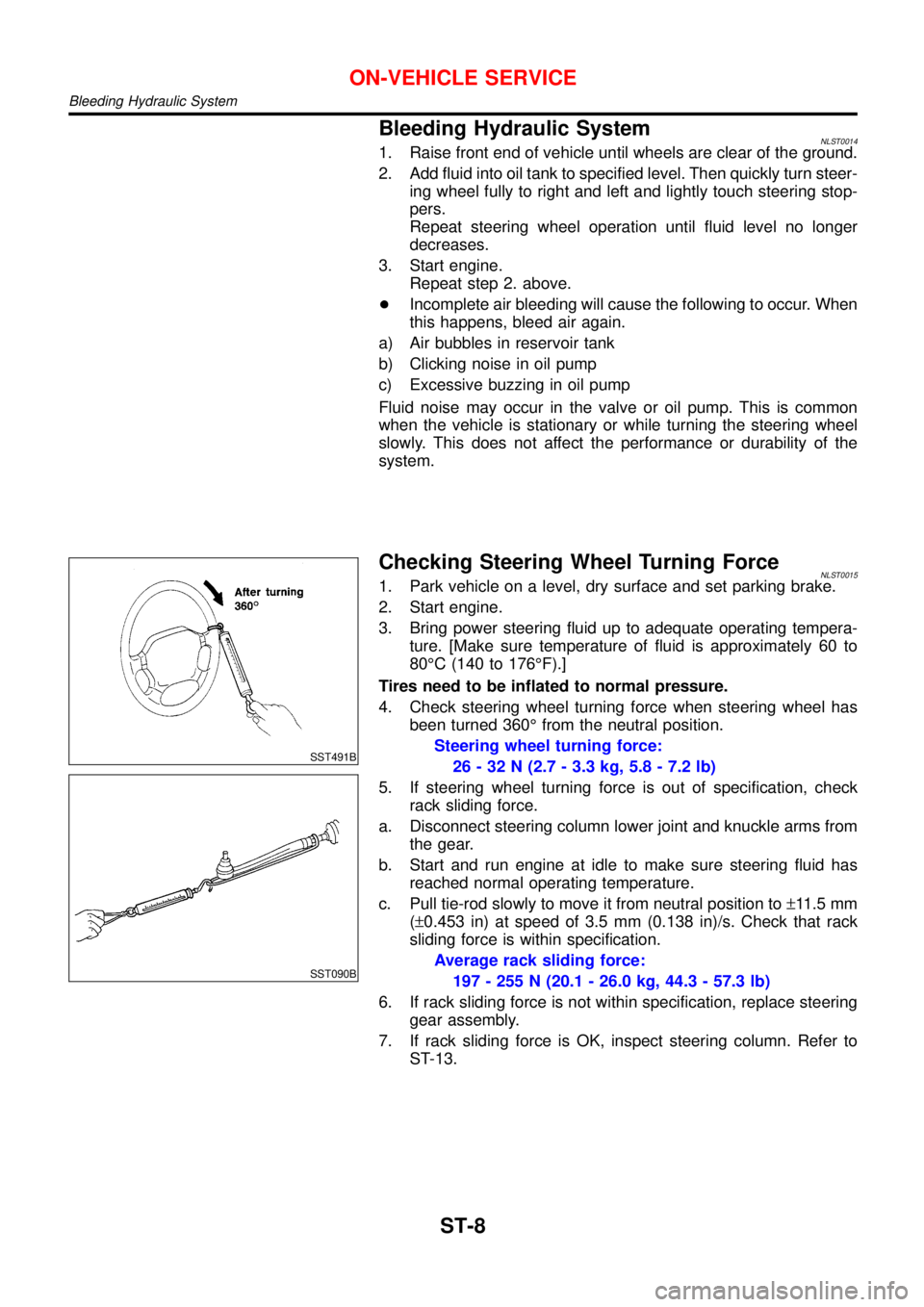
Checking Steering Wheel Turning ForceNLST00151. Park vehicle on a level, dry surface and set parking brake.
2. Start engine.
3. Bring power steering fluid up to adequate operating tempera-
ture. [Make sure temperature of fluid is approximately 60 to
80°C (140 to 176°F).]
Tires need to be inflated to normal pressure.
4. Check steering wheel turning force when steering wheel has
been turned 360°from the neutral position.
Steering wheel turning force:
26 - 32 N (2.7 - 3.3 kg, 5.8 - 7.2 lb)
5. If steering wheel turning force is out of specification, check
rack sliding force.
a. Disconnect steering column lower joint and knuckle arms from
the gear.
b. Start and run engine at idle to make sure steering fluid has
reached normal operating temperature.
c. Pull tie-rod slowly to move it from neutral position to±11.5 mm
(±0.453 in) at speed of 3.5 mm (0.138 in)/s. Check that rack
sliding force is within specification.
Average rack sliding force:
197 - 255 N (20.1 - 26.0 kg, 44.3 - 57.3 lb)
6. If rack sliding force is not within specification, replace steering
gear assembly.
7. If rack sliding force is OK, inspect steering column. Refer to
ST-13.
ON-VEHICLE SERVICE
Bleeding Hydraulic System
ST-8
Page 3004 of 3051
SST834-I
Checking Hydraulic SystemNLST0016Before starting, check belt tension, driving pulley and tire pressure.
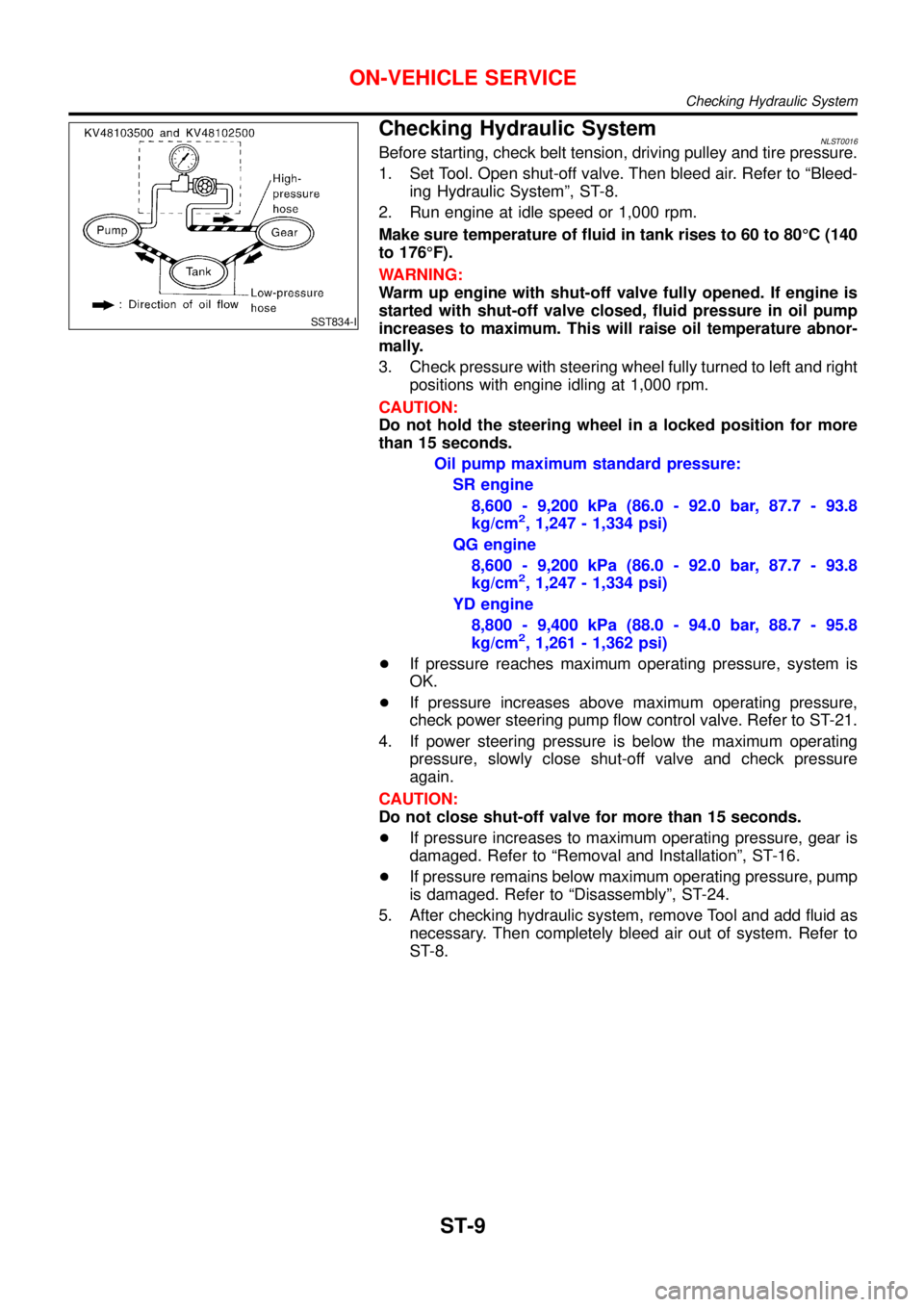
1. Set Tool. Open shut-off valve. Then bleed air. Refer to“Bleed-
ing Hydraulic System”, ST-8.
2. Run engine at idle speed or 1,000 rpm.
Make sure temperature of fluid in tank rises to 60 to 80°C (140
to 176°F).
WARNING:
Warm up engine with shut-off valve fully opened. If engine is
started with shut-off valve closed, fluid pressure in oil pump
increases to maximum. This will raise oil temperature abnor-
mally.
3. Check pressure with steering wheel fully turned to left and right
positions with engine idling at 1,000 rpm.
CAUTION:
Do not hold the steering wheel in a locked position for more
than 15 seconds.
Oil pump maximum standard pressure:
SR engine
8,600 - 9,200 kPa (86.0 - 92.0 bar, 87.7 - 93.8
kg/cm
2, 1,247 - 1,334 psi)
QG engine
8,600 - 9,200 kPa (86.0 - 92.0 bar, 87.7 - 93.8
kg/cm
2, 1,247 - 1,334 psi)
YD engine
8,800 - 9,400 kPa (88.0 - 94.0 bar, 88.7 - 95.8
kg/cm
2, 1,261 - 1,362 psi)
+If pressure reaches maximum operating pressure, system is
OK.
+If pressure increases above maximum operating pressure,
check power steering pump flow control valve. Refer to ST-21.
4. If power steering pressure is below the maximum operating
pressure, slowly close shut-off valve and check pressure
again.
CAUTION:
Do not close shut-off valve for more than 15 seconds.
+If pressure increases to maximum operating pressure, gear is
damaged. Refer to“Removal and Installation”, ST-16.
+If pressure remains below maximum operating pressure, pump
is damaged. Refer to“Disassembly”, ST-24.
5. After checking hydraulic system, remove Tool and add fluid as
necessary. Then completely bleed air out of system. Refer to
ST-8.
ON-VEHICLE SERVICE
Checking Hydraulic System
ST-9
Page 3013 of 3051

SST090B
STEERING GEARNLST0024S061. Check rack sliding force on vehicle as follows:
a. Install steering gear onto vehicle, but do not connect tie-rod to
knuckle arm.
b. Connect all piping and fill with steering fluid.
c. Start engine and bleed air completely.
d. Disconnect steering column lower joint from the gear.
e. Keep engine at idle and make sure steering fluid has reached
normal operating temperature.
f. Pull tie-rod slowly to move it from neutral position to±11.5 mm
(±0.453 in) at speed of 3.5 mm (0.138 in)/s. Check that rack
sliding force is within specification.
Average rack sliding force:
197 - 255 N (20.1 - 26.0 kg, 44.3 - 57.3 lb)
BOOTNLST0024S01+Check condition of boot. If cracked excessively, replace it.
+Check boots for accumulation of power steering fluid.
SST468C
TIE-ROD OUTER AND INNER SOCKETSNLST0024S05+Check ball joints for swinging force.
Tie-rod outer and inner ball joints swinging force“A”:
Refer to SDS, ST-28.
+Check ball joint for rotating torque.
Tie-rod outer ball joint rotating torque“B”:
Refer to SDS, ST-28.
+Check ball joints for axial end play.
Tie-rod outer and inner ball joints axial end play“C”:
Refer to SDS, ST-28.
+Check condition of dust cover. If cracked excessively, replace
outer tie-rod.
SST866C
AssemblyNLST00251. Install lock plate to rack.
a. Temporarily install spacer ring to rack.
Discard old spacer ring; replace with a new one.
b. Install lock plate to inner socket.
Discard old lock plate; replace with a new one.
c. Apply a coat of locking sealant to inner socket threads. Screw
inner socket into rack and tighten to specified torque.
d. Clinch lock plate at rack groove location (at two points).
e. Install spacer ring to lock plate as shown in the Figure at left.
POWER STEERING GEAR AND LINKAGE
Inspection (Cont’d)
ST-18
Page 3015 of 3051

SST090B
AdjustmentNLST00261. Check rack sliding force on vehicle as follows:
a. Install steering gear onto vehicle, but do not connect tie-rod to
knuckle arm.
b. Connect all piping and fill with steering fluid.
c. Start engine and bleed air completely.
d. Disconnect steering column lower joint from the gear.
e. Keep engine at idle and make sure steering fluid has reached
normal operating temperature.
f. Pull tie-rod slowly to move it from neutral position to±11.5 mm
(±0.453 in) at speed of 3.5 mm (0.138 in)/s. Check that rack
sliding force is within specification.
Average rack sliding force:
197 - 255 N (20.1 - 26.0 kg, 44.3 - 57.3 lb)
POWER STEERING GEAR AND LINKAGE
Adjustment
ST-20
Page 3025 of 3051

SBR686C
Precautions
PRECAUTIONSNLSU0001+When installing rubber parts, final tightening must be car-
ried out under unladen condition* with tires on ground.
Oil will shorten the life of rubber bushes. Be sure to wipe
off any spilled oil.
*: Fuel, radiator coolant and engine oil full. Spare tire, jack,
hand tools and mats in designated positions.
+After installing removed suspension parts, check wheel
alignment and adjust if necessary.
+Use flare nut wrench when removing or installing brake
tubes.
+Always torque brake lines when installing.
+Lock nuts are unreusable parts; always use new ones.
When replacing, do not wipe the oil off the new lock nut
before tightening.
Preparation
SPECIAL SERVICE TOOLSNLSU0002
Tool number
Tool nameDescription
HT72520000
Ball joint remover
NT146
Removing tie-rod outer end and lower ball joint
COMMERCIAL SERVICE TOOLSNLSU0003
Tool name Description
Attachment Wheel align-
ment
NT148
Measure wheel alignment
a: Screw M24 x 1.5 pitch
b: 35 mm (1.38 in) dia.
c: 65 mm (2.56 in) dia.
d: 56 mm (2.20 in)
e: 12 mm (0.47 in)
1 Flare nut crowfoot
2 Torque wrench
NT360
Removing and installing each brake piping
a: 10 mm (0.39 in)
FRONT SUSPENSION
Precautions
SU-2
Page 3029 of 3051

SMA525A
On-vehicle Service
FRONT SUSPENSION PARTSNLSU0006Check front axle and front suspension parts for excessive play,
cracks, wear or other damage.
+Shake each front wheel to check for excessive play.
+Make sure that cotter pin is inserted.
+Retighten all axle and suspension nuts and bolts to the speci-
fied torque.
Tightening torque:
Refer to “FRONT SUSPENSION”, SU-5.
SFA392B
+Check strut (shock absorber) for oil leakage or other damage.
+Check suspension ball joint for grease leakage and ball joint
dust cover for cracks or other damage.
If ball joint dust cover is cracked or damaged, replace trans-
verse link.
SFA818AA
+Check spring height from top of wheelarch to the ground.
a) Vehicle must be unladen*, parked on a level surface, and tires
checked for proper inflation and wear (tread wear indicator
must not be showing).
*: Fuel, radiator coolant and engine oil full. Spare tire, jack,
hand tools and mats in designated positions.
b) Bounce vehicle up and down several times before measuring.
Standard height: Refer to SDS, SU-16.
c) Spring height is not adjustable. If out of specification, check for
worn springs or suspension parts.
SSU031
+Check suspension ball joint end play.
a) Jack up front of vehicle and set the stands.
b) Clamp dial indicator onto transverse link and place indicator tip
on lower edge of brake caliper.
c) Make sure front wheels are straight and brake pedal is
depressed.
d) Place a pry bar between transverse link and inner rim of road
wheel.
e) While raising and releasing pry bar, observe maximum dial
indicator value.
Vertical end play: 0 mm (0 in)
f) If ball joint movement is beyond specifications, remove and
replace it.
BALANCING WHEELSNLSU0042+Adjust wheel balance using road wheel center.
Wheel balance (Maximum allowable unbalance):
Refer to SDS, SU-16.
FRONT SUSPENSION
On-vehicle Service
SU-6
Page 3031 of 3051

SMA829C
TIRE ROTATIONNLSU0043+Do not include the T-type spare tire when rotating the tires.
Wheel nuts:
:98-118N·m (10.0 - 12.0 kg-m, 72 - 87 ft-lb)
FRONT WHEEL ALIGNMENTNLSU0045Before checking front wheel alignment, be sure to make a prelimi-
nary inspection (Unladen*).
*: Fuel, radiator coolant and engine oil full. Spare tire, jack, hand
tools and mats in designated positions.
SRA096A
Camber, Caster and Kingpin InclinationNLSU0045S01Camber, caster and kingpin inclination are preset at factory
and cannot be adjusted.
1. Measure camber, caster and kingpin inclination of both right
and left wheels with a suitable alignment gauge.
Camber, caster and kingpin inclination:
Refer to SDS, SU-15.
2. If camber, caster or kingpin inclination is not within
specification, inspect front suspension parts. Replace dam-
aged or worn out parts.
AFA050
Toe-inNLSU0045S02Measure toe-in using the following procedure.
WARNING:
+Always perform the following procedure on a flat surface.
+Make sure that no person is in front of the vehicle before
pushing it.
1. Bounce front of vehicle up and down to stabilize the posture.
2. Push the vehicle straight ahead about 5 m (16 ft).
3. Put a mark on base line of tread (rear side) of both tires at the
same height as hub center. These are measuring points.
SFA234AC
4. Measure distance“A”(rear side).
5. Push the vehicle slowly ahead to rotate the wheels 180
degrees (1/2 turn).
If the wheels have rotated more than 180 degrees (1/2 turn), try
the above procedure again from the beginning. Never push
vehicle backward.
6. Measure distance“B”(front side).
Total toe-in:
Refer to SDS, SU-15.
FRONT SUSPENSION
On-vehicle Service (Cont’d)
SU-8
Page 3040 of 3051

SBR686C
Precautions
PRECAUTIONSNLSU0024+When installing each rubber part, final tightening must be
carried out under unladen condition* with tires on ground.
Oil will shorten the life of rubber bushes. Be sure to wipe
off any spilled oil.
*: Fuel, radiator coolant and engine oil full. Spare tire, jack,
hand tools and mats in designated positions.
+Use flare nut wrench when removing or installing brake
tubes.
+After installing removed suspension parts, check wheel
alignment.
+Do not jack up at the trailing arm and lateral link.
+Always torque brake lines when installing.
+Lock nuts are unreusable parts; always use new ones.
When replacing, do not wipe the oil off of the new lock nut
before tightening.
Preparation
COMMERCIAL SERVICE TOOLSNLSU0026
Tool name Description
Equivalent to
1 Flare nut crowfoot
2 Torque wrench
NT360
Removing and installing brake piping
a: 10 mm (0.39 in)
Spring compressor
NT717
Removing and installing coil spring
Noise, Vibration and Harshness (NVH)
Troubleshooting
NLSU0027Refer to“Noise, Vibration and Harshness (NVH) Troubleshooting”,
“FRONT SUSPENSION”, SU-4.
REAR SUSPENSION
Precautions
SU-17
Page 3042 of 3051

SMA525A
On-vehicle Service
REAR SUSPENSION PARTSNLSU0029Check axle and suspension parts for excessive play, wear or dam-
age.
+Shake each rear wheel to check for excessive play.
SSU036
+Retighten all nuts and bolts to the specified torque.
Tightening torque:
Refer to“REAR SUSPENSION”, SU-18.
SMA113
+Check shock absorber for oil leakage or other damage.
+Check wheelarch height. Refer to“On-vehicle Service”,
“FRONT SUSPENSION PARTS”, SU-6.
REAR WHEEL ALIGNMENTNLSU0030Before checking rear wheel alignment, be sure to make a prelimi-
nary inspection (Unladen*).
*: Fuel, radiator coolant and engine oil full. Spare tire, jack, hand
tools and mats in designated positions.
SFA975B
Preliminary InspectionNLSU0030S01Aluminum wheelNLSU0030S01011. Check tires for wear and improper inflation.
2. Check wheels for deformation, cracks and other damage. If
deformed, remove wheel and check wheel runout.
a. Remove tire from aluminum wheel and mount on a tire balance
machine.
b. Set dial indicator as shown in the illustration.
Wheel runout (Dial indicator value):
Refer to SDS, SU-16.
3. Check front wheel bearings for looseness.
REAR SUSPENSION
On-vehicle Service
SU-19