NISSAN ALTIMA 1997 U13 / 1.G Owners Manual
Manufacturer: NISSAN, Model Year: 1997, Model line: ALTIMA, Model: NISSAN ALTIMA 1997 U13 / 1.GPages: 203, PDF Size: 1.64 MB
Page 151 of 203

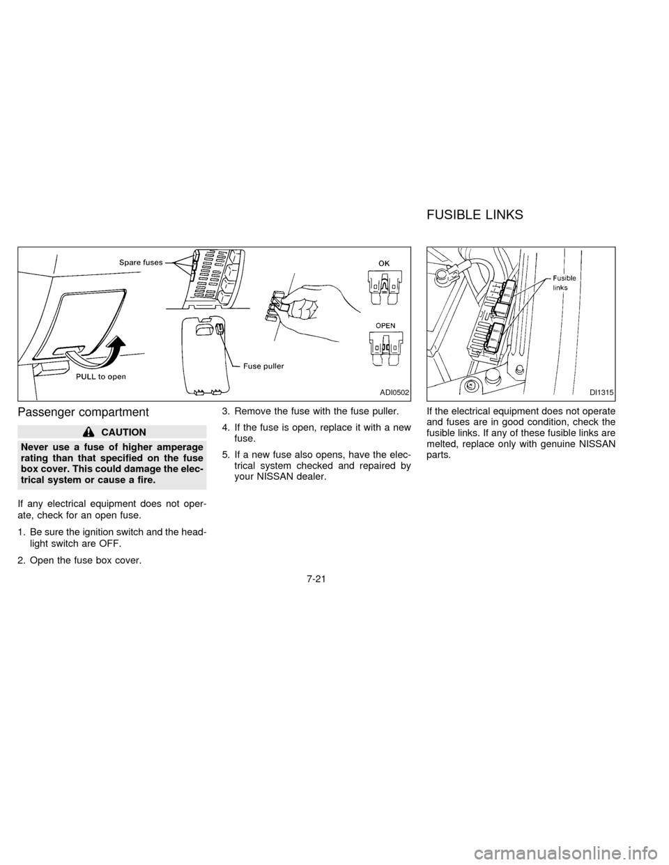
Passenger compartment
CAUTION
Never use a fuse of higher amperage
rating than that specified on the fuse
box cover. This could damage the elec-
trical system or cause a fire.
If any electrical equipment does not oper-
ate, check for an open fuse.
1. Be sure the ignition switch and the head-
light switch are OFF.
2. Open the fuse box cover.3. Remove the fuse with the fuse puller.
4. If the fuse is open, replace it with a new
fuse.
5. If a new fuse also opens, have the elec-
trical system checked and repaired by
your NISSAN dealer.If the electrical equipment does not operate
and fuses are in good condition, check the
fusible links. If any of these fusible links are
melted, replace only with genuine NISSAN
parts.
ADI0502DI1315
FUSIBLE LINKS
7-21
ZX
Page 152 of 203

HEADLIGHTS
The headlight is a semi-sealed beam type
which uses a replaceable headlight (halo-
gen) bulb.
CAUTION
cHigh pressure halogen gas is sealed
inside the halogen bulb. The bulb
may break if the glass envelope is
scratched or the bulb is dropped.
cWhen handling the bulb, do not
touch the glass envelope.
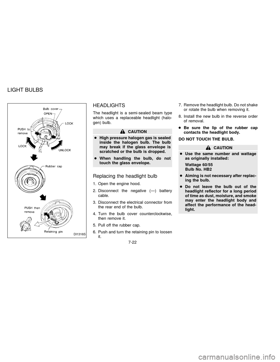
Replacing the headlight bulb
1. Open the engine hood.
2. Disconnect the negative (Ð) battery
cable.
3. Disconnect the electrical connector from
the rear end of the bulb.
4. Turn the bulb cover counterclockwise,
then remove it.
5. Pull off the rubber cap.
6. Push and turn the retaining pin to loosen
it.7. Remove the headlight bulb. Do not shake
or rotate the bulb when removing it.
8. Install the new bulb in the reverse order
of removal.
cBe sure the lip of the rubber cap
contacts the headlight body.
DO NOT TOUCH THE BULB.
CAUTION
cUse the same number and wattage
as originally installed:
Wattage 60/55
Bulb No. HB2
cAiming is not necessary after replac-
ing the bulb.
cDo not leave the bulb out of the
headlight reflector for a long period
of time as dust, moisture, and smoke
may enter the headlight body and
affect the performance of the head-
light.
DI1316S
LIGHT BULBS
7-22
ZX
Page 153 of 203

HEADLIGHT AIMING
ADJUSTMENT
Before performing aiming adjustment, make
sure of the following:
a. Keep all of the tires inflated to the correct
pressure.
b. Place the vehicle on level ground.
c. See that the vehicle is unloaded (except
for full levels of coolant, engine oil and
fuel, and spare tire, jack, and tools).
Have the driver or an equivalent weight
placed in the driver's seat.
Low beam
1. Open the hood.
2. Adjust the vertical indicator by turning the
adjusting screw with a Phillips screw-
driver. The bubble in the gauge should
be centered on the ``0'' mark.3. Adjust the horizontal indicator by turning
the adjusting screw with a Phillips screw-
driver.
The inner red line with the ``0'' mark
should align with the indicator line. Never
turn screw
sAas indicated in earlier
illustration.
ADI0085ADI0526ADI0096
7-23
ZX
Page 154 of 203

ADJUSTMENT AFTER
HEADLIGHT ASSEMBLY
REPLACEMENT
If the vehicle has had front body repair and
the headlight assembly has been replaced,
the aiming should be checked using the
aiming chart as shown in the illustration.
a. Adjust headlights so that main axis of
light is parallel to center line of body
and is aligned with point P shown in
the illustration.
b. Dotted lines in illustration show cen-
ter of headlight.
H: Horizontal center line of head-
lights
W: Distance between each headlight
center
L: Distance between the headlights
and the wall that the lights are
tested against. 7.62 m (25 ft)
C: Distance below the horizontal cen-
ter line of the light (ªHº) used in
determining the main axis of light.
106 mm (4.17 in)
H-C=M
M = main axis of lightEven if the horizontal indicator does not
align with the indicator line or the bubble is
not centered in the water level after aiming
by the chart, it is acceptable if the lines are
within the OK ranges.
ADI0505
7-24
ZX
Page 155 of 203

BULB REPLACEMENT
Item Wattage (W) Bulb No.
Headlight (Semi-sealed beam)
High/Low 60/55 HB2
Cornering light/Front parking light
127/5 1157
Front parking light25 168
Front turn signal light 27 1156NA
Front side marker light 3.8 194
Front fog light 55 H3
Rear combination light:
Turn signal 27 1156NA
Stop/Tail 27/8 1157
Back-up 27 1156
Rear side marker light 3.8 194
License plate light 5 168
High-mounted stop light 13 912
Interior light 8
Front personal light 10
Trunk light 3.4 158
Glove box light (if so equipped) 3.4 158
1: Models with cornering light
2: Models without cornering light
7-25
ZX
Page 156 of 203

Replacement procedures
All other lights are either type A, B, C or D.
When replacing a bulb, first remove the lens
and/or cover.
ADI0530
DI1029M
7-26
ZX
Page 157 of 203

ADI0531
7-27
ZX
Page 158 of 203

ADI0503S
7-28
ZX
Page 159 of 203

If you have a flat tire, see the ``In case of
emergency'' section.
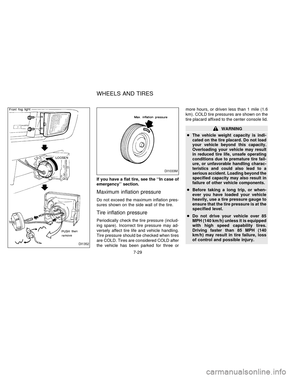
Maximum inflation pressure
Do not exceed the maximum inflation pres-
sures shown on the side wall of the tire.
Tire inflation pressure
Periodically check the tire pressure (includ-
ing spare). Incorrect tire pressure may ad-
versely affect tire life and vehicle handling.
Tire pressure should be checked when tires
are COLD. Tires are considered COLD after
the vehicle has been parked for three ormore hours, or driven less than 1 mile (1.6
km). COLD tire pressures are shown on the
tire placard affixed to the center console lid.
WARNING
c
The vehicle weight capacity is indi-
cated on the tire placard. Do not load
your vehicle beyond this capacity.
Overloading your vehicle may result
in reduced tire life, unsafe operating
conditions due to premature tire fail-
ure, or unfavorable handling charac-
teristics and could also lead to a
serious accident. Loading beyond the
specified capacity may also result in
failure of other vehicle components.
cBefore taking a long trip, or when-
ever you have loaded your vehicle
heavily, use a tire pressure gauge to
ensure that the tire pressure is at the
specified level.
cDo not drive your vehicle over 85
MPH (140 km/h) unless it is equipped
with high speed capability tires.
Driving faster than 85 MPH (140
km/h) may result in tire failure, loss
of control and possible injury.
DI1352
DI1033M
WHEELS AND TIRES
7-29
ZX
Page 160 of 203

Types of tires
CAUTION
When changing or replacing tires, be
sure all four tires are of the same type
(i.e., Summer, All Season or Snow) and
construction. Your NISSAN dealer may
be able to help you with information
about tire type, size, speed rating and
availability. Replacement tires may
have a lower speed rating than the
factory equipped tires, and may not
match the potential maximum vehicle
speed. Never exceed the maximum
speed rating of the tire.
All Season tires
NISSAN specifies All Season tires on some
models to provide good performance for
use all year around, including snowy and icy
road conditions. All Season Tires are iden-
tified by ``ALL SEASON'' and/or ``M&S'' on
the tire sidewall. Snow tires have better
snow traction than All Season tires and may
be more appropriate in some areas.
Summer tires
NISSAN specifies summer tires on some
models to provide superior performance on
dry roads. Summer tire performance in
snow and ice is substantially reduced. Sum-
mer tires do not have the tire traction rating
``M&S'' on the tire sidewall.
If you plan to operate your vehicle in snowy
or icy conditions, NISSAN recommends the
use of ``SNOW'' or ``ALL SEASON'' tires on
all four wheels.
Snow tires
If snow tires are needed, it is necessary to
select tires equivalent in size and load rating
to the original equipment tires. If you do not,
it can adversely affect the safety and han-
dling of your vehicle.
Generally, snow tires have lower speed
ratings than factory equipped tires and may
not match the potential maximum vehicle
speed. Never exceed the maximum speed
rating of the tire.
For additional traction on icy roads, studded
tires may be used. However, some prov-
inces and states prohibit their use. Check
local, state and provincial laws before in-stalling studded tires. Skid and traction ca-
pabilities of studded snow tires on wet or dry
surfaces may be poorer than that of non-
studded snow tires.
Tire chains
Use of tire chains may be prohibited accord-
ing to location. Check the local laws before
installing tire chains. When installing tire
chains, make sure they are of proper size
for the tires on your vehicle and are installed
according to the chain manufacturer's sug-
gestions.Use only SAE class ``S'' chains.
Other types may damage your vehicle. Use
chain tensioners when recommended by
the tire chain manufacturer to ensure a tight
fit. Loose end links of the tire chain must be
secured or removed to prevent the possibil-
ity of whipping action damage to the fenders
or underbody. If possible, avoid fully loading
your vehicle when using tire chains. In ad-
dition, drive at a reduced speed. Otherwise,
your vehicle may be damaged and/or ve-
hicle handling and performance may be
adversely affected.
Never install tire chains on T-type spare
tires. Do not use tire chains on dry roads.
7-30
ZX