NISSAN ARMADA 2017 2.G Owners Manual
Manufacturer: NISSAN, Model Year: 2017, Model line: ARMADA, Model: NISSAN ARMADA 2017 2.GPages: 614, PDF Size: 2.87 MB
Page 91 of 614
Vehicle Dynamic Control (VDC) OFF switch ................. 2-48
Power outlet ........................................................................\
.... 2-48
Storage ........................................................................\
............. 2-50Cup holders ....................................................................... 2-50
Sunglasses holder ........................................................... 2-52
Glove box ........................................................................\
... 2-53
Console box ....................................................................... 2-54
Tray ........................................................................\
............... 2-55
Coat hooks ........................................................................\
2-55
Luggage hooks ................................................................. 2-56
Cargo floor box ................................................................. 2-56
Roof rack ........................................................................\
.... 2-57
Rear bumper cover .......................................................... 2-58
Windows ........................................................................\
.......... 2-59
Power windows ................................................................ 2-59
Moonroof (if so equipped) ................................................... 2-62 Power moonroof ............................................................... 2-62 Welcome light (if so equipped) ......................................... 2-64
Battery saver system ................................................... 2-64
Interior lights ........................................................................\
... 2-65 Map lights ........................................................................\
2-65
Rear personal lights ...................................................... 2-65
Interior light control switch .......................................... 2-65
Vanity mirror lights ................................................................. 2-66
Cargo light ........................................................................\
...... 2-67
HomeLink
�ŠUniversal Transceiver (if so equipped) ...... 2-67
Programming HomeLink�Š............................................. 2-68
Programming HomeLink�Šfor Canadian customers
and gate openers ........................................................... 2-69
Operating the HomeLink
�Š
Universal Transceiver .................................................... 2-69
Programming troubleshooting ..................................... 2-70
Clearing the programmed information ...................... 2-70
Reprogramming a single HomeLink
�Šbutton .......... 2-70
If your vehicle is stolen ................................................. 2-70
Page 92 of 614
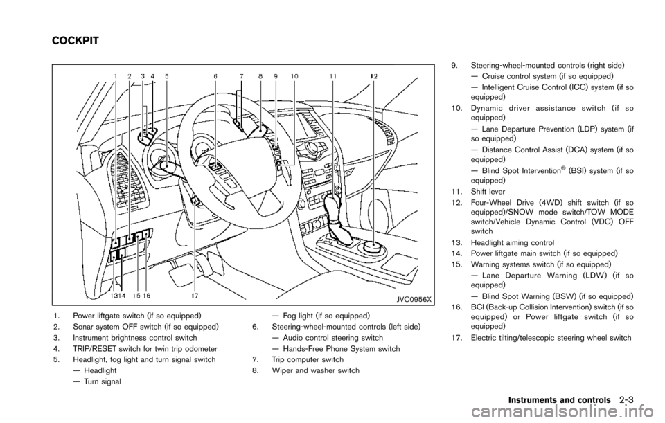
JVC0956X
1. Power liftgate switch (if so equipped)
2. Sonar system OFF switch (if so equipped)
3. Instrument brightness control switch
4. TRIP/RESET switch for twin trip odometer
5. Headlight, fog light and turn signal switch— Headlight
— Turn signal — Fog light (if so equipped)
6. Steering-wheel-mounted controls (left side) — Audio control steering switch
— Hands-Free Phone System switch
7. Trip computer switch
8. Wiper and washer switch 9. Steering-wheel-mounted controls (right side)
— Cruise control system (if so equipped)
— Intelligent Cruise Control (ICC) system (if so
equipped)
10. Dynamic driver assistance switch (if so equipped)
— Lane Departure Prevention (LDP) system (if
so equipped)
— Distance Control Assist (DCA) system (if so
equipped)
— Blind Spot Intervention
�Š(BSI) system (if so
equipped)
11. Shift lever
12. Four-Wheel Drive (4WD) shift switch (if so equipped)/SNOW mode switch/TOW MODE
switch/Vehicle Dynamic Control (VDC) OFF
switch
13. Headlight aiming control
14. Power liftgate main switch (if so equipped)
15. Warning systems switch (if so equipped) — Lane Departure Warning (LDW) (if so
equipped)
— Blind Spot Warning (BSW) (if so equipped)
16. BCI (Back-up Collision Intervention) switch (if so equipped) or Power liftgate switch (if so
equipped)
17. Electric tilting/telescopic steering wheel switch
Instruments and controls2-3
COCKPIT
Page 93 of 614
2-4Instruments and controls
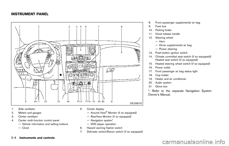
JVC0957X
1. Side ventilator
2. Meters and gauges
3. Center ventilator
4. Center multi-function control panel— Vehicle information and setting buttons
— Clock 5. Center display
— Around View�ŠMonitor (if so equipped)
— RearView Monitor (if so equipped)
— Navigation system*
— DVD player operation
6. Hazard warning flasher switch
7. Defroster switch/Deicer switch (if so equipped) 8. Front passenger supplemental air bag
9. Fuse box
10. Parking brake
11. Hood release handle
12. Steering wheel
— Horn
— Driver supplemental air bag
— Power steering
13. Push-button ignition switch
14. Climate controlled seat switch (if so equipped)/ Heated seat switch (if so equipped)
15. Heated steering wheel switch (if so equipped)
16. Power outlet
17. Front passenger air bag status light
18. Cup holder
19. Heater and air conditioner
20. Audio system
21. Glove box
*: Refer to the separate Navigation System
Owner’s Manual.
INSTRUMENT PANEL
Page 94 of 614
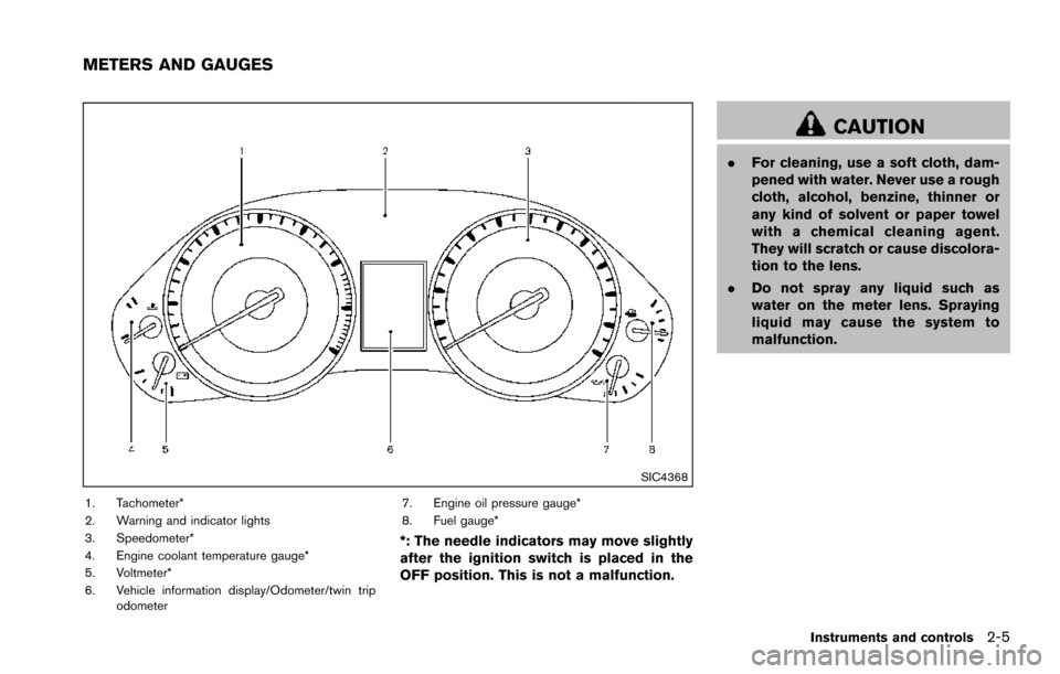
SIC4368
1. Tachometer*
2. Warning and indicator lights
3. Speedometer*
4. Engine coolant temperature gauge*
5. Voltmeter*
6. Vehicle information display/Odometer/twin tripodometer 7. Engine oil pressure gauge*
8. Fuel gauge*
*: The needle indicators may move slightly
after the ignition switch is placed in the
OFF position. This is not a malfunction.
CAUTION
.
For cleaning, use a soft cloth, dam-
pened with water. Never use a rough
cloth, alcohol, benzine, thinner or
any kind of solvent or paper towel
with a chemical cleaning agent.
They will scratch or cause discolora-
tion to the lens.
. Do not spray any liquid such as
water on the meter lens. Spraying
liquid may cause the system to
malfunction.
Instruments and controls2-5
METERS AND GAUGES
Page 95 of 614
2-6Instruments and controls
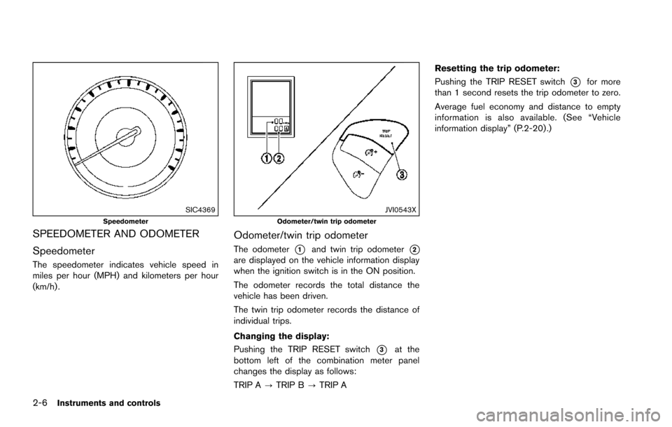
SIC4369Speedometer
SPEEDOMETER AND ODOMETER
Speedometer
The speedometer indicates vehicle speed in
miles per hour (MPH) and kilometers per hour
(km/h) .
JVI0543XOdometer/twin trip odometer
Odometer/twin trip odometer
The odometer*1and twin trip odometer*2are displayed on the vehicle information display
when the ignition switch is in the ON position.
The odometer records the total distance the
vehicle has been driven.
The twin trip odometer records the distance of
individual trips.
Changing the display:
Pushing the TRIP RESET switch
*3at the
bottom left of the combination meter panel
changes the display as follows:
TRIP A ?TRIP B ?TRIP A Resetting the trip odometer:
Pushing the TRIP RESET switch
*3for more
than 1 second resets the trip odometer to zero.
Average fuel economy and distance to empty
information is also available. (See “Vehicle
information display” (P.2-20) .)
Page 96 of 614
SIC4371
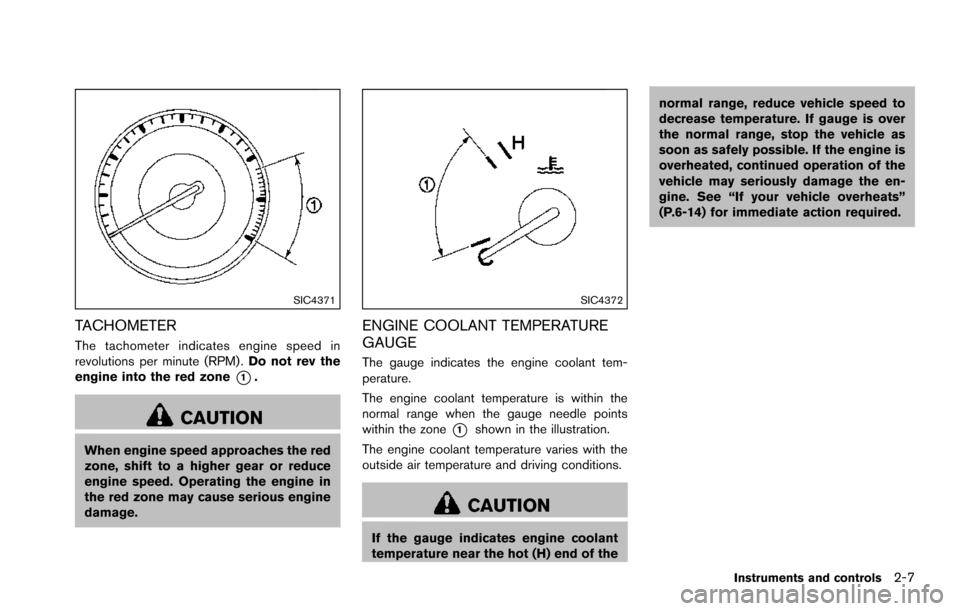
TACHOMETER
The tachometer indicates engine speed in
revolutions per minute (RPM) .Do not rev the
engine into the red zone
*1.
CAUTION
When engine speed approaches the red
zone, shift to a higher gear or reduce
engine speed. Operating the engine in
the red zone may cause serious engine
damage.
SIC4372
ENGINE COOLANT TEMPERATURE
GAUGE
The gauge indicates the engine coolant tem-
perature.
The engine coolant temperature is within the
normal range when the gauge needle points
within the zone
*1shown in the illustration.
The engine coolant temperature varies with the
outside air temperature and driving conditions.
CAUTION
If the gauge indicates engine coolant
temperature near the hot (H) end of the normal range, reduce vehicle speed to
decrease temperature. If gauge is over
the normal range, stop the vehicle as
soon as safely possible. If the engine is
overheated, continued operation of the
vehicle may seriously damage the en-
gine. See “If your vehicle overheats”
(P.6-14) for immediate action required.
Instruments and controls2-7
Page 97 of 614
2-8Instruments and controls
SIC4374
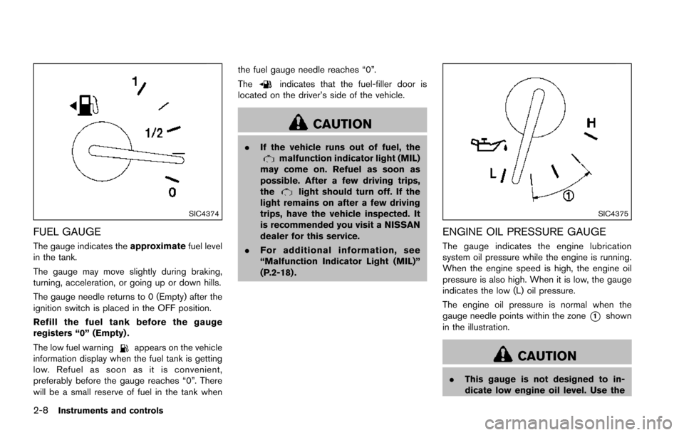
FUEL GAUGE
The gauge indicates theapproximatefuel level
in the tank.
The gauge may move slightly during braking,
turning, acceleration, or going up or down hills.
The gauge needle returns to 0 (Empty) after the
ignition switch is placed in the OFF position.
Refill the fuel tank before the gauge
registers “0” (Empty) .
The low fuel warning
appears on the vehicle
information display when the fuel tank is getting
low. Refuel as soon as it is convenient,
preferably before the gauge reaches “0”. There
will be a small reserve of fuel in the tank when the fuel gauge needle reaches “0”.
The
indicates that the fuel-filler door is
located on the driver’s side of the vehicle.
CAUTION
. If the vehicle runs out of fuel, themalfunction indicator light (MIL)
may come on. Refuel as soon as
possible. After a few driving trips,
the
light should turn off. If the
light remains on after a few driving
trips, have the vehicle inspected. It
is recommended you visit a NISSAN
dealer for this service.
. For additional information, see
“Malfunction Indicator Light (MIL)”
(P.2-18) .
SIC4375
ENGINE OIL PRESSURE GAUGE
The gauge indicates the engine lubrication
system oil pressure while the engine is running.
When the engine speed is high, the engine oil
pressure is also high. When it is low, the gauge
indicates the low (L) oil pressure.
The engine oil pressure is normal when the
gauge needle points within the zone
*1shown
in the illustration.
CAUTION
. This gauge is not designed to in-
dicate low engine oil level. Use the
Page 98 of 614
dipstick to check the oil level. (See
“Engine oil” (P.8-6) .)
. If the gauge needle does not move
with the proper amount of engine
oil, have the vehicle checked. It is
recommended you visit a NISSAN
dealer for this service. Continued
vehicle operation in such a condi-
tion could cause serious damage to
the engine.
SIC4376
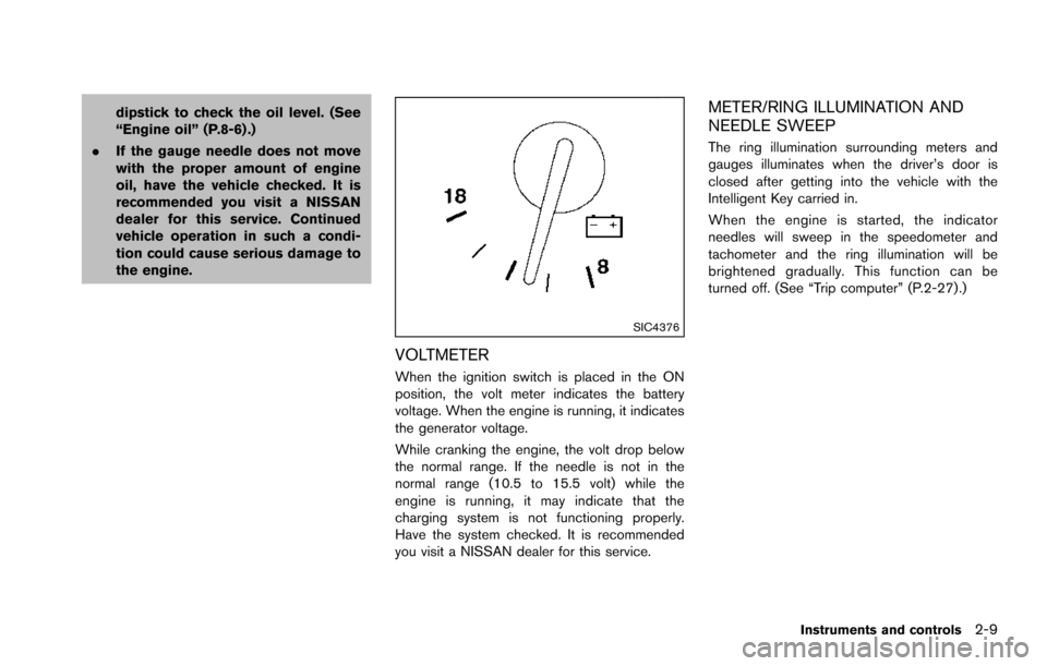
VOLTMETER
When the ignition switch is placed in the ON
position, the volt meter indicates the battery
voltage. When the engine is running, it indicates
the generator voltage.
While cranking the engine, the volt drop below
the normal range. If the needle is not in the
normal range (10.5 to 15.5 volt) while the
engine is running, it may indicate that the
charging system is not functioning properly.
Have the system checked. It is recommended
you visit a NISSAN dealer for this service.
METER/RING ILLUMINATION AND
NEEDLE SWEEP
The ring illumination surrounding meters and
gauges illuminates when the driver’s door is
closed after getting into the vehicle with the
Intelligent Key carried in.
When the engine is started, the indicator
needles will sweep in the speedometer and
tachometer and the ring illumination will be
brightened gradually. This function can be
turned off. (See “Trip computer” (P.2-27) .)
Instruments and controls2-9
Page 99 of 614
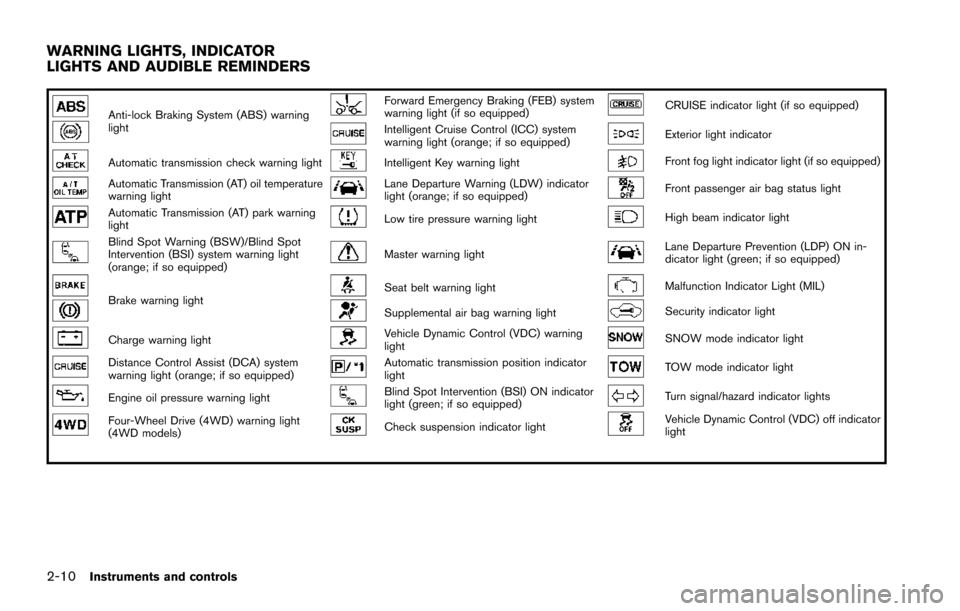
2-10Instruments and controls
Anti-lock Braking System (ABS) warning
lightForward Emergency Braking (FEB) system
warning light (if so equipped)CRUISE indicator light (if so equipped)
Intelligent Cruise Control (ICC) system
warning light (orange; if so equipped)Exterior light indicator
Automatic transmission check warning lightIntelligent Key warning lightFront fog light indicator light (if so equipped)
Automatic Transmission (AT) oil temperature
warning lightLane Departure Warning (LDW) indicator
light (orange; if so equipped)Front passenger air bag status light
Automatic Transmission (AT) park warning
lightLow tire pressure warning lightHigh beam indicator light
Blind Spot Warning (BSW)/Blind Spot
Intervention (BSI) system warning light
(orange; if so equipped)Master warning lightLane Departure Prevention (LDP) ON in-
dicator light (green; if so equipped)
Brake warning lightSeat belt warning lightMalfunction Indicator Light (MIL)
Supplemental air bag warning lightSecurity indicator light
Charge warning lightVehicle Dynamic Control (VDC) warning
lightSNOW mode indicator light
Distance Control Assist (DCA) system
warning light (orange; if so equipped)Automatic transmission position indicator
lightTOW mode indicator light
Engine oil pressure warning lightBlind Spot Intervention (BSI) ON indicator
light (green; if so equipped)Turn signal/hazard indicator lights
Four-Wheel Drive (4WD) warning light
(4WD models)Check suspension indicator lightVehicle Dynamic Control (VDC) off indicator
light
WARNING LIGHTS, INDICATOR
LIGHTS AND AUDIBLE REMINDERS
Page 100 of 614
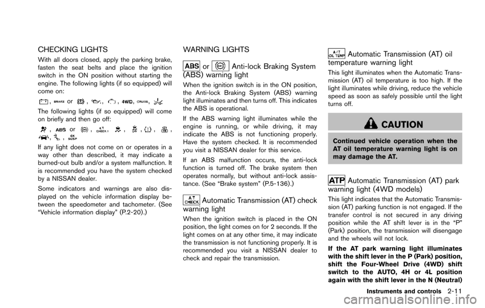
CHECKING LIGHTS
With all doors closed, apply the parking brake,
fasten the seat belts and place the ignition
switch in the ON position without starting the
engine. The following lights (if so equipped) will
come on:
,or,,,,,
The following lights (if so equipped) will come
on briefly and then go off:
,or,,,,,,,,
If any light does not come on or operates in a
way other than described, it may indicate a
burned-out bulb and/or a system malfunction. It
is recommended you have the system checked
by a NISSAN dealer.
Some indicators and warnings are also dis-
played on the vehicle information display be-
tween the speedometer and tachometer. (See
“Vehicle information display” (P.2-20) .)
WARNING LIGHTS
orAnti-lock Braking System
(ABS) warning light
When the ignition switch is in the ON position,
the Anti-lock Braking System (ABS) warning
light illuminates and then turns off. This indicates
the ABS is operational.
If the ABS warning light illuminates while the
engine is running, or while driving, it may
indicate the ABS is not functioning properly.
Have the system checked. It is recommended
you visit a NISSAN dealer for this service.
If an ABS malfunction occurs, the anti-lock
function is turned off. The brake system then
operates normally, but without anti-lock assis-
tance. (See “Brake system” (P.5-136) .)
Automatic Transmission (AT) check
warning light
When the ignition switch is placed in the ON
position, the light comes on for 2 seconds. If the
light comes on at any other time, it may indicate
the transmission is not functioning properly. It is
recommended you visit a NISSAN dealer to
check and repair the transmission.
Automatic Transmission (AT) oil
temperature warning light
This light illuminates when the Automatic Trans-
mission (AT) oil temperature is too high. If the
light illuminates while driving, reduce the vehicle
speed as soon as safely possible until the light
turns off.
CAUTION
Continued vehicle operation when the
AT oil temperature warning light is on
may damage the AT.
Automatic Transmission (AT) park
warning light (4WD models)
This light indicates that the Automatic Transmis-
sion (AT) parking function is not engaged. If the
transfer control is not secured in any driving
position while the AT shift lever is in the “P”
(Park) position, the transmission will disengage
and the wheels will not lock.
If the AT park warning light illuminates
with the shift lever in the P (Park) position,
shift the Four-Wheel Drive (4WD) shift
switch to the AUTO, 4H or 4L position
again with the shift lever in the N (Neutral)
Instruments and controls2-11