suspension NISSAN ARMADA 2018 Owner´s Manual
[x] Cancel search | Manufacturer: NISSAN, Model Year: 2018, Model line: ARMADA, Model: NISSAN ARMADA 2018Pages: 532, PDF Size: 2.3 MB
Page 20 of 532
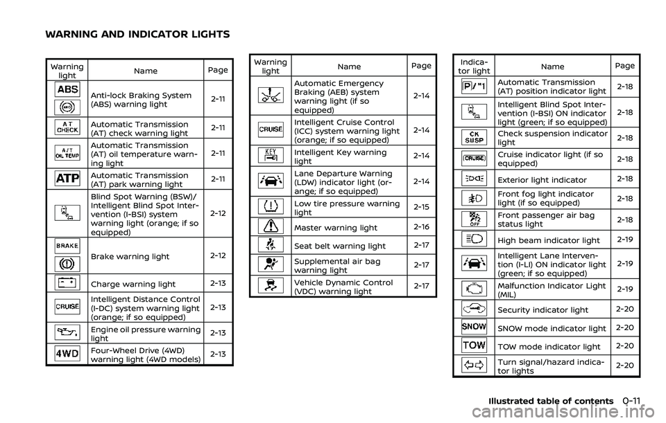
Warninglight Name
Page
Anti-lock Braking System
(ABS) warning light 2-11
Automatic Transmission
(AT) check warning light2-11
Automatic Transmission
(AT) oil temperature warn-
ing light2-11
Automatic Transmission
(AT) park warning light
2-11
Blind Spot Warning (BSW)/
Intelligent Blind Spot Inter-
vention (I-BSI) system
warning light (orange; if so
equipped)2-12
Brake warning light
2-12
Charge warning light2-13
Intelligent Distance Control
(I-DC) system warning light
(orange; if so equipped)2-13
Engine oil pressure warning
light
2-13
Four-Wheel Drive (4WD)
warning light (4WD models)
2-13Warning
light Name
Page
Automatic Emergency
Braking (AEB) system
warning light (if so
equipped) 2-14
Intelligent Cruise Control
(ICC) system warning light
(orange; if so equipped)
2-14
Intelligent Key warning
light
2-14
Lane Departure Warning
(LDW) indicator light (or-
ange; if so equipped)2-14
Low tire pressure warning
light
2-15
Master warning light
2-16
Seat belt warning light 2-17
Supplemental air bag
warning light2-17
Vehicle Dynamic Control
(VDC) warning light
2-17Indica-
tor light Name
Page
Automatic Transmission
(AT) position indicator light 2-18
Intelligent Blind Spot Inter-
vention (I-BSI) ON indicator
light (green; if so equipped)2-18
Check suspension indicator
light
2-18
Cruise indicator light (if so
equipped)2-18
Exterior light indicator
2-18
Front fog light indicator
light (if so equipped)2-18
Front passenger air bag
status light
2-18
High beam indicator light
2-19
Intelligent Lane Interven-
tion (I-LI) ON indicator light
(green; if so equipped)2-19
Malfunction Indicator Light
(MIL)
2-19
Security indicator light
2-20
SNOW mode indicator light2-20
TOW mode indicator light2-20
Turn signal/hazard indica-
tor lights2-20
Illustrated table of contents0-11
WARNING AND INDICATOR LIGHTS
Page 87 of 532
1-66Safety — seats, seat belts and supplemental restraint system
tions that may be interfering with the
weight sensors:
.Small adult or child is not sitting
upright, leaning against the seatback,
and centered on the seat cushion with
his/her feet comfortably extended to
the floor.
. The child restraint is not properly
installed, as outlined. (See “Child re-
straints” (P.1-32).)
. An object weighing over 9.1 lbs (4 kg)
hanging on the seat or placed in the
seatback pocket.
. A child restraint or other object press-
ing against the rear of the seatback.
. A rear passenger pushing or pulling
on the back of the front passenger
seat.
. Forcing the front seat or seatback
against an object on the seat or floor
behind it.
. An object placed under the front
passenger seat.
. An object placed between the seat
cushion and center console.
If the vehicle is moving, please come to a
stop when it is safe to do so. Check and
correct any of the above conditions.
Restart the vehicle and wait 1 minute. NOTE:
A system check will be performed dur-
ing which the front passenger air bag
status light will remain lit for about 7
seconds initially.
If the light is still OFF after this, the small
adult, child or child restraint should be
repositioned in the rear seat and it is
recommended that the vehicle be
checked by a NISSAN dealer as soon as
possible.
Other supplemental front-impact
air bag precautions
WARNING
.
Do not place any objects on the
steering wheel pad or on the
instrument panel. Also, do not
place any objects between any
occupant and the steering wheel
or instrument panel. Such objects
may become dangerous projec-
tiles and cause injury if the front
air bags inflate.
. Do not place objects with sharp
edges on the seat. Also, do not
place heavy objects on the seat
that will leave permanent impres-
sions in the seat. Such objects
can damage the seat or occupant classification sensors (weight
sensors). This can affect the op-
eration of the air bag system and
result in serious personal injury.
. Do not use water or acidic clea-
ners (hot steam cleaners) on the
seat. This can damage the seat or
occupant classification sensors.
This can also affect the operation
of the air bag system and result in
serious personal injury.
. Immediately after inflation, sev-
eral front air bag system compo-
nents will be hot. Do not touch
them; you may severely burn
yourself.
. No unauthorized changes should
be made to any components or
wiring of the supplemental air
bag system. This is to prevent
accidental inflation of the supple-
mental air bag or damage to the
supplemental air bag system.
. Do not make unauthorized
changes to your vehicle’s electri-
cal system, suspension system or
front end structure. This could
affect proper operation of the
front air bag system.
. Tampering with the air bag sys-
tem may result in serious perso-
Page 90 of 532
WARNING
.Do not place any objects near the
seatback of the front seats. Also,
do not place any objects (an
umbrella, bag, etc.) between the
front door finisher and the front
seat. Such objects may become
dangerous projectiles and cause
injury if side air bag inflates.
. Right after inflation, several side
air bags and curtain air bag sys-
tem components will be hot. Do
not touch them; you may severely
burn yourself.
. No unauthorized changes should
be made to any components or
wiring of side air bag and curtain
air bags. This is to prevent da-
mage to or accidental inflation of
the side air bag and curtain air
bag systems.
. Do not make unauthorized
changes to your vehicle’s electri-
cal system, suspension system or
side panel. This could affect prop-
er operation of the side air bag
and curtain air bag systems.
. Tampering with the air bag sys-
tem may result in serious perso- nal injury. For example, do not
change the front seats by placing
material near the seatback or by
installing additional trim materi-
al, such as seat covers, around
the side air bags.
. Removing or modifying the front
passenger seat may affect the
function of the air bag system
and result in serious personal
injury.
. It is recommended you visit a
NISSAN dealer for work on and
around the side air bag and
curtain air bag. It is also recom-
mended you visit a NISSAN dealer
for installation of electrical equip-
ment. The Supplemental Re-
straint System (SRS) wiring
harnesses* should not be modi-
fied or disconnected. Unauthor-
ized electrical test equipment
and probing devices should not
be used on the side-impact air
bag system.
* The SRS wiring harness connectors are
yellow and orange for easy identifica-
tion.
When selling your vehicle, we request that
you inform the buyer about the side air
bag and curtain air bag systems and guide the buyer to the appropriate sec-
tions in this Owner’s Manual.
SEAT BELTS WITH PRETENSIONERS
(front seats)
WARNING
.
The pretensioners cannot be re-
used after activation. They must
be replaced together with the
retractor and buckle as a unit.
. If the vehicle becomes involved in
a collision but a pretensioner is
not activated, be sure to have the
pretensioner system checked
and, if necessary, replaced. It is
recommended you visit a NISSAN
dealer for this service.
. No unauthorized changes should
be made to any components or
wiring of the pretensioner sys-
tem. This is to prevent damage to
or accidental activation of the
pretensioners. Tampering with
the pretensioner system may re-
sult in serious personal injury.
. It is recommended you visit a
NISSAN dealer for work on and
around the pretensioner system.
It is also recommended you visit a
NISSAN dealer for installation of
Safety — seats, seat belts and supplemental restraint system1-69
Page 103 of 532
2-10Instruments and controls
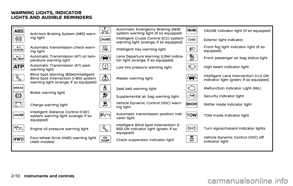
Anti-lock Braking System (ABS) warn-
ing lightAutomatic Emergency Braking (AEB)
system warning light (if so equipped)CRUISE indicator light (if so equipped)
Intelligent Cruise Control (ICC) system
warning light (orange; if so equipped)Exterior light indicator
Automatic transmission check warn-
ing lightIntelligent Key warning lightFront fog light indicator light (if so
equipped)
Automatic Transmission (AT) oil tem-
perature warning lightLane Departure Warning (LDW) indica-
tor light (orange; if so equipped)Front passenger air bag status light
Automatic Transmission (AT) park
warning lightLow tire pressure warning lightHigh beam indicator light
Blind Spot Warning (BSW)/Intelligent
Blind Spot Intervention (I-BSI) system
warning light (orange; if so equipped)Master warning lightIntelligent Lane Intervention (I-LI) ON
indicator light (green; if so equipped)
Brake warning lightSeat belt warning lightMalfunction Indicator Light (MIL)
Supplemental air bag warning lightSecurity indicator light
Charge warning lightVehicle Dynamic Control (VDC) warn-
ing lightSNOW mode indicator light
Intelligent Distance Control (I-DC)
system warning light (orange; if so
equipped)Automatic transmission position indi-
cator lightTOW mode indicator light
Engine oil pressure warning lightIntelligent Blind Spot Intervention (I-
BSI) ON indicator light (green; if so
equipped)Turn signal/hazard indicator lights
Four-Wheel Drive (4WD) warning light
(4WD models)Check suspension indicator lightVehicle Dynamic Control (VDC) off
indicator light
WARNING LIGHTS, INDICATOR
LIGHTS AND AUDIBLE REMINDERS
Page 111 of 532
2-18Instruments and controls
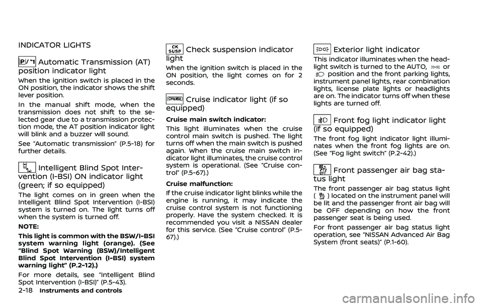
INDICATOR LIGHTS
Automatic Transmission (AT)
position indicator light
When the ignition switch is placed in the
ON position, the indicator shows the shift
lever position.
In the manual shift mode, when the
transmission does not shift to the se-
lected gear due to a transmission protec-
tion mode, the AT position indicator light
will blink and a buzzer will sound.
See “Automatic transmission” (P.5-18) for
further details.
Intelligent Blind Spot Inter-
vention (I-BSI) ON indicator light
(green; if so equipped)
The light comes on in green when the
Intelligent Blind Spot Intervention (I-BSI)
system is turned on. The light turns off
when the system is turned off.
NOTE:
This light is common with the BSW/I-BSI
system warning light (orange). (See
“Blind Spot Warning (BSW)/Intelligent
Blind Spot Intervention (I-BSI) system
warning light” (P.2-12).)
For more details, see “Intelligent Blind
Spot Intervention (I-BSI)” (P.5-43).
Check suspension indicator
light
When the ignition switch is placed in the
ON position, the light comes on for 2
seconds.
Cruise indicator light (if so
equipped)
Cruise main switch indicator:
This light illuminates when the cruise
control main switch is pushed. The light
turns off when the main switch is pushed
again. When the cruise main switch in-
dicator light illuminates, the cruise control
system is operational. (See “Cruise con-
trol” (P.5-67).)
Cruise malfunction:
If the cruise indicator light blinks while the
engine is running, it may indicate the
cruise control system is not functioning
properly. Have the system checked. It is
recommended you visit a NISSAN dealer
for this service. (See “Cruise control” (P.5-
67).)
Exterior light indicator
This indicator illuminates when the head-
light switch is turned to the AUTO,orposition and the front parking lights,
instrument panel lights, rear combination
lights, license plate lights or headlights
are on. The indicator turns off when these
lights are turned off.
Front fog light indicator light
(if so equipped)
The front fog light indicator light illumi-
nates when the front fog lights are on.
(See “Fog light switch” (P.2-42).)
Front passenger air bag sta-
tus light
The front passenger air bag status light
() located on the instrument panel will
be lit and the passenger front air bag will
be OFF depending on how the front
passenger seat is being used.
For front passenger air bag status light
operation, see “NISSAN Advanced Air Bag
System (front seats)” (P.1-60).
Page 284 of 532
![NISSAN ARMADA 2018 Owner´s Manual JVS1043X
HOW TO ENABLE/DISABLE THE I-LI
SYSTEM
Perform the following steps to enable the
I-LI system.
1. Push the SETTING button
.
2. Touch [Driver Assistance].
3. Touch [Lane Assist].
4. Touch [Lane NISSAN ARMADA 2018 Owner´s Manual JVS1043X
HOW TO ENABLE/DISABLE THE I-LI
SYSTEM
Perform the following steps to enable the
I-LI system.
1. Push the SETTING button
.
2. Touch [Driver Assistance].
3. Touch [Lane Assist].
4. Touch [Lane](/img/5/40302/w960_40302-283.png)
JVS1043X
HOW TO ENABLE/DISABLE THE I-LI
SYSTEM
Perform the following steps to enable the
I-LI system.
1. Push the SETTING button
.
2. Touch [Driver Assistance].
3. Touch [Lane Assist].
4. Touch [Lane Departure Prevention] to turn the system ON/OFF.
LDW/I-LI SYSTEM LIMITATIONS
WARNING
Listed below are the system limita-
tions for the LDW and I-LI systems.
Failure to operate the vehicle in
accordance with these system lim-
itations could result in serious injury
or death.
.The system will not operate at
speeds below 45 MPH (70 km/h)
or if it cannot detect lane mar-
kers.
. The I-LI system is primarily in-
tended for use on well-developed
freeways or highways. It may not
detect the lane markers in certain
roads, weather or driving condi-
tions.
. Do not use the I-LI system under
the following conditions as it may
not function properly:
— During bad weather (rain, fog,
snow, etc.).
— When driving on slippery roads, such as on ice or snow,
etc. — When driving on winding or
uneven roads.
— When there is a lane closure due to road repairs.
— When driving in a makeshift or temporary lane.
— When driving on roads where the lane width is too narrow.
— When driving without normal tire conditions (for example,
tire wear, low tire pressure,
installation of spare tire, tire
chains, non-standard wheels).
— When the vehicle is equipped with non-original brake parts
or suspension parts.
— When towing a trailer or other vehicle.
. The camera may not detect lane
markers in the following situa-
tions and the LDW and I-LI sys-
tems may not operate properly.
— On roads where there are
multiple parallel lane markers,
lane markers that are faded or
not painted clearly, yellow
painted lane markers, non-
standard lane markers, or
lane markers covered with
Starting and driving5-29
Page 304 of 532
painted lane markers; non-
standard lane markers; lane
markers covered with water,
dirt, snow, etc.
— On roads where discontinued lane markers are still detect-
able.
— On roads where there are sharp curves.
— On roads where there are sharply contrasting objects,
such as shadows, snow,
water, wheel ruts, seams or
lines remaining after road re-
pairs.
— On roads where the traveling lane merges or separates.
— When the vehicle’s traveling direction does not align with
the lane markers.
— When traveling close to the vehicle in front of you, which
obstructs the lane camera
unit detection range.
— When rain, snow or dirt ad- heres to the windshield in
front of a lane camera unit.
— When the headlights are not bright due to dirt on the lens or if aiming is not adjusted
properly.
— When strong light enters a lane camera unit. (For exam-
ple: light directly shines on the
front of the vehicle at sunrise
or sunset.)
— When a sudden change in brightness occurs. (For exam-
ple: when the vehicle enters or
exits a tunnel or under a
bridge.)
. Do not use the I-BSI system under
the following conditions because
the system may not function
properly.
— During bad weather. (For ex-
ample: rain, fog, snow, etc.)
— When driving on slippery roads, such as on ice or snow,
etc.
— When driving on winding or uneven roads.
— When there is a lane closure due to road repairs.
— When driving in a makeshift or temporary lane. — When driving on roads where
the lane width is too narrow.
— When driving with a tire that is not within normal tire condi-
tions (for example, tire wear,
low tire pressure, installation
of spare tire, tire chains, non-
standard wheels).
— When the vehicle is equipped with non-original brake parts
or suspension parts.
— When towing a trailer or other vehicle.
. Excessive noise (for example,
audio system volume, open vehi-
cle window) will interfere with the
chime sound, and it may not be
heard.
Starting and driving5-49
Page 320 of 532
— Severe weather
— Road spray
— Ice/frost/dirt build up on thevehicle
. Do not attach stickers (including
transparent material), install ac-
cessories or apply additional
paint near the radar sensors.
These conditions may reduce the
ability of the radar sensors to
detect other vehicles.
. The sonar sensors detect station-
ary objects behind the vehicle.
The sonar sensor may not detect:
— Small or moving objects
— Wedge-shaped objects
— Object close to the bumper
(less than approximately 1 ft
(30 cm))
— Thin objects such as rope, wire and chain, etc.
. The brake engagement by the I-
BI system is not as effective on a
slope as it is on flat ground. When
on a steep slope the system may
not function properly.
. Do not use the I-BI system under
the following conditions because
the system may not function properly.
— When driving with a tire that is
not within normal tire condi-
tions (for example, tire wear,
low tire pressure, installation
of spare tire, tire chains, non-
standard wheels).
— When the vehicle is equipped with non-original brake parts
or suspension parts.
— When towing a trailer or other vehicle.
. Excessive noise (for example,
audio system volume, open vehi-
cle window) will interfere with the
chime sound, and it may not be
heard.
JVS0689X
Vehicle information display
SYSTEM TEMPORARILY UNAVAIL-
ABLE
Under the following conditions, a chime
will sound and “BCI NOT AVAILABLE”
warning message will appear in the
vehicle information display
, and the I-
BI system will be turned off automatically.
. If the vehicle is parked in direct sun-
light under high temperature condi-
tions (over approximately 104°F
(40°C)).
. When side radar blockage is detected.
Turn off the I-BI system and turn it on
again when the above conditions no
longer exist.
Starting and driving5-65
Page 395 of 532
5-140Starting and driving
The Vehicle Dynamic Control (VDC) sys-
tem uses various sensors to monitor
driver inputs and vehicle motion. Under
certain driving conditions, the VDC sys-
tem helps to perform the following func-
tions.
.Controls brake pressure to reduce
wheel slip on one slipping drive wheel
so power is transferred to a non
slipping drive wheel on the same axle.
. Controls brake pressure and engine
output to reduce drive wheel slip
based on vehicle speed (traction con-
trol function).
. Controls brake pressure at individual
wheels and engine output to help the
driver maintain control of the vehicle
in the following conditions:
— understeer (vehicle tends to not
follow the steered path despite
increased steering input)
— oversteer (vehicle tends to spin due to certain road or driving condi-
tions).
The VDC system can help the driver to
maintain control of the vehicle, but it
cannot prevent loss of vehicle control in
all driving situations.
When the VDC system operates, the VDC
warning light
in the instrument panel
flashes so note the following: .
The road may be slippery or the
system may determine some action
is required to help keep the vehicle on
the steered path.
. You may feel a pulsation in the brake
pedal and hear a noise or vibration
from under the hood. This is normal
and indicates that the VDC system is
working properly.
. Adjust your speed and driving to the
road conditions.
If a malfunction occurs in the system, the
VDC warning light
illuminates in the
instrument panel. The VDC system auto-
matically turns off.
The VDC OFF switch is used to turn off the
VDC system. The VDC off indicator
illuminates to indicate the VDC system is
off. When the VDC switch is used to turn
off the system, the VDC system still
operates to prevent one drive wheel from
slipping by transferring power to a non
slipping drive wheel. The VDC warning
light
flashes if this occurs. All other
VDC functions are off, and the VDC
warning light
will not flash. The VDC
system is automatically reset to on when
the ignition switch is placed in the OFF
position then back to the ON position.
When the 4L position is selected with the
4WD shift switch, the VDC system is
disabled and the VDC off indicator light illuminates (for 4WD models).
See “Vehicle Dynamic Control (VDC) warn-
ing light” (P.2-17) and “Vehicle Dynamic
Control (VDC) off indicator light” (P.2-20).
The computer has a built-in diagnostic
feature that tests the system each time
you start the engine and move the vehicle
forward or in reverse at a slow speed.
When the self-test occurs, you may hear a
“clunk” noise and/or feel a pulsation in the
brake pedal. This is normal and is not an
indication of a malfunction.
WARNING
.
The VDC system is designed to
help improve driving stability but
does not prevent accidents due
to abrupt steering operation at
high speeds or by careless or
dangerous driving techniques.
Reduce vehicle speed and be
especially careful when driving
and cornering on slippery sur-
faces and always drive carefully.
. Do not modify the vehicle’s sus-
pension. If suspension parts such
as shock absorbers, struts,
springs, stabilizer bars, bushings
and wheels are not NISSAN re-
commended for your vehicle or
VEHICLE DYNAMIC CONTROL (VDC) SYSTEM
Page 408 of 532
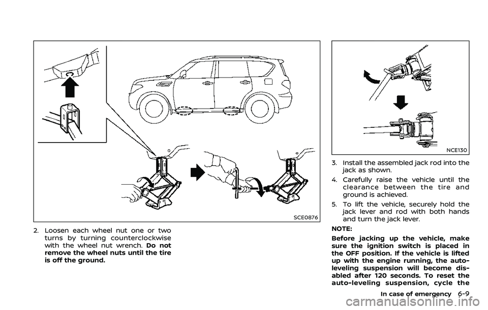
SCE0876
2. Loosen each wheel nut one or twoturns by turning counterclockwise
with the wheel nut wrench. Do not
remove the wheel nuts until the tire
is off the ground.
NCE130
3. Install the assembled jack rod into the
jack as shown.
4. Carefully raise the vehicle until the clearance between the tire and
ground is achieved.
5. To lift the vehicle, securely hold the jack lever and rod with both hands
and turn the jack lever.
NOTE:
Before jacking up the vehicle, make
sure the ignition switch is placed in
the OFF position. If the vehicle is lifted
up with the engine running, the auto-
leveling suspension will become dis-
abled after 120 seconds. To reset the
auto-leveling suspension, cycle the
In case of emergency6-9