brake rotor NISSAN GT-R 1998 Service Manual
[x] Cancel search | Manufacturer: NISSAN, Model Year: 1998, Model line: GT-R, Model: NISSAN GT-R 1998Pages: 230, PDF Size: 12.66 MB
Page 88 of 230
![NISSAN GT-R 1998 Service Manual
ANTI-LOCK BRAKE SYSTEM
CONSULT
(Contd)
SELF-DIAGNOSTIC RESULTS MODE
Diagnostic item I Diagnostic item is detected when ... I Check item
FR RH SENSOR
[OPEN] Circuit
for front right wheel](/img/5/57354/w960_57354-87.png "NISSAN GT-R 1998 Service Manual
ANTI-LOCK BRAKE SYSTEM
CONSULT
(Contd)
SELF-DIAGNOSTIC RESULTS MODE
Diagnostic item I Diagnostic item is detected when ... I Check item
FR RH SENSOR
[OPEN] Circuit
for front right wheel")
ANTI-LOCK BRAKE SYSTEM
CONSULT
(Cont'd)
SELF-DIAGNOSTIC RESULTS MODE
Diagnostic item I Diagnostic item is detected when ... I Check item
FR RH SENSOR
[OPEN] Circuit
for front right wheel sensor is open. Or an abnormally high input voltage is
entered due to short to battery.
FR LH SENSOR
[OPEN]
- -- -- - - - ---
Circuit for front left wheel sensor is open. Or an abnormally high input voltage is entered
due to short to battery.
1
FR RH SENSOR
[SHORTJ'I
, '2
REAR SENSOR
[OPEN] Circuit
for rear wheel sensor is open. Or an abnormally high input voltage is entered due
to short to battery.
1
FR LH SENSOR
[SHORT] Front
right wheel sensor is short-circuited or shorted to ground, or gap between the
wheel sensor and the sensor rotor is large. An abnormally low
input voltage is entered
and input signal is abnormal.
Front left wheel sensor is short-circuited or shorted to ground, or gap between the wheel
sensor and the sensor rotor is large. An abnormally low input voltage is entered and
input signal is abnormal. Wheel
sen-
sor and cir-
cuit
REAR SENSOR
[SHORT
11'1, '2
Rear wheel sensor is short-circuited or shorted to ground, or gap between the wheel
sensor and the sensor rotor is large.
An abnormally low input voltage is entered and
input signal is abnormal.
FR RH IN ABS SOL
[OPEN]
FR LH IN ABS SOL
[OPEN] Circuit
for front right inlet solenoid valve is open, or an output voltage is much lower than
the specified value due to short to ground.
Circuit for front left inlet solenoid valve is open, or an output voltage is much lower than
the specified value due to short to ground.
REAR IN ABS SOL
[OPEN] Circuit
for rear inlet solenoid valve is open, or
an output voltage is much lower than the
specified value due to short to ground.
FR RH IN ABS SOL
[SHORT] Circuit
for front right inlet solenoid valve is shorted, or an output voltage is much higher
than the specified value due to short to battery.
FR LH IN ABS SOL
[SHORT] Circuit for front
left inlet solenoid valve is shorted, or an output voltage is much higher
than the specified value due to short to battery.
REAR IN ABS SOL
[SHORTJ
FR RH OUT ABS SOL
[OPEN]
FR
LH OUT ABS SOL
[OPEN]
REAR OUT ABS SOL
[SHORT]
FR RH OUT ABS SOL
[SHORT]
FR LH OUT ABS SOL
[SHORT]
RWR OUT ABS SOL
[SHORT] Circuit for
rear inlet solenoid valve is shorted, or an output voltage is much higher than
the specified value due to short to battery.
Circuit for front right outlet solenoid valve
is open, or an output voltage is much lower
than the specified value due to short to ground.
Circuit for front left outlet solenoid valve is open, or an output voltage is much lower than
the specified value due to short to ground.
Circuit for rear outlet solenoid valve is open, or an output voltage is much lower than the
specified value due to short to ground.
Circuit for front right outlet solenoid valve
is shorted, or an output voltage is much higher
than the specified value due to short to battery.
Circuit for front left outlet solenoid valve is shorted, or an output voltage is much higher
than the specified value due to short to battery.
- -- -- - - Circuit for rear outlet solenoid valve is shorted, or an output voltage is much higher than
the specified value due to short to battery.
ABS MOTOR
[ON FAILURE]
ABS MOTOR
[OFF FAILURE] ABS
sole-
noid
and cir-
cuit
ABS ACTUATOR RELAY
[ON FAILURE]
ABS ACTUATOR RELAY
[OFF FAILURE] ABS
motor turns ON when control unit sends OFF signal. ABS motor circuit is open or
shorted to ground.
ABS motor turns OFF when control unit sends ON signal. Relay control wire is broken. ABS motor,
motor relay
and circuit
ABS actuator relay tums ON when control unit sends OFF signal. Actuator relay is
short-
circuited to ground.
ABS actuator relay tums OFF when control unit sends ON signal. Relay control wire is
broken. ABS
actuator
relay and
circuit
Page 95 of 230
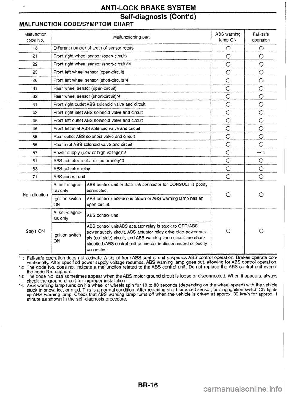
ANTI-LOCK BRAKE SYSTEM
Self-diagnosis (Cont'd)
MALFUNCTION CODEISYMPTOM CHART
Malfunction code No. Malfunctioning
part ABS warning
lamp
ON
Fail-safe
operation
18 1 Different number of teeth of sensor rotors 1010
2 1
26 I Front left wheel sensor (short-circuiQ.4 1010
- --
22
25
3 1 I Rear wheel sensor (open-circuit) 1010
Front right wheel sensor (open-circuit)
32 Rear wheel sensor (short-circuit)'4 1 0 1 0
Front right wheel sensor (short-circuit)'4
Front left wheel sensor (open-circuit)
41
I Front right outlet ABS solenoid valve and circuit 1010
0 0
0
0
0
0
- -
42
-- - -
46 Front left inlet ABS solenoid valve and circuit 0 1 0
45 Front
left outlet ABS solenoid valve and circuit
55
1 Rear outlet ABS solenoid valve and circuit 1010
Front right inlet ABS solenoid valve and circuit
56
1 Rear inlet ABS solenoid valve and circuit 1010
0
57 1 Power supply (Low or high voltage)*2 I 0 I -'I
0
0
0
I At self-diagno- ( ABS control unit or data link connector for CONSULT is poorly 1 I
61
63
At self-diagno-
I ABS control unit
sis only
ABS
actuator motor or motor relayg3
ABS
actuator relay
No indication
I I ABS control unit1ABS actuator relay is stuck to OFFJABS I Stays ON power supply circuit, ABS actuator relay drive side power sup-
lgnition switch
ply (coil side) circuit, and ABS warning lamp circuit are
short-
circuited./ABS control unit connector is disconnected or poorly
0
0
I
sis only
Ignition switch
ON
I I connected. I I
0
0
connected.
ABS control
unit1Fuse is blown or ABS warning lamp has an
open circuit.
- -- '1: Fail-safe operation does not activate. A signal from ABS control unit suspends ABS control operation. Brakes operate con-
ventionally. After specified power supply voltage resumes, ABS warning lamp goes out, allowing for ABS control operation. '2: The code No. does not indicate a malfunction related to the ABS control unit. Do not replace the ABS control unit even if the code No. appears. '3: The code No. can sometimes appear when the ABS motor ground circuit is loose or disconnected. When it appears, always
check the ground circuit for improper installation.
'4: ABS warning lamp turns on if a wheel or wheels spin for 10 to 80 seconds (depending on the wheel speed) with the vehicle
stuck in snow, ice, or mud. This is a normal condition. After repairing short-circuited sensor, turning ignition switch ON lights
up
ABS warning lamp. Check that ABS warning lamp turns off when the vehicle is driven at approx. 30 krnlh for approx. 1 minute as shown in the self-diagnosis procedure.
Page 105 of 230

TCSlABS SYSTEM
Precautions for Trouble
Diagnosis
After performing trouble diagnosis, be sure to erase trouble stored in memory.
Refer to "CONSULT for
TCS/ABS Control Unit Control System"
(BR-27), "Self-diagnosis for TCSIABS
Control Unit Control System"
(BR-34), "CONSULT for Throttle Control Unit Control System" (BR-37) or
"Self-diagnosis for Throttle Control Unit Control System"
(BR-41).
The concerns that are difficult to duplicate may be caused by faulty electrical connections. Move harnesses
or harness connectors by hand to check if there is any poor mating of connector halves or faulty connec-
tion. Do not force to open a connector terminal when using a circuit tester for inspection.
Read GI section thoroughly in advance and make sure of all the general precautions.
Basic Inspection
BASIC INSPECTION 1 - Brake fluid level and leakage
1. Check brake fluid level in reservoir tank. Replenish brake fluid if necessary.
2. Check for leakage at or around brake piping and ABS actuator. If leakage or seepage is noted, proceed
as follows:
If ABS actuator connectors are loose, tighten to specified torque. Recheck to ensure that leakage is no
longer present.
If flare nut threads at piping connectors or actuator threads are damaged, replace faulty parts with new
ones. Recheck to ensure that leakage is no longer present.
If brake fluid leaks through areas other than actuator connectors, wipe off using a clean cloth. Recheck
for leakage or seepage. If necessary, replace faulty parts with new ones.
If brake fluid leaks at or seeps through ABS actuator, wipe off using a clean cloth.
Recheck for leakage or seepage. If necessary, replace ABS actuator with new one.
CAUTION:
ABS actuator cannot be disassembled. Do not attempt to disassemble it.
3. Check brake disc rotors and pads for proper operation.
BASIC INSPECTION 2 - Loose power line terminal
Check battery terminals (positive and negative) and battery mounting (ground) for looseness. If necessary,
tighten to specified torque. Check the battery for lower voltage.
BASIC INSPECTION 3 - SLlP indicator lamp, TCS OFF indicator lamp and ABS warning
lamp
Turn ignition switch "ON" to ensure that TCS OFF indicator lamp lights up. If TCS OFF indicator lamp does
not light, check TCS OFF indicator lamp circuit.
Turn ignition switch
"ON" to ensure that SLlP indicator lamp lights
up. If SLlP indicator lamp does not light,
check SLlP indicator lamp circuit.
Turn ignition switch "ON" to ensure that ABS warning lamp lights up. If ABS warning lamp does not light,
check ABS warning lamp circuit.
Check that the SLlP indicator lamp and the ABS warning lamp go off approx.
1 second after the engine
has started. If either of the lamps still remains on, perform the self-diagnosis for TCSIABS control unit
control system and the self-diagnosis for throttle control unit control system.
After driving vehicle at approx. 30
km/h
for approx.
1 minute, check to ensure that the SLlP indicator lamp
and the ABS warning lamp are off. If either of the lamps still remains on, perform the self-diagnosis for
TCS/ABS
control unit control system and the self-diagnosis for throttle control unit control system.
Check that the TCS OFF indicator lamp turns ON and OFF when the TCS OFF switch is turned to
ON
and OFF respectively, with the engine running. If the lamp status does not correspond to the switch
position, check the TCS OFF switch circuit.
Check that the TCS OFF indicator lamp goes off when the engine has started with the TCS OFF switch
OFF. If the TCS
OFF indicator lamp does not go off even 10 seconds after the engine has started, per-
form the self-diagnosis for TCSIABS control unit control system and the self-diagnosis for throttle control
unit control system.
After driving vehicle at approx.
30 kmlh for approx. 1 minute with the TCS OFF switch OFF, check to ensure
that the TCS OFF indicator lamp is off. If the TCS OFF indicator lamp lights up, perform the
self-diagno-
sis for
TCS/ABS
control unit control system and the self-diagnosis for throttle control unit control system.
After performing self-diagnosis procedures, be sure to erase trouble stored in memory.
Page 228 of 230

BRAKE
BRAKING FORCE
More than 10% of axle
weight
REAR DlSC BRAKE
Total braking force of rear wheels
Variation between right and left of
each wheel Brake
type
Less than 8% of axle weight ADllVC
9.3
Brake
pad
Disc rotor
Total
braking force OPZ11V
11.5
Standard
thickness (New) mm
Wear limit of thickness mm
Standard thickness (New) mm
Wear limit of thickness mm
Runout limit mm
More than 50%
of vehicle
weight at inspected
Note: The braking force when both front wheels are locked up can be considered to meet the total braking force.
2.0
16
14
BRAKE PEDAL
18
16
PARKING BRAKE
Free play (at pedal top surface)
mm I 3 - 11 Less than
0.07 Type DS17HD I
Brake
lining
Depressed pedal height under force
of 490 N (50 kg)
(from dash panel top surface)
mm
Brake
pedal height
(from dash panel top surface)
mm
Standard inner diameter
I (New) mm I
Standard thickness (New) mrn
Wear limit of thickness
mm M/T: 163 - 173 IVT: 170 - 180
172 dia. 3.0 1.5
M/T: More
than 85 A. More than 90 . . Drum I
I
Wear limit of inner diameter
mm I 173 dia.
Clearance between the edge of stop
lamp switch screw and pedal stopper
mm Operating
stroke
[under force of 196 N (20
kg)] 5 - 7 notches
CHECK VALVE I
I
Maximum stroke
19 notches
Number of notches when brake warning
lamp turns on
TIGHTENING TORQUE
Unit: N.m (kg-m)
Within 1 notch
Vacuum leakage
[at
vacuum Of 66'7 kPa (-500 mmHg)]
BRAKE BOOSTER
Within 1.3 kPa (10 mmHg) of
vacuum for 15 seconds
Master cylinder fixing nut
I 12 - 14 (1.2 - 1.5)
Vacuum leakage
[at vacuum of 66.7
kPa
(-500
mmHg)l
Within 3.3
kPa
(25
mmHg)
of
vacuum for 15 seconds Front
caliper mounting bolt
Brake tube flare nut -- - 152 - 154 (15.5 - 15.8)
15
- 17 (1.5 - 1.8)
FRONT DlSC BRAKE
Input rod standard length at installed
mm
Brake type
I AD25VB I CUSVD [OPZ~~VC
140
Standard thickness
Wear limit of
thickness
Standard thickness
mm
1 22 1 26 1 30
Disc rotor Wear limit of
thickness
Runout
limit Less than 0.07