bulb NISSAN GT-R 1998 Service Manual
[x] Cancel search | Manufacturer: NISSAN, Model Year: 1998, Model line: GT-R, Model: NISSAN GT-R 1998Pages: 230, PDF Size: 12.66 MB
Page 24 of 230

TROUBLE DIAGNOSES
Self-diagnosis (Cont'd)
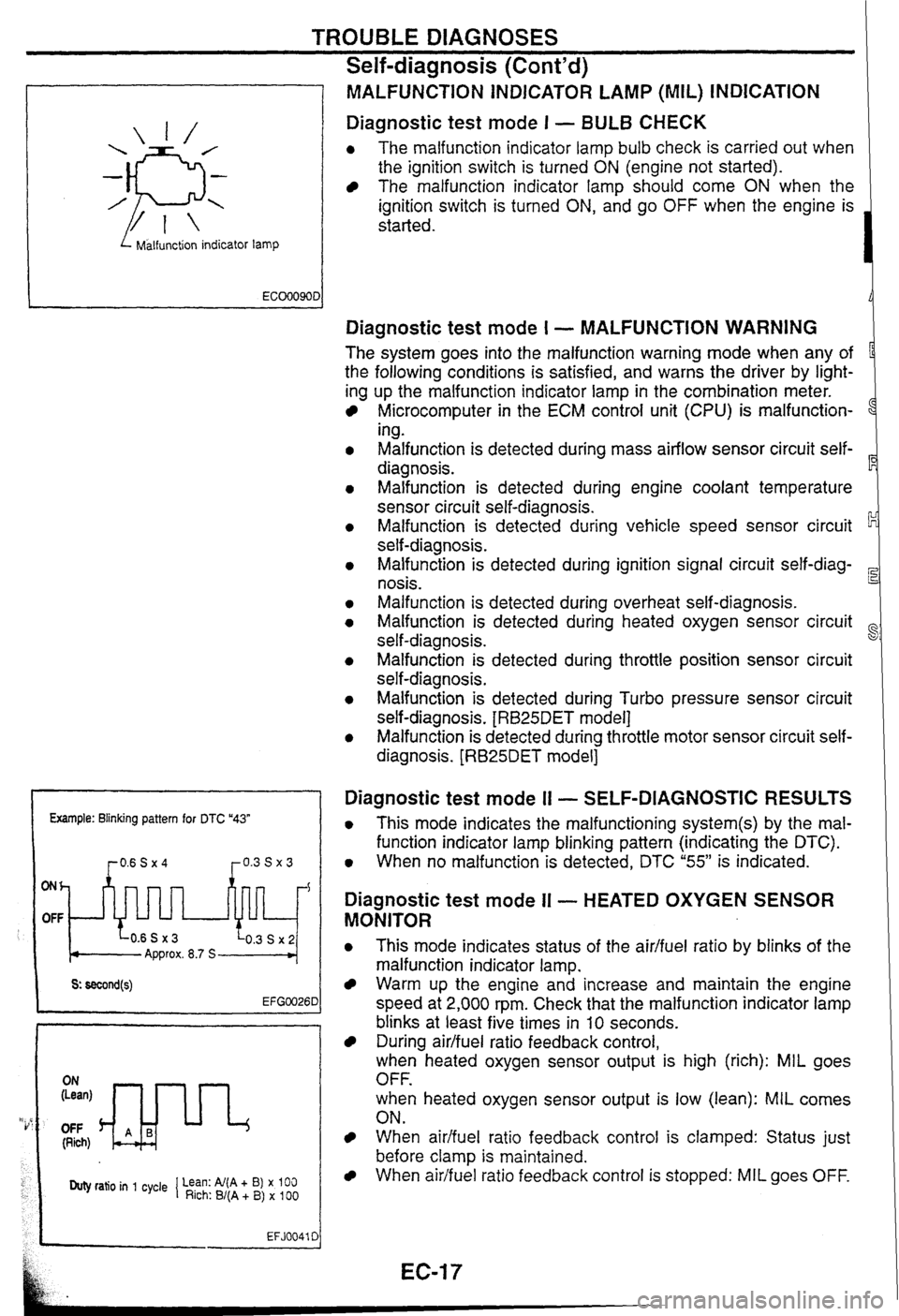
I Malfunction indicator lamp
MALFUNCTiON INDICATOR LAMP (MIL) INDICATION
Diagnostic test mode I - BULB CHECK
0 The malfunction indicator lamp bulb check is carried out when
the ignition switch is turned
ON (engine not started).
The malfunction indicator lamp should come ON when the
ignition switch is turned
ON, and go OFF when the engine is
started.
Example: Blinking pattern for DTC "43"
ONh
OFF
Approx. 8.7 S
OFF (Rich)
Duty ratio in 1 cycle 1 Lean: Al(A + B) x 100 Rich: B/(A + B) x 100
EFJ0041 C
Diagnostic test mode I - MALFUNCTION WARNING
The system goes into the malfunction warning mode when any of
the following conditions is satisfied, and warns the driver by light-
ing up the malfunction indicator lamp in the combination meter.
Microcomputer in the ECM control unit (CPU) is malfunction-
1
ing.
Malfunction is detected during mass airflow sensor circuit self-
diagnosis.
Malfunction is detected during engine coolant temperature
sensor circuit self-diagnosis.
Malfunction is detected during vehicle speed sensor circuit
self-diagnosis.
Malfunction is detected during ignition signal circuit
self-diag-
nosis.
Malfunction is detected during overheat self-diagnosis.
Malfunction is detected during heated oxygen sensor circuit
self-diagnosis.
~alfunsion is detected during throttle position sensor circuit
self-diagnosis.
Malfunction is detected during Turbo pressure sensor circuit
self-diagnosis.
[RB25DET model]
Malfunction is detected during throttle motor sensor circuit self-
diagnosis.
[RB25DET model]
Diagnostic test mode I1 - SELF-DIAGNOSTIC RESULTS
0 This mode indicates the malfunctioning system(s) by the mal-
function indicator lamp blinking pattern (indicating the DTC).
0 When no malfunction is detected, DTC "55" is indicated.
Diagnostic test mode II - HEATED OXYGEN SENSOR
MONITOR
0 This mode indicates status of the aidfuel ratio by blinks of the
malfunction indicator lamp.
Warm up the engine and increase and maintain the engine
speed at 2,000 rpm. Check that the malfunction indicator lamp
blinks at least five times in
10 seconds.
During airlfuel ratio feedback control,
when heated oxygen sensor output is high (rich): MIL goes
OFF.
when heated oxygen sensor output is low (lean):
MIL comes
ON.
When aidfuel ratio feedback control is clamped: Status just
before clamp
is maintained.
When airifuel ratio feedback control is stopped: MIL goes OFF.
Page 154 of 230

FULLY AUTOMATIC AIR CONDITIONER
Performance Test
PROCEDURE
Connect the manifold gauge to the vehicle side cooler cycle (service valve).
Attach a psychrometer to the recirculation air inlet port of the blower and cooling unit (below the glove box);
and attach a dry-bulb thermometer to the right side of the center ventilator grille.
Start and
warm up the engine.
After warming up the engine, check that the engine speed has reached the standard idle speed.
After pressing the AUTO switch, operate the fan switch, mode switch (air outlet switch),
REG switch, tem-
perature adjustment dial and switch; and satisfy the following conditions.
Fan speed: 4th
Air inlet: Recirculation
Air outlet: Ventilator (VENT)
Temperature setting:
18°C
Completely open the hood and all door windows, and close all doors.
Maintain these conditions until the cooler cycle stabilizes. (Approx.
10 minutes)
Maintain the engine speed at idle.
Measure the recirculation inlet temperature and humidity, outlet temperature, and cooler cycle high- and
low-pressures. Compare and judge the values with the "AMBIENT AIR TEMPERATURE AND PRESSURE
CHARACTERISTICS and "INTAKE AIR TEMPERATURE AND DISCHARGE AIR TEMPERATURE CHAR-
ACTERISTICS.
Page 180 of 230

XENON HEADLAMP SYSTEM
Trouble Diagnoses
DESCRIPTION
Problems with xenon headlamps are as follows:
They do not light up.
They blink.
GD
They are not bright enough.
In most cases the problems above are caused by faulty xenon bulbs.
There might be the possibility that the problems are caused by faulty HID control unit or lamp sockets.
ec
Follow the diagnostic procedure to determine what causes the problem.
PRECAUTIONS AT
Connect or disconnect connectors with the lighting switch OFF.
Do not touch harnesses, HID control unit, internal lamp, or metal part of the lamp while the lamps are
ON B2
(Lighting switch is ON).
Before verifying that the lamps are ON, install the parts to the vehicle temporarily and connect the battery
cable with
the connector on the vehicle. ST
If the electrical system is suspected to be the cause of the symptom, check for blown fuse or fusible link,
broken connectors, disconnected terminals, or faulty engagement.
Do not use wet hands when performing the trouble diagnoses.
F@
CIRCUIT DIAGRAM
, MA Xenon
headlamp
relay
To clearance
JJ$Rkj
lamp and
tail lamp
Headlamp
1 -- - -1 : High-voltage parts
Driver door SM
CAUTION:
0 Do not use a tester to diagnose the HID control unit circuit.
0 Do not disassemble the HID control unit and harnesses (bulb socket harness and control unit har-
ness).
0 Immediately after the headlamps turn ON, brightness and emission color vary. This is a normal
condition.
When a bulb has reached the end of its life, the brightness becomes extremely low, the bulb con-
tinues to blink, or the light looks reddish.
Page 181 of 230

XENON HEADLAMP SYSTEM
Trouble Diagnoses (Cont'd)
DIAGNOSTIC PROCEDURE
I
FUSE, FUSIBLE LINK, AND XENON Fuse, fusible link, or xenon
HEADLAMP RELAY CHECK headlamp relay is faulty.
CONNECTOR CHECK ON THE VEHICLE Harness on the vehicle is
FOR BATTERY VOLTAGE faulty.
With lighting switch ON, check HID control
unit connector on the vehicle for battery
I voltage. I
OK
XENON HEADLAMP BULB REPLACE- Xenon bulb is faulty.
MENT
Replace the xenon headiamp bulb with a
known
good bulb and check for proper
operation.
HID CONTROL UNIT REPLACEMENT HID control unit is faulty.
Install a known good
HID control unit to
I
the xenon headlarnp and check for proper
operation.
NG
XENON HEADLAMP HOUSING ASSEM- OK, BLY REPLACEMENT
Install a known good xenon headlamp
housing assembly to the xenon
headlamp
and check for proper operation.
---
Starter in xenon headlamp
housing (boost circuit) is
faulty. (Xenon
headlamp housing
assembly
is faulty.)
Page 183 of 230

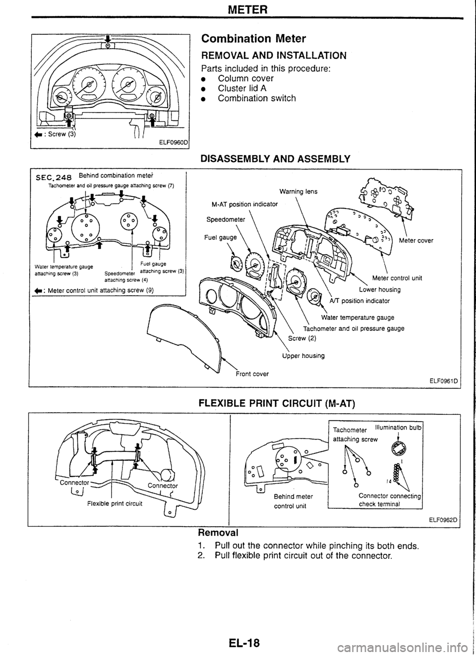
METER
Combination Meter
REMOVAL AND INSTALLATION
Parts included in this procedure:
Column cover
Cluster lid A
Combination switch
-
DISASSEMBLY AND ASSEMBLY
s EC, 248 Behind combination mete! I Tachometer and oil pressure gauge anaching screw (7)
Water tem~erature cauae I "GI yauyc - .. attaching screw (3) speedornet&
position indicator
ater temperature gauge
Tachometer
and oil pressure gauge
. . anaching screw (4)
C: Meter control unit attaching screw (9)
Upper housing cover
lit
FLEXIBLE PRINT CIRCUIT (M-AT)
I I
- Flexible
print circuit 7 r,
Tachometer Illumination bulb I
Behind meter Connector connecting
control unit
I check terminal I
I
Removal
1. Pull out the connector while pinching its both ends.
2. Pull flexible print circuit out of the connector.
Page 184 of 230

METER
Combination Meter (Cont'd)
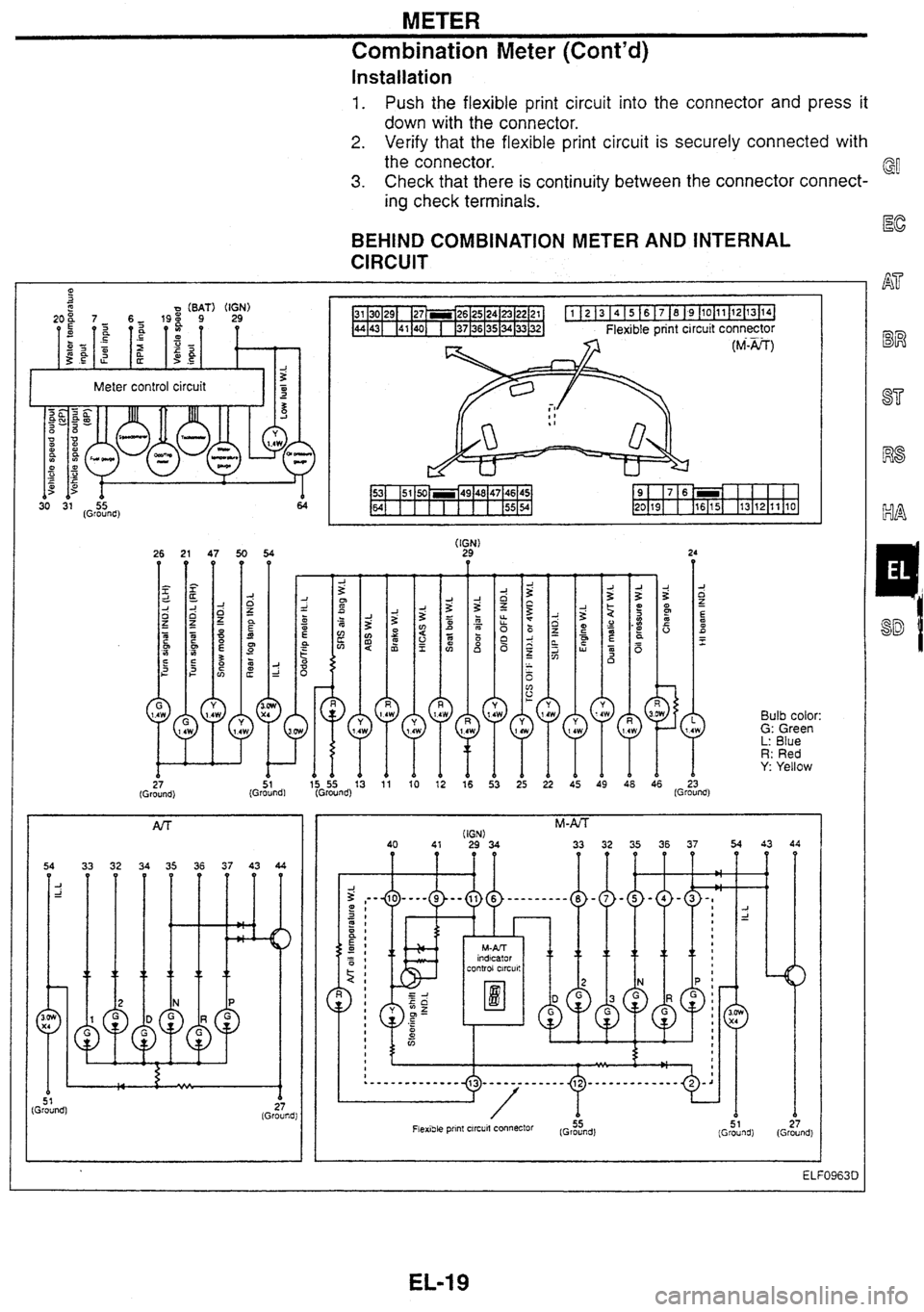
Installation
1. Push the flexible print circuit into the connector and press it
down with the connector.
2. Verify that the flexible print circuit is securely connected with
the connector.
3. Check that there is continuity between the connector connect-
ing check terminals.
BEHIND COMBINATION METER AND INTERNAL
CIRCUIT
1 27 (Ground)
2 x
z g2
15 55 13 (Ground)
1 51 (Ground)
5 1 Ground) z I (Ground!
Bulb color: G: Green L: Blue R: Red Y: Yellow
51 27 (Ground)
(Ground)
Page 188 of 230

COMBINATION METER
Trouble
Diagnoses
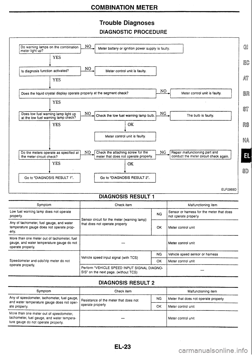
DIAGNOSTIC PROCEDURE
I YES
Meter control unit is faulty.
Meter battery or ignition power supply is faulty.
DO
warning
lamps
on
the
meter light
up?
. No .
at the low fuel warning lamp check? The bulb
is faulty.
t
Meter control unit is faulty. I
Does the liquid crystal display operate properly at the segment check? NO
Check the attaching screw for the ' NG *F3epair malfunct~oning part and
the meter circuit check? meter that
does not operate properly. * conduct the meter circuit check again.
OK
Meter control unit is faulty.
YES
DIAGNOSIS RESULT 1
4
Symptom I Check item I Malfunctioning item
Go
to "DIAGNOSIS RESULT
1".
Low fuel warning lamp does not operate
properly. Go to
"DIAGNOSIS RESULT
2".
Any of tachometer, fuel gauge, and water
temperature gauge does not operate prop-
erly.
More than one meter out of tachometer, fuel
gauge, and water temperature gauge do not
operate properly.
Speedometer and
odohrip meter do not
operate properly. Sensor
or harness for the meter that does
Sensor circuit for the meter (warning lamp)
1 1: 1 not operate properiy
1 that does not operate properly
~ Meter control unit
Meter control unit
DIAGNOSIS RESULT 2
Symptom
Any of speedometer, tachometer, fuel gauge,
and water temperature gauge does not oper-
ate properly. Vehicle
speed sensor or harness
Meter control unit
-
Vehicle speed input signal (with TCS)
Check item
I Malfunctioning item
NG
OK
Perform "VEHICLE SPEED INPUT SIGNAL
DIAGNO-
SIS"
on the next page. (without TCS)
More than one meter out of speedometer,
tachometer, fuel gauge, and water tempera-
ture gauge
do not operate properly. Resistance
of the meter that does not
operate properly
Meter control unit
NG
OK
- -
Meter that does not operate properly
Meter control unit