catalytic converter NISSAN GT-R 1998 Service Manual
[x] Cancel search | Manufacturer: NISSAN, Model Year: 1998, Model line: GT-R, Model: NISSAN GT-R 1998Pages: 230, PDF Size: 12.66 MB
Page 40 of 230

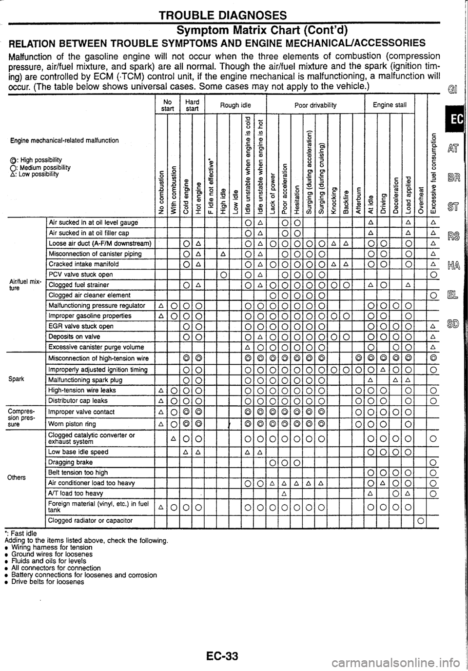
TROUBLE DIAGNOSES
Symptom Matrix Chart (Cont'd)
RELATION BETWEEN TROUBLE SYMPTOMS AND ENGINE MECHANICAUACCESSORIES
Malfunction of the gasoline engine will not occur when the three elements of combustion (compression
pressure, aidfuel mixture, and spark) are all normal. Though the
aidfuel mixture and the spark (ignition tim-
ing) are controlled by ECM
(.TCM) control unit, if the engine mechanical is malfunctioning,
a malfunction will
occur. (The table below shows universal cases. Some cases may not apply to the vehicle.)
Engine mechanical-related malfunction
0: High possibility 0: Medium possibility A: Low posstbility
I No I Hard
start start
I Air sucked in at oil level gauge
Air sucked in at oil filler cap
Loose air duct
(A-F/M downstream) 0 A
Misconnection of canister piping
0 A
Cracked intake manifold
0 A
Aidfuel
mix-
ture
PCV valve stuck open
Clogged fuel strainer
0 A
Clogged air cleaner element
Malfunctioning pressure regulator
A 0 0 0
Improper gasoline properties A000
EGR valve stuck open 0 0
Deposits on valve 0 0
Excessive canister purge volume
Misconnection of high-tension wire
Improperly adjusted ignition timing
Malfunctioning spark plug
High-tension wire leaks
A000
Spark Distributor cap leaks
A000
Compres-
Improper valve contact
sion pres-
. a080
sure Worn piston ring ~080
Others
Clogged catalytic converter or
exhaust system A00
Low base idle speed A
A
Foreign material (vinyl, etc.) in fuel 1 tank
Clogged radiator or capacitor
IIII
Rough idle I Poor drivability Engine stall
- - - - - - -- ': Fast
idle
Adding to the items listed above, check the following.
Wiring harness for tension Ground wires for loosenes nuids and oils for levels All connectors for connection Battery connections for loosenes and corrosion Drive belts for loosenes
Page 41 of 230

TROUBLE DIAGNOSES
Symptom Matrix Chart (Cont'd)
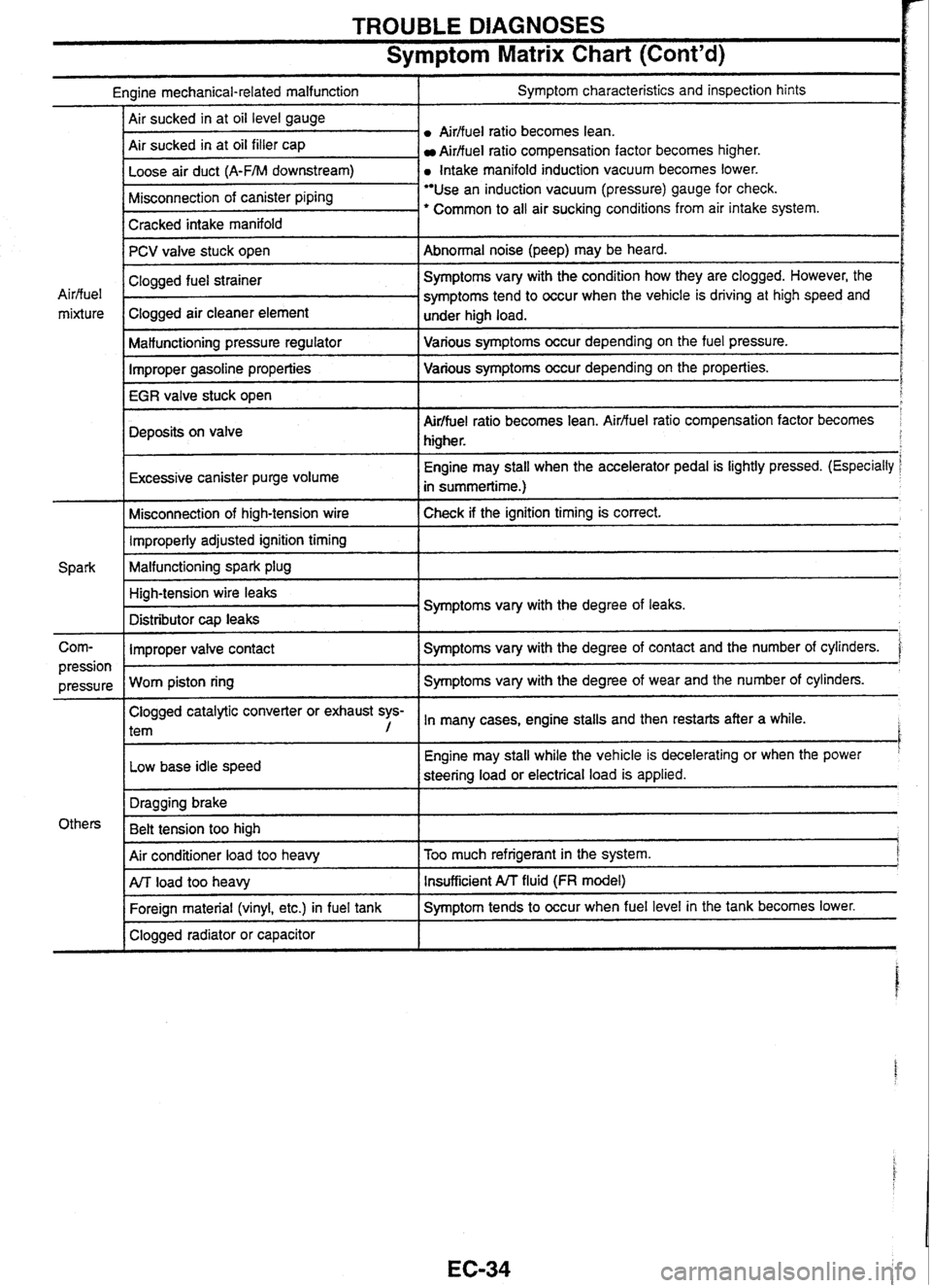
Engine mechanical-related malfunction I Symptom characteristics and inspection hints
Airffuel
ratio becomes lean.
Air sucked in at oil filler cap
Aidfuel ratio compensation factor becomes higher.
a Intake manifold induction vacuum becomes lower.
I Cracked intake manifold I
Misconnection of canister piping Use an induction vacuum (pressure) gauge for check.
' Common to all air sucking conditions from air intake system.
-
PCV valve stuck open
I Malfunctioning pressure regulator I Various symptoms occur depending on the fuel pressure.
Abnormal noise (peep) may
be heard.
Air/fuel
mixture
Improper gasoline properties Various
symptoms occur depending on the properties.
IEGRiale
stuck open
I
Clogged fuel strainer .
Clogged air cleaner element
Deposits on valve
r
Symptoms vary with the condition how they are clogged. However, the
symptoms tend to occur when the vehicle is driving at high speed and
under high load.
I
Air/fuel ratio becomes lean. Airfluel ratio compensation factor becomes
higher.
Excessive canister purge volume
I
Engine may stall when the accelerator pedal is lightly pressed. (Especially
in summertime.)
Misconnection of high-tension wire Check if the ignition timing
is correct. 1 Improperly adjusted ignition timing 1
Malfunctioning spark plug 1
Corn- I Improper valve contact I Symptoms vary with the degree of contact and the number of cylinders. '
High-tension wire leaks
Distributor
cap leaks Symptoms
vary with the degree of leaks.
Clogged catalytic converter or exhaust sys-
l tem , In many cases, engine stalls and then restarts after a while. I
pression I
Low base idle speed
pressure
Worn piston ring I
Engine may
stall while the vehicle is decelerating or when the power '
steering load or electrical load is applied.
Symptoms vary
with the degree of wear and the number of cylinders.
I
Air conditioner load too heavy I Too much refrigerant in the system. j
Others Dragging
brake
Belt tension too high
1
I Clogged radiator or capacitor I
ArJ load too heavy
Foreign material (vinyl, etc.) in fuel tank Insufficient A/T fluid (FR model)
Symptom tends to occur when fuel level in the tank becomes lower.
Page 203 of 230

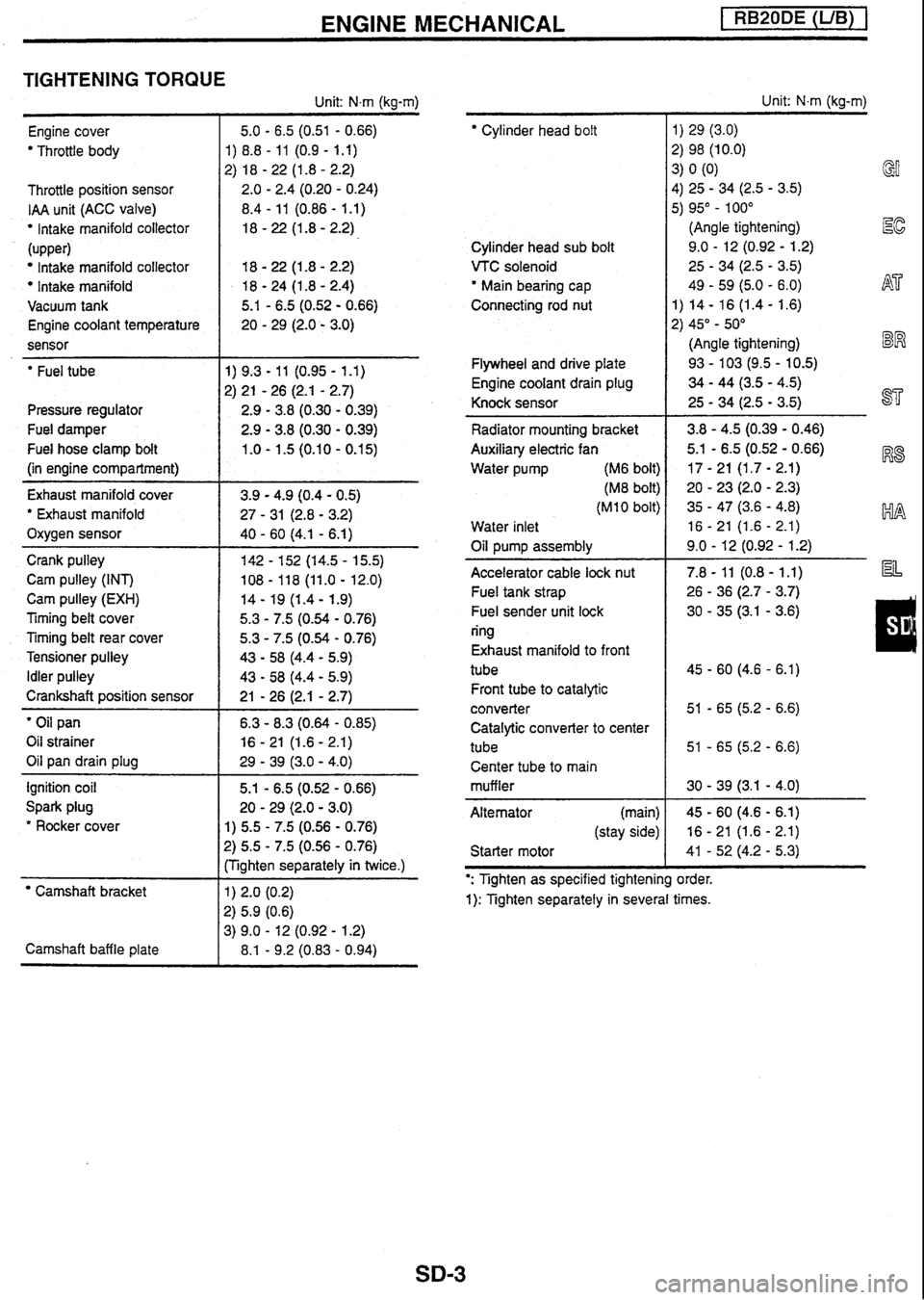
ENGINE MECHANICAL [ RB20DE (UB) 1
TIGHTENING TORQUE
Unit: N.m (kg-m)
Engine cover
Throttle body
Throttle position sensor
IAA unit (ACC valve)
lntake manifold collector
(upper)
Intake manifold collector
Intake manifold
Vacuum tank
Engine coolant temperature
sensor
- --
' Fuel tube
Pressure regulator
Fuel damper
Fuel hose clamp bolt
(in engine compartment)
Exhaust manifold cover
' Exhaust manifold
Oxygen sensor
Crank pulley
Cam pulley (INT)
Cam pulley
(EXH)
Timing belt cover
Timing belt rear cover
Tensioner pulley
Idler pulley
Crankshaft position sensor
' Oil pan
Oil strainer
Oil pan drain plug
ignition coil
Spark plug
* Rocker cover
Camshaft bracket
Camshaft baffle plate 5.1
- 6.5 (0.52 - 0.66)
20
- 29 (2.0 - 3.0)
1) 5.5 - 7.5 (0.56 - 0.76)
?) 5.5 - 7.5 (0.56 - 0.76)
:Tighten separately in twice.)
Cylinder head bolt
Cylinder head sub bolt
VTC solenoid
' Main bearing cap
Connecting rod nut
Flywheel and drive plate
Engine coolant drain plug
Knock sensor
Radiator mounting bracket
Auxiliary electric fan
Water pump (M6 bolt)
(M8 bolt)
(MI 0 bolt)
Water inlet
Oil pump assembly
Accelerator cable
lock nut
Fuel tank strap
Fuel sender unit lock
ring
Exhaust manifold to front
tube Front tube to catalytic
converter Catalytic converter to cent
tube Center tube to main
muffler
Alternator (main)
(stay side)
Starter motor Unit:
N-m (kg-m)
1)
29 (3.0)
2) 98 (10.0)
3)
0
(0)
4) 25
- 34 (2.5 - 3.5) GI
5) 95" - 100"
(Angle tightening)
Ec
9.0 - 12 (0.92 - 1.2)
25
- 34 (2.5 - 3.5)
49
- 59 (5.0 - 6.0) h$7'
1) 14 - 16 (1.4 - 1.6)
2) 45"
- 50"
(Angle tightening)
BW
93 - 103 (9.5 - 10.5)
34 - 44 (3.5 - 4.5)
25
- 34 (2.5 - 3.5) ST
': Tighten as specified tightening order.
1): Tighten separately in several times.
Page 205 of 230

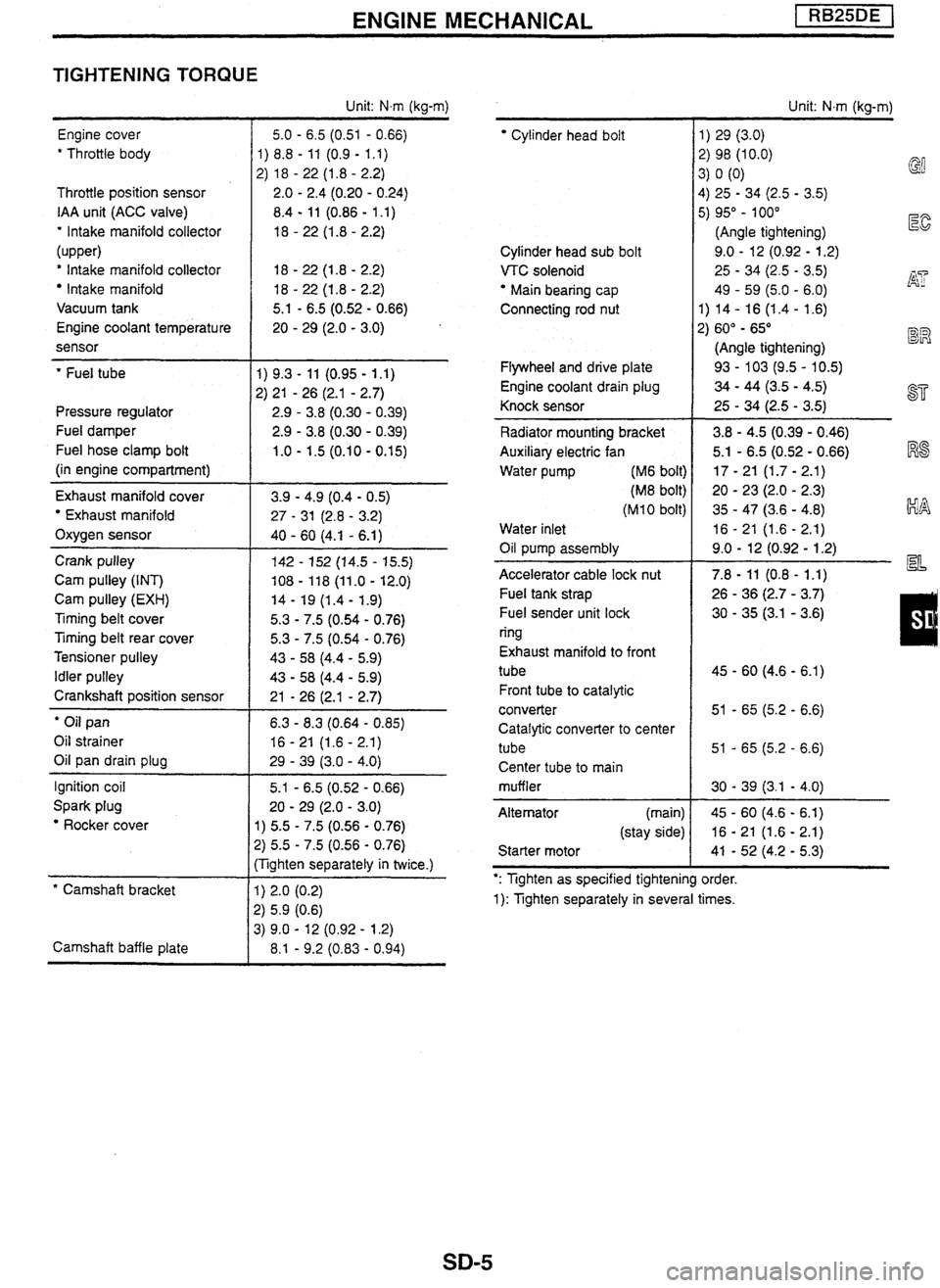
ENGINE MECHANICAL
TIGHTENING TORQUE
Engine cover
' Throttle body
Throttle position sensor
IAA unit (ACC valve)
' Intake manifold collector
(upper)
' Intake manifold collector
Intake manifold
Vacuum tank
Engine coolant temperature
sensor
' Fuel tube
Pressure regulator
Fuel damper
Fuel hose clamp bolt
(in engine compartment)
Exhaust manifold cover
Exhaust manifold
Oxygen sensor
Crank pulley
Cam pulley (INT)
Cam pulley
(EXH)
Timing belt cover
Ttming belt rear cover
Tensioner pulley
Idler pulley
Crankshaft position sensor
' Oil pan
Oil strainer
Oil pan drain plug
Ignition coil
Spark plug
Rocker cover
* Camshaft bracket
Camshaft baffle plate Unit:
Nm (kg-m)
5.0
- 6.5 (0.51 - 0.66)
1) 8.8
- 11 (0.9 - 1.1)
2) 18
- 22 (1.8 - 2.2)
2.0
- 2.4 (0.20 - 0.24)
8.4
- 11 (0.86 - 1 .I)
18
- 22 (1.8 - 2.2)
5.1
- 6.5 (0.52 - 0.66)
20
- 29 (2.0 - 3.0)
1) 5.5 - 7.5 (0.56 - 0.76)
2) 5.5 - 7.5 (0.56 - 0.76)
:Tighten separately in twice.)
Cylinder head bolt
Cylinder head sub bolt
VTC solenoid
Main bearing cap
Connecting rod nut
Flywheel and drive plate
Engine coolant drain plug
Knock sensor
Radiator mounting bracket
Auxiliary electric fan
Water pump
(M6 bolt)
(M8 bolt)
(M 1 0 bolt)
Water inlet
Oil pump assembly
-
Accelerator cable lock nut
Fuel tank strap
Fuel sender unit lock
ring
Exhaust manifold to front
tube
Front tube to catalytic
converter
Catalytic converter to center
tube Center tube to main
muffler
Alternator (main)
(stay side)
Starter motor Unit:
N.m (kg-m)
1) 29 (3.0)
2) 98 (10.0) 3) 0 (0)
@
4)
25 - 34 (2.5 - 3.5)
5) 95" - 100"
(Angle tightening)
E
9.0 - 12 (0.92 - 1.2)
25
- 34 (2.5 - 3.5) j$? 49 - 59 (5.0 - 6.0)
1) 14- 16
(1.4- 1.6)
2) 60"
- 65" BR
(Angle tightening)
93
- 103 (9.5 - 10.5)
34 - 44 (3.5 - 4.5)
25
- 34 (2.5 - 3.5) a=
': Tighten as specified tightening order.
1): Tighten separately in several times.
Page 207 of 230

ENGINE MECHANICAL pEZBq
TIGHTENING TORQUE
Engine cover
' Throttle body
Throttle position sensor
IAA unit
(ACC valve)
' Intake manifold collector
* Intake manifold
Engine coolant temperature
sensor
' Fuel tube
Pressure regulator
Fuel damper
Fuel hose clamp bolt
(in engine compartment)
Turbocharger Oil tube
Water tube (block side)
(turbocharger side)
Oxygen sensor
Exhaust manifold cover
' Exhaust manifold
Crank pulley
Cam pulley (INT)
Cam pulley
(EXH)
Timing belt cover
Timing belt rear cover
Tensioner pulley
Idler pulley
Crankshaft position sensor
' Oil pan
Oil strainer
Oil pan drain plug
Ignition coil
Spark plug
' Rocker cover
' Camshaft bracket
Camshaft baffle plate Unit:
N.m (kg-m)
5.0
- 6.5 (0.51 - 0.66)
1)
8.8
- 11 (0.9 - 1.1)
2)
18
- 22 (1 -8 - 2.2)
2.0
- 2.4 (0.20 - 0.24)
8.4
- 11 (0.86 - 1.1)
18
- 22 (1.8 - 2.2)
18
- 22 (1 -8 - 2.2)
20
- 29 (2.0 - 3.0)
5.1
- 6.5 (0.52 - 0.66)
20
- 29 (2.0 - 3.0)
1) 5.5
- 7.5 (0.56 - 0.76)
2) 5.5 - 7.5 (0.56 - 0.76)
(Tighten separately in twice.)
' Cylinder head boit
Cylinder head sub bolt
VTC solenoid
" Main bearing cap
Connecting rod
nut
Oil jet
Flywheel and drive plate
Engine coolant drain plug
Knock sensor
Radiator mounting bracket
Auxiliary electric fan
Water pump (M6 bolt)
(M8 bolt)
(MI
0 bolt)
Water inlet
Oil pump assembly
Accelerator cable lock nut
Fuel tank strap
Fuel sender unit lock
ring
Exhaust manifold to front
tube
Front tube to catalytic
converter
Catalytic converter to center
tube
Center tube to main
muffler
Alternator (main)
(stay side)
Starter motor Unit:
N.m (kg-m)
1) 29 (3.0)
2) 98 (10.0)
3) 0 (0)
4) 25 - 34 (2.5 - 3.5)
5) 95"
- 100"
(Angle tightening)
I%
9.0 - 12 (0.92 - 1.2)
25
- 34 (2.5 - 3.5)
49
- 59 (5.0 - 6.0) AT
1) 14 - 16 (1.4 - 1.6)
2) 60" - 65"
(Angle tightening) BR
30 - 40 (3.1 - 4.1)
93
- 103 (9.5 - 10.5)
34 - 44 (3.5 - 4.5) ST
25 - 34 (2.5 - 3.5)
3.8
- 4.5 (0.39 - 0.46) I%$
5.1 - 6.5 (0.52 - 0.66)
17
- 21 (1.7 - 2.1)
20
- 23 (2.0 - 2.3) kIA
35 - 47 (3.6 - 4.8)
16
- 21 (1.6 - 2.1)
9.0
- 12 (0.92 - 1.2) a=
': Tighten as specified tightening order.
1): Tighten separately in several times.