check engine NISSAN GT-R 1998 Service Manual
[x] Cancel search | Manufacturer: NISSAN, Model Year: 1998, Model line: GT-R, Model: NISSAN GT-R 1998Pages: 230, PDF Size: 12.66 MB
Page 5 of 230
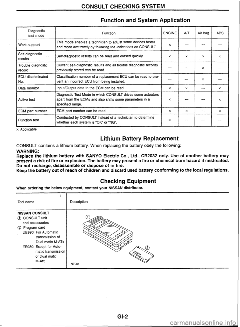
CONSULT CHECKING SYSTEM
Function and System Application
Diagnostic test mode
Work support
Self-diagnostic results
Trouble diagnostic record Function
This mode enables a technician to adjust some devices faster
and more accurately by following the indications on CONSULT.
ECU discriminated
No.
Data monitor
I I whether each system is "OK" or 'NG". lxH-1-
Conducted by CONSULT instead of a technician to determine
Function test Self-diagnostic
results can be read and erased quickly.
Current self-diagnostic results and all trouble diagnostic records
previously stored can be read.
Active test
ECM part number
L x: Applicable ENGINE
x
Classification
number of a replacement ECU can be read to pre-
vent an incorrect ECU from being installed.
InputIOutput data in the ECM can be read.
Lithium Battery Replacement
x
Diagnostic Test Mode in which CONSULT drives some actuators
apart from the
ECMs and also shifts some parameters
in a
specified range.
ECM part number can be read.
CONSULT contains a lithium battery. When replacing the battery obey the following:
WARNING:
Replace the lithium battery with SANYO Electric Co., Ltd.,
CR2032 only. Use of another battery may
present
a risk of fire or explosion. The battery may present a fire or chemical burn hazard if mistreated.
Do not recharge, disassemble or dispose of in fire.
Keep the battery out of reach of children and discard used battery conforming to the local regulations.
AfT
-
-
x
Checking Equipment
x
-
x
x
When ordering the below equipment, contact your NlSSAN distributor. Air
bag
-
-
-
x
!
Tool name ABS
-
x
X
-
x
NISSAN CONSULT
@ CONSULT unit
and accessories
@ Program card
UE990: For Automatic
transmission of
Dual
rnatic M-ATx
EE980: Except for Auto-
matic transmission
of Dual
matic
M-Atx
x
-
--
X
-
Description
-
x
-
-
x
x
Page 18 of 230

ENGINE AND EMISSION CONTROL OVERALL SYSTEM
Circuit Diagram
RB20DE (UB).MTT, RB25DE, RB25DET.MTT MODELS
Fan motor
Auxtliary
electric
Ian
relay
-
Alr cmdll~oner compressor
Arr
conduoner
relay
14
Y Mallunct~on indcator lamp A 17
26 $7 = Power steenng 011
pressure sw~icr.
I
23
43 Engine Want
temwrature sensor B.
Tachometer drive signal Check connmr
To rear defogger relay
/ [RB2MWD TO starter motor *'""L'*" - > TO PNP switch
I TO Starter relay
[Except lor ' - RB25DE.4WDI
Page 20 of 230
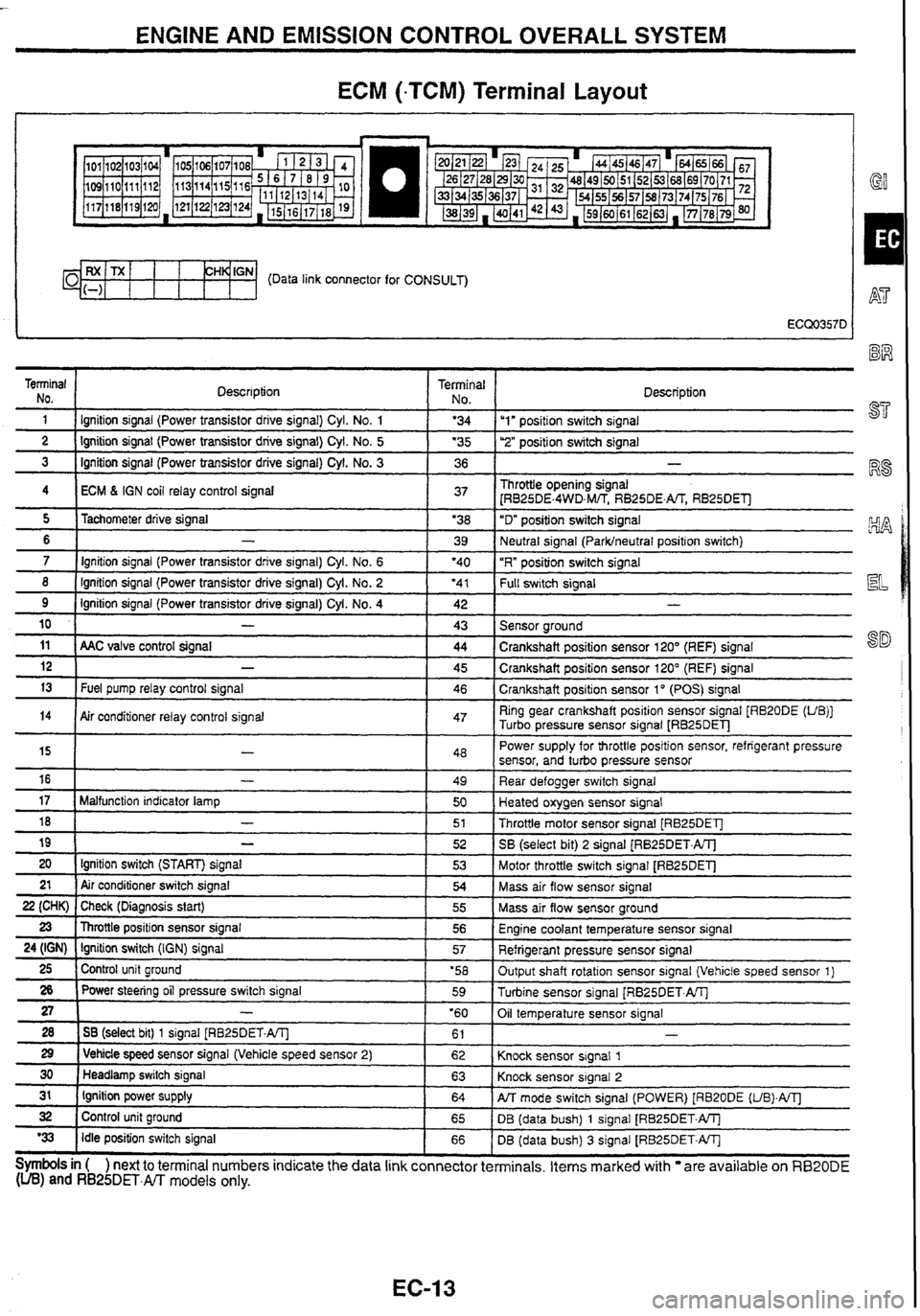
ENGINE AND EMISSION CONTROL OVERALL SYSTEM
ECM (-TCM) Terminal Layout
I GY
CH~'GN- (Data link connector for CONSULT)
Terminal NO.
1 Description Terminal 1 No I Description - - 1 I lgnition
signal (Power transistor drrve signal) Cyl. No. 1 1 '34 Iu1" positron switch signal -- ---- 2 1 Ignition signal (Power transistor drive signal) Cyl. No. 5 1 '35 1 ''2" posifion switch signal - - 3 1 Ignition signal (Power transistor drive signal) Cyl. No. 3 1 36 1 -
4 I ECM 6 IGN coil relay control signal 1 37 1 Throttle opening signal
[RB25DE.4WD,M/TS RB25DE.m RB25DEll
- - - -- - - - - 8 ( Ignition signal (Power transistor drive signal) Cyl. No. 2 ( '41 1 f-k swltch signal
5
6
7
11 ( AAC valve control signal ( 44 1 Crankshaft position sensor 120' (REF) signal
Tachometer
drive signal
-
Ignition signal (Power transistor drive signal) Cyl. No. 6
9
10
'38
39
'40
Ignition signal (Power transistor drive signal)
Cyl.
No. 4
-
12
13
"D" position switch signal
Neutral signal
(Parklneutral position switch)
"R" position switch signal
14
Symbols in ( ) next to terminal numbers indicate the data link connector terminals. Items marked with are available on RB20DE (UB) and RB25DET.m models only.
42
43
-
Fuel pump relay control signal
15
16
17
18
19
20 21
22 (CHK)
23
24 (IGN)
25
26
27
28
29
30
31
32
'33
- -
Sensor around
Air conditioner relay control signal 45
46
-
-
Malfunction indicator lamp
-
-
Ignition switch (START) signal
Air conditioner switch signal
Check (Diagnosis start)
Throttle position sensor signal
Ignition switch
(IGN) signal
Control unit ground
Power steering oil pressure switch signal
-
1 SB (select bit) 1 signal [RB25DET.A/Tl
1 Vehicle speed sensor signal (Vehicle speed sensor 2)
Headlamp switch signal
Ignition power supply
Control unit ground
Idle position switch signal Crankshaft
position sensor 120" (REF) signal
Crankshaft position sensor 1
" (POS) signal
47 Ring gear crankshaft position sensor signal [RB20DE (UB)]
Turbo pressure sensor signal
LRB25DEl-J
48
49
50
51
52
53
54
55
56
57
'58 59
'60 61
62
63
64
65
66 Power
supply for throttle position sensor, refrigerant pressure
sensor, and turbo pressure sensor
Rear defogger switch signal
Heated oxygen sensor signal
Throttle motor sensor signal [RB25DET]
SB
(select bit)
2 signal (RB25DET.ATJ
Motor throttle switch signal
[RB25DET]
Mass air flow sensor signal
Mass air flow sensor ground
Engine coolant temperature sensor signal
Refrigerant pressure sensor signal
Output shaft rotation sensor signal (Vehicle speed sensor 1)
Turbine sensor signal
[RB25DET.AlTj
Oil temperature sensor signal
Knock sensor signal
1
Knock sensor signal 2
PJT mode switch signal (POWER) [RB20DE (UB).A/Tl
DB (data bush) 1 signal [RB25DET.W
DB (data bush)
3 signal [RB25DET.W
Page 24 of 230
TROUBLE DIAGNOSES
Self-diagnosis (Cont'd)
I Malfunction indicator lamp
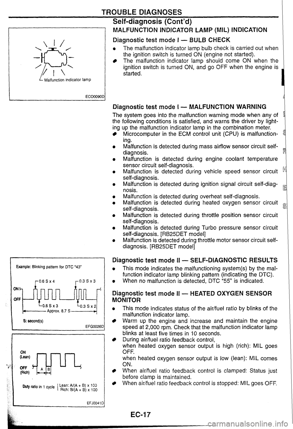
MALFUNCTiON INDICATOR LAMP (MIL) INDICATION
Diagnostic test mode I - BULB CHECK
0 The malfunction indicator lamp bulb check is carried out when
the ignition switch is turned
ON (engine not started).
The malfunction indicator lamp should come ON when the
ignition switch is turned
ON, and go OFF when the engine is
started.
Example: Blinking pattern for DTC "43"
ONh
OFF
Approx. 8.7 S
OFF (Rich)
Duty ratio in 1 cycle 1 Lean: Al(A + B) x 100 Rich: B/(A + B) x 100
EFJ0041 C
Diagnostic test mode I - MALFUNCTION WARNING
The system goes into the malfunction warning mode when any of
the following conditions is satisfied, and warns the driver by light-
ing up the malfunction indicator lamp in the combination meter.
Microcomputer in the ECM control unit (CPU) is malfunction-
1
ing.
Malfunction is detected during mass airflow sensor circuit self-
diagnosis.
Malfunction is detected during engine coolant temperature
sensor circuit self-diagnosis.
Malfunction is detected during vehicle speed sensor circuit
self-diagnosis.
Malfunction is detected during ignition signal circuit
self-diag-
nosis.
Malfunction is detected during overheat self-diagnosis.
Malfunction is detected during heated oxygen sensor circuit
self-diagnosis.
~alfunsion is detected during throttle position sensor circuit
self-diagnosis.
Malfunction is detected during Turbo pressure sensor circuit
self-diagnosis.
[RB25DET model]
Malfunction is detected during throttle motor sensor circuit self-
diagnosis.
[RB25DET model]
Diagnostic test mode I1 - SELF-DIAGNOSTIC RESULTS
0 This mode indicates the malfunctioning system(s) by the mal-
function indicator lamp blinking pattern (indicating the DTC).
0 When no malfunction is detected, DTC "55" is indicated.
Diagnostic test mode II - HEATED OXYGEN SENSOR
MONITOR
0 This mode indicates status of the aidfuel ratio by blinks of the
malfunction indicator lamp.
Warm up the engine and increase and maintain the engine
speed at 2,000 rpm. Check that the malfunction indicator lamp
blinks at least five times in
10 seconds.
During airlfuel ratio feedback control,
when heated oxygen sensor output is high (rich): MIL goes
OFF.
when heated oxygen sensor output is low (lean):
MIL comes
ON.
When aidfuel ratio feedback control is clamped: Status just
before clamp
is maintained.
When airifuel ratio feedback control is stopped: MIL goes OFF.
Page 25 of 230
TROUBLE DIAGNOSES
Self-diagnosis
(Cont'd)
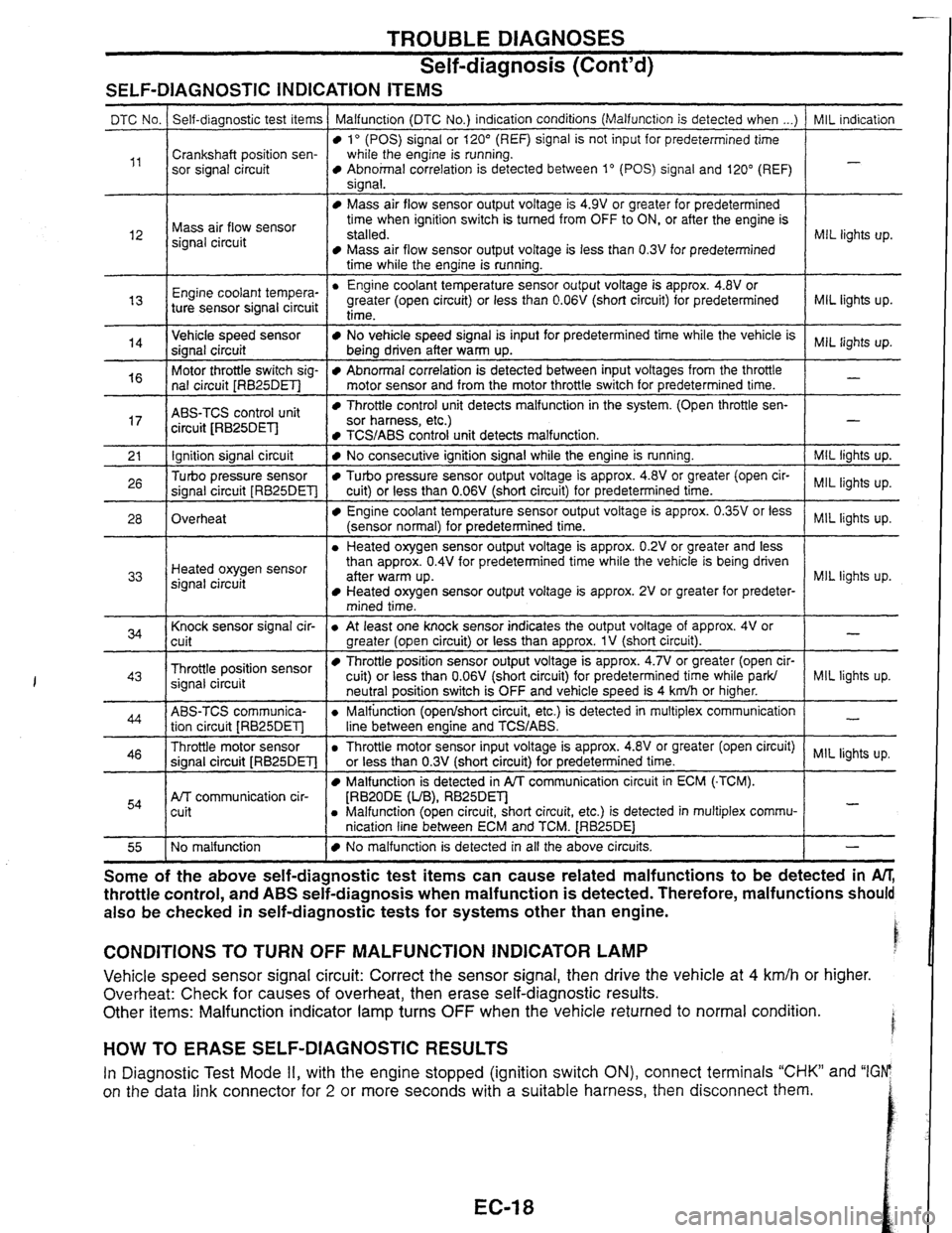
SELF-DIAGNOSTIC INDICATION ITEMS
I time while the engine is running. I
MIL indication
-
DTC No.
,,
MIL lights up. l2
Self-diagnostic test items
Crankshaft position sen-
sor signal circuit Malfunction (DTC No.)
indication conditions (Malfunction is detected when ...)
lo (POS) signal or 120" (REF) signal is not input for predetermined time
while the engine is running.
Abnohal correlation is detected between 1" (POS) signal and 120" (REF)
sianal.
Mass air flow sensor
signal circuit
MIL lights up.
Engine coo'ant tempera-
"
Mass air flow sensor output voltage is 4.9V or greater for predetermined
time when ignition switch is turned from OFF to ON, or after the engine is
stalled.
Mass air flow sensor output voltage is less than 0.3V for predetermined
Engine coolant temperature sensor output voltage is approx.
4.8V or
greater (open circuit) or less than
0.06V (short circuit) for predetermined
MIL lights up.
-
14
ABS-TCS control unit
circuit JRB25DEl-l
ture sensor signal circuit Throttle control unit detects malfunction
in the system. (Open throttle sen- sor harness, etc.)
Ignition signal circuit
Turbo pressure sensor
signal circuit
[RB25DET]
Overheat
I 1 mined time. I
time-
Vehicle speed sensor
signal circuit
Motor throttle switch sig-
nal circuit
[RB25DET]
TCS/ABS control unit detects malfunction. 1 -
I Knock sensor signal cir-
cuit
- --
No vehicle speed signal is input for predetermined time while the vehicle is
being driven after warm up.
Abnormal correlation is detected between input voltages from the throttle
motor sensor and from the motor throttle switch for predetermined time.
I
MIL lights up. Heated oxygen sensor
signal circuit
Throttle position sensor
signal circuit
No consecutive ignition signal while the engine is running.
Turbo pressure sensor output voltage is approx. 4.8V or greater (open cir-
cuit) or less than
0.06V (short circuit) for predetermined time.
Engine coolant temperature sensor output voltage is approx. 0.35V or less
(sensor normal) for predetermined time.
a Heated oxygen sensor output voltage is approx. 0.2V or greater and less
than approx.
0.4V for predetermined time while the vehicle is being driven
aner warm up. Heated oxygen sensor output voltage is approx. 2V or greater for predeter-
ABS-TCS communica- tion circuit
[RB25DET]
Throttle motor sensor
signal circuit
[RB25DET]
Afr communication cir-
cuit
MIL lights up.
lights
up.
MIL lights up.
NQ malfunction
I a At least one knock sensor indicates the output voltage of approx. 4V or
greater (open circuit) or less than approx.
1V (short circuit).
Throttle position sensor output voltage is approx. 4.7V or greater (open cir-
cuit) or less than
0.06V
(short circuit) for predetermined time while ark/
a Throttle motor sensor input voltage is approx. 418~or greater (open circuit) MIL lights up.
or less than
0.3V
(short circuit) for predetermined time. I
-
MIL liqhts up. neutral position switch is OFF and vehicle speed is 4 kdh or higher.
a Malfunction (openlshort circuit, etc.) is detected in multiplex communication
line between enaine and
TCWABS.
Malfunction is detected in PA communication circuit in ECM (-TCM).
[RBZODE (UB), RB25Dm a Malfunction (open circuit, short circuit, etc.) is detected in multiplex commu-
nication line between ECM and TCM.
[RB25DE1
-
-
No malfunction is detected in all the above circuits. I - - --
Some of the above ~elfaia~nostic test items can cause related malfunctions to be detected in M,
throttle control, and ABS seif-diagnosis when malfunction is detected. Therefore, malfunctions should
also be checked in self-diagnostic tests for systems other than engine.
CONDITIONS TO TURN OFF MALFUNCTION INDICATOR LAMP
Vehicle speed sensor signal circuit: Correct the sensor signal, then drive the vehicle at 4 km/h or higher.
Overheat: Check
for causes of overheat, then erase self-diagnostic results.
Other items: Malfunction indicator lamp turns
OFF when the vehicle returned to normal condition.
HOW TO ERASE SELF-DIAGNOSTIC RESULTS
In Diagnostic Test Mode II, with the engine stopped (ignition switch ON), connect terminals "CHK" and "IGFP
on the data link connector for
2 or more seconds with a suitable harness, then disconnect them.
Page 27 of 230
TROUBLE DIAGNOSES
CONSULT (Cont'd)
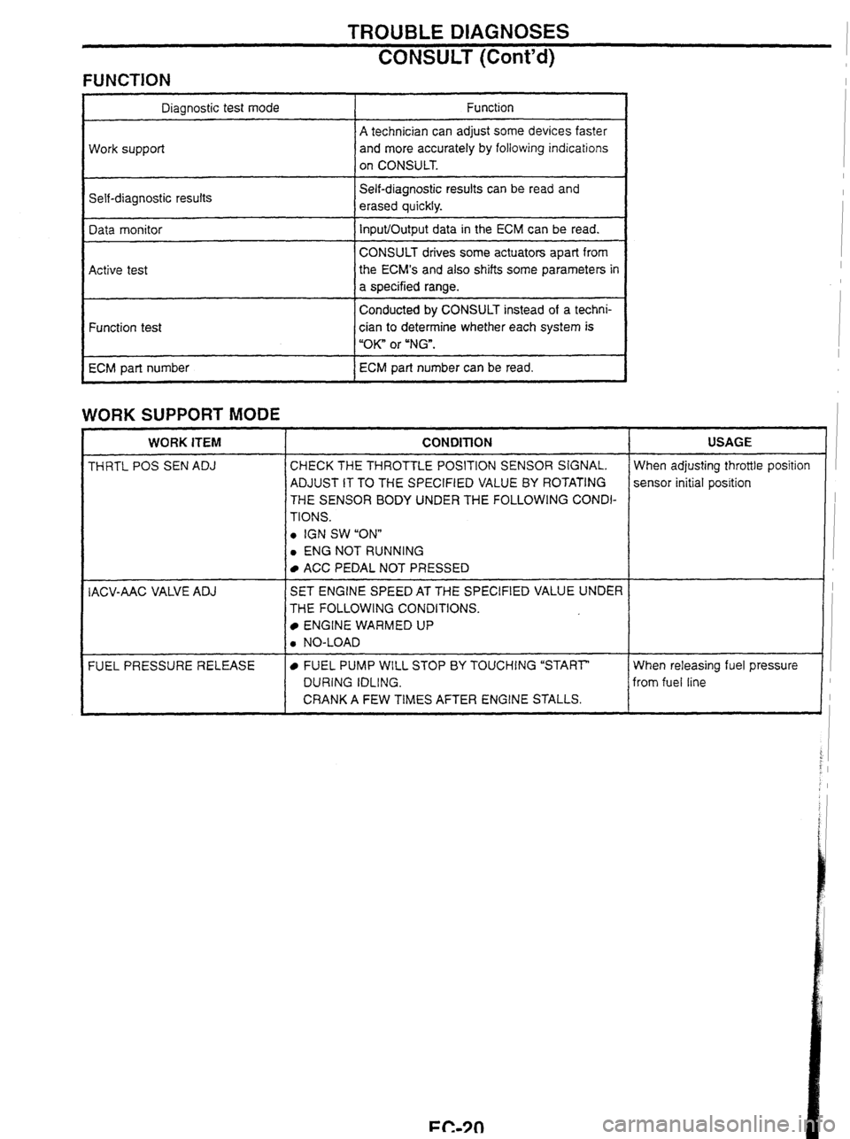
FUNCTION
Self-diagnostic results Diagnostic test mode
Work support
Self-diagnostic resuits can
be read and
erased quickly. Function
A technician can adjust some devices faster
and more accurately by following indications
on CONSULT.
Data monitor
Active test
WORK SUPPORT MODE
Input/Output data in the ECM can be read.
CONSULT drives some actuators apart from
the
ECM's and
also shifts some parameters in
a specified range.
Conducted
by CONSULT instead of a techni-
Function test
ECM part number
WORK ITEM I CONDITION I USAGE
cian to determine whether each system is
"OK" or
"NG".
ECM part number can be read.
THRTL
POS SEN ADJ CHECK THE THROTTLE POSITION SENSOR SIGNAL.
ADJUST IT TO THE SPECIFIED VALUE
BY ROTATING
THE SENSOR BODY UNDER THE FOLLOWING CONDI-
TIONS.
0 IGN SW "ONn
0 ENG NOT RUNNING When adjusting
throttle position
sensor initial position
I ACC PEDAL NOT PRESSED 1 I
IACV-AAC VALVE ADJ I SET ENGINE SPEED AT THE SPECIFIED VALUE UNDER I 1 THE FOLLOWING CONDITIONS.
ENGINE WARMED UP
When releasing fuel pressure I
from fuel line
FUEL
PRESSURE RELEASE
0 NO-LOAD
FUEL PUMP WILL STOP BY TOUCHING "START"
DURING IDLING.
CRANK A FEW TIMES AFTER ENGINE STALLS.
i J
Page 28 of 230
TROUBLE DIAGNOSES m
CONSULT (Cont'd)
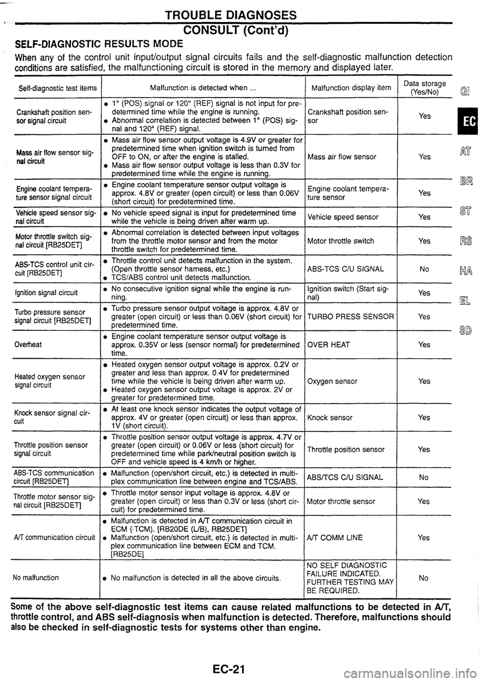
SELF-DIAGNOSTIC RESULTS MODE
When any of the control unit input/output signal circuits fails and the self-diagnostic malfunction detection
conditions
are satisfied, the malfunctioning circuit is stored in the memory and displayed later.
Self-diagnostic test items I Malfunction is detected when ... Data storage
Malfunction display item I (Yes/No,
Crankshaft position sen-
sor signal circuit
I predetermined time while the engine is running. 1 1 mm
Mass air 'low sensor sig- nal circuit
1" (POS) signal or 120" (REF) signal is not input for pre-
determined time while the engine is running.
Abnormal correlation is detected between 1" (POS) sig-
nal and 120" (REF) signal.
Mass air flow sensor output voltage is 4.9V or greater for
Vehicle speed sensor sig-
No vehicle speed signal is input for predetermined time Vehicle speed sensor I I Yes ST nal
circuit I while the vehicle is beina driven after warm UD.
predetermined time when ignition switch is turned from
OFF to ON, or after the engine is stalled.
Mass air flow sensor output voltage is less than 0.3V for
Engine coolant tempera-
ture sensor signal circuit
Crankshaft position sen-
sor
Mass air flow sensor
AT
Yes RS
-.
yes I
Engine coolant temperature sensor output voltage is
approx. 4.8V or greater (open circuit) or less than 0.06V
(short circuit) for predetermined time.
switch sig- nal circuit JRB25DETI
Engine coolant tempera- ture sensor
Abnormal correlation is detected between input voltages
from the throttle motor sensor and from the motor
throttle switch for predetermined time.
ABS-TCS control unit cir- cuit [RB25DETJ
19 L~J
Yes
--
Motor throttle switch
lgnition signal circuit
Turbo pressure sensor
signal circuit [RB25DETl
Overheat
Yes
Throttle control unit detects malfunction in the system.
(Open throttle sensor harness, etc.)
TCS/ABS control unit detects malfunction.
Heated oxygen sensor signal circuit ABS-TCS
C/U SIGNAL
No consecutive ignition
signal while the engine is run-
ning.
Turbo pressure sensor output voltage is approx. 4.8V or
greater (open circuit) or less than
0.06V (short circuit) for
predetermined time.
Engine coolant temperature sensor output voltage is
approx.
0.35V or less (sensor normal) for predetermined
time.
Yes
Heated oxygen sensor output voltage is approx. 0.2V or
greater and less than approx.
0.4V for predetermined
time while the vehicle is being driven after warm up.
Heated oxygen sensor output voltage is approx. 2V or
greater for medetermined time.
Knock cuit lgnition
switch (Start sig-
nal)
TURBO PRESS SENSOR
OVER HEAT
Oxygen sensor
Yes Yes
EL
Yes
8D
Yes
At
least one knock sensor indicates the output voltage of
approx. 4V or greater (open circuit) or less than approx.
1 V (short circuit).
Throttle position sensor
signal circuit
ABS-TCS communication
Malfunction (openlshort circuit, etc.) is detected in multi- ABSrrCS C,u circuit [RB25DETl 1 plex communication line between enaine and TCS/ABS. I
Knock sensor
Throttle position sensor output voltage is approx. 4.7V or
greater (open circuit) or
0.06V or less (short circuit) for
predetermined time while
parkheutral position switch is
OFF and vehicle
s~eed is 4
km/h or hiaher. Thronle
position sensor
Throttle motor sensor sig- nal circuit
[RB25DET] Yes
AiT communication
circuit
Yes
Throttle motor sensor input voltage is approx. 4.8V or
greater (open circuit) or less than
0.3V or less (short cir-
cuitl for
redetermined time.
No malfunction Motor
throttle sensor
Malfunction is detected in A/T communication circuit in
ECM
(.TCM).
(RB2ODE
(UB), RB25DET]
a Malfunction (opedshort circuit, etc.) is detected in multi-
plex communication line between ECM and TCM.
[RB25DE1
No malfunction is detected in all the above circuits.
A/T COMM LINE
NO SELF DIAGNOSTIC
FAILURE INDICATED.
FURTHER TESTING MAY
BE REQUIRED.
Some of the above self-diagnostic test items can cause related malfunctions to be detected in An;
throttle control, and ABS self-diagnosis when malfunction is detected. Therefore, malfunctions should
also
be checked in self-diagnostic tests for systems other than engine.
Page 31 of 230
TROUBLE DIAGNOSES
CONSULT (Cont'd)
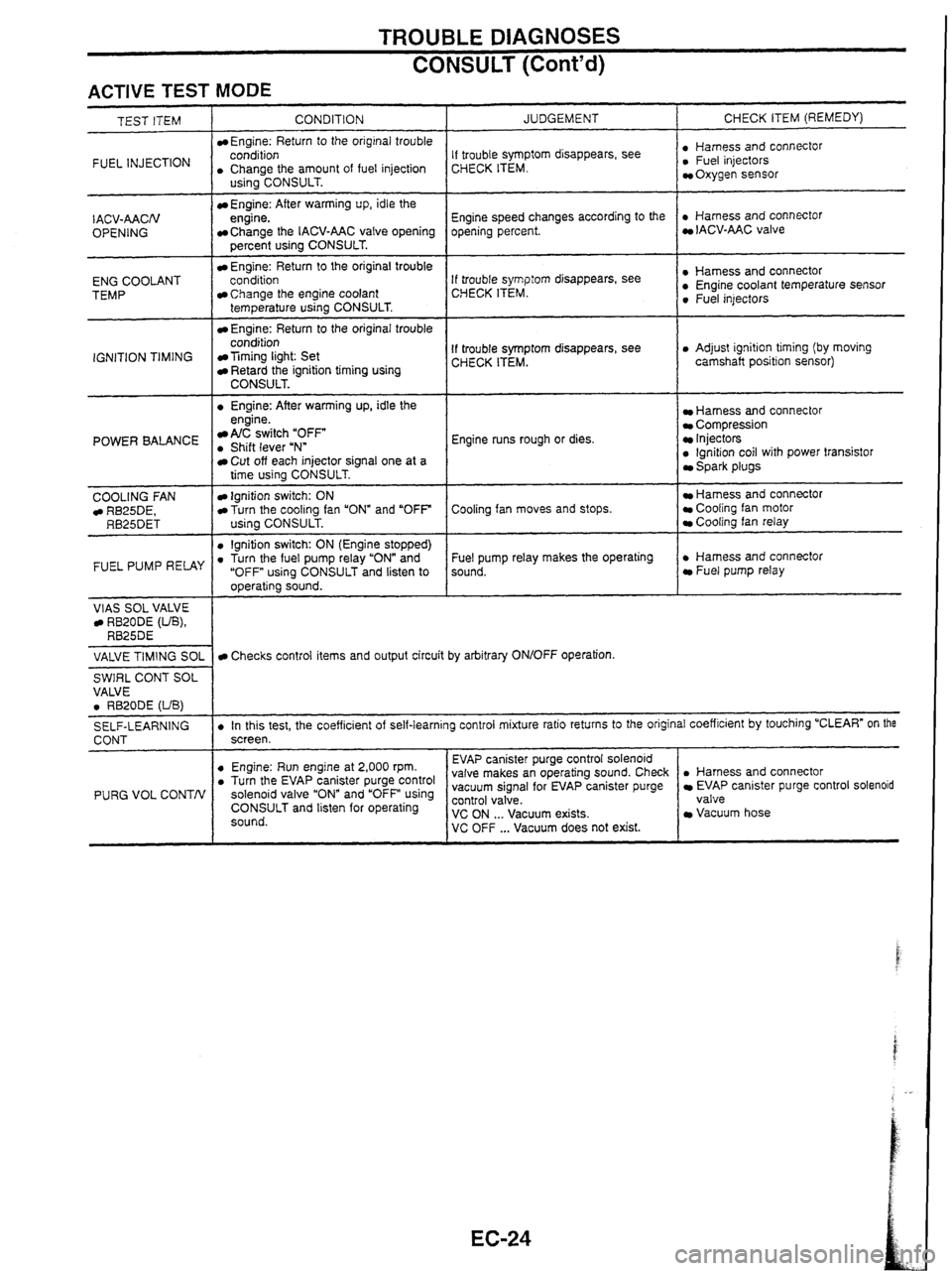
ACTIVE TEST MODE
INJECTION I . CCohArthe amount of fuel injection
TEST ITEM
CONDITION
Engine: Return
to the original trouble
- I . Engine: After warming up, idle the
IACV-AACN
OPENING
ENG COOLANT
TEMP
IGNITION TIMING
US~~~CONSULT.
Engine: After warming up, idle the
engine.
Change the IACV-AAC valve opening
percent using CONSULT.
Engine: Return to the original trouble
conditioo
Change the engine coolant
temperature using CONSULT.
Engine: Return to the original trouble
condition
Timing light: Set Retard the ignition timing using CONSULT.
POWER BALANCE engine. A/C switch "OFF . Shift lever uNn
COOLING
FAN RB25DE, RB25DET
FUEL PUMP RELAY
VlAS SOL VALVE RB20DE (UB), RB25DE
JUDGEMENT
Cut off each injector signal one at a
time using CONSULT.
Ignition switch: ON Turn the cooling fan "ON" and "OFF
using CONSULT.
0 lgnition switch: ON (Engine stopped) . Turn the fuel pump relay "ON" and
"OFF using CONSULT and listen to
operating sound. CHECK
ITEM (REMEDY)
If trouble symptom disappears, see
CHECK ITEM. : ~,"~~,,,~scOnnectOr Oxygen sensor
Engine speed changes according to the
opening percent.
. Harness and connector IACV-AAC valve
If trouble
symp:orn disappears, see
CHECK ITEM. : Sensor 0 Fuel injectors
If trouble symptom disappears, see
CHECK ITEM. 0 Adjust ignition timing (by moving
camshaft position sensor)
Engine runs rough or dies.
Harness and connector Compression Injectors 0 lgnition coil with power transistor Spark plugs
Cooling fan moves and stops.
Hamess and connector Cooling fan motor Cooling fan relay
Fuel pump relay makes the operating
sound.
. Harness and connector Fuel pump relay
VALVE
TIMING
SOL
SWIRL CONT SOL
VALVE
0 RB20DE (UB)
SELF-LEARNING
CONT
PURG VOL CONTN
Checks control items and output circuit by arbitrary ON/OFF operation.
. In this test, the coefficient of self-learning control mixture ratio returns to the original coefficient by touching "CLEAR" on the
screen.
. Harness and connector EVAP canister purge control solenoid
valve
Vacuum hose
0 Engine: Run engine at 2,000 rpm. . Turn the EV~P canister purge control solenoid valve and using CONSULT and listen for operating
sound. EVAP
canister purge control solenoid
valve makes an operating sound. Check
vacuum signal for EVAP canister purge ~~~~~~a'cuum exists. VC OFF ... Vacuum does not exist.
Page 33 of 230

TROUBLE DIAGNOSES t i
CONSULT (Cont'd) i
FUNCTION TEST MODE
CHECK ITEM (REMEDY)
FUNCTION
TEST
ITEM JUDGEMENT
CONDITION
lgnition switch: ON
(Engine stopped)
Displays the results of on board
diagnostic system.
SELF-DIAG
RESULTS Objective
system
--
ignition switch: ON
(Engine stopped)
Throttle position sensor circuit is
tested when throttle is opened and
closed fully. ("IDLE POSITION" is
the test item name for the vehicles
in which idle is selected by throttle
position sensor.) Harness and connector
Throttle position sensor (Closed
throttle position)
Throttle position sensor (Closed
throttle position) adjustment
Throttle linkage
Venfy operation in DATA
MONITOR mode.
Throttle
valve:
opened OFF
ON
CLOSED THROTTLE
POSl Throttle valve:
closed
lgnition switch: ON
(Engine stopped)
Throttle position sensor circuit is
tested when throttle is opened and
closed fully.
Harness and connector
Throttle position sensor
Throttle position sensor
adjustment
Throttle linkage
Verify operation in DATA
MONITOR mode.
Range
(Throttle
valve fully opened
- Throttle valve
fully closed) More
than 3.0V THROTTLE POSl
SEN CKT
lgnition switch: ON
(Engine stopped)
Neutral position switch circuit is
tested when shift lever is
manipulated.
lgnition switch: ON
(Engine stopped)
Fuel pump circuit is tested by
checking the pulsation in fuel
pressure when fuel tube is
pinched. Out of
N/P
positions OFF
Harness
and connector
Neutral position switch
Linkage adjustment
PARWNEUT POSl SW CKT
In
N/P positions
Harness and connector
Fuel pump
Fuel pump relay
Fuel filter clogging
Fuel level
There
is pressure pulsation on
the fuel feed hose.
FUEL PUMP
CIRCUIT
--
The valve timing control system is
diagnosed by checking for
operating sound of the solenoid
valve.
lgnition switch: ON
(Engine stopped)
Cooling fan circuit is tested when
cooling fan is rotated.
VALVE
TIMING
SN
CKT
Harness and connector
Cooling fan motor
Cooling fan relay
COOLING
FAN
CIRCUIT RB25DE, RB25DET
The cooling fan rotates and
stops every
3 seconds.
lgnition switch: ON -+ START
Start signal circuit is tested when
engine is started by operating the
starter. Battery voltage and water
temperature before cranking, and
average battery voltage, mass air
flow sensor output voltage and
cranking speed during cranking
are displayed.
Harness and connector
lgnition switch
START
SIGNAL
CIRCUIT Start
signal: OFF 3 ON
Page 34 of 230
TROUBLE DIAGNOSES
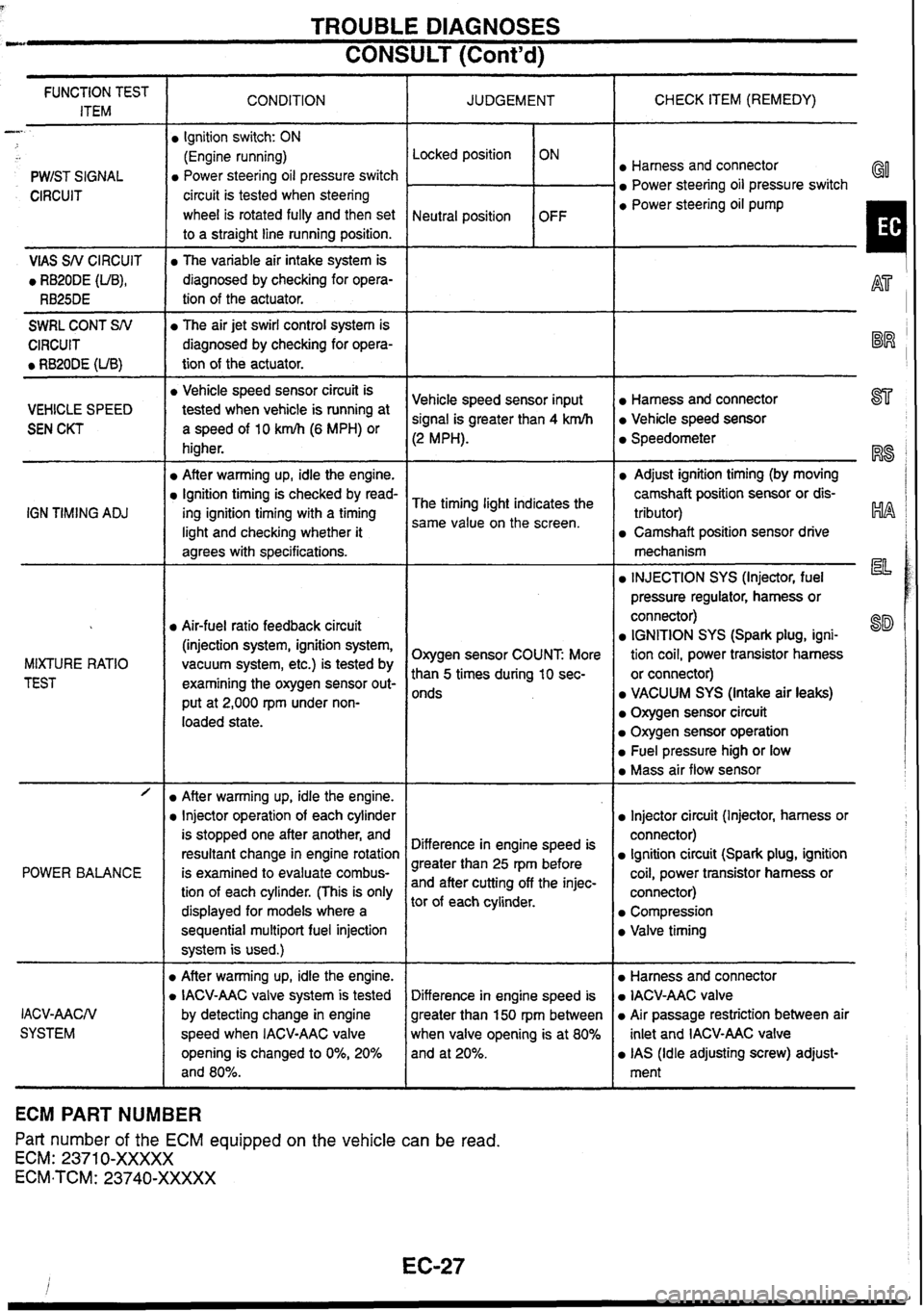
CONSULT (Cont'd) --
CHECK ITEM (REMEDY)
FUNCTION TEST
ITEM CONDITION
JUDGEMENT
-
PWIST SIGNAL Locked position
Neutral position
Ignition
switch: ON
(Engine running)
Power steering oil pressure switch
circuit is tested when steering
wheel is rotated fully and then set
to a straight line running position. ON
OFF Harness and connector
Power steering oil pressure switch GO
CIRCUIT a Power steering oil pump
I VlAS SN CIRCUIT
0 RB20DE (UB),
RB25DE
The variable air intake system is
diagnosed by checking for opera-
tion of the actuator.
-
SWRL CONT SN
CIRCUIT
0 RB20DE (UB)
The air jet swirl control system is
diagnosed by checking for opera-
tion of the actuator.
-- -- -
a Vehicle speed sensor circuit is
tested when vehicle
is running at
a speed of 10 km/h (6 MPH) or
higher.
After warming up, idle the engine.
Ignition timing is checked by read-
ing ignition timing with a timing
light and checking whether it
agrees with specifications.
Harness and connector 877
Vehicle speed sensor
Vehicle
speed sensor input
signal is greater than 4 krnlh
(2 MPH).
VEHICLE SPEED
SEN CKT Speedometer
RS
Adjust ignition timing (by moving
camshaft position sensor or dis-
tributor)
HA
Camshaft position sensor drive
The
timing light indicates the
same value on the screen.
IGN
TIMING
ADJ
mechanism
la INJECTION SYS (Injector, fuel
pressure regulator, harness or
connector)
IGNITION SYS (Spark plug, igni-
tion coil, power transistor harness
or connector)
VACUUM SYS (Intake air leaks)
Oxygen sensor circuit
Oxygen sensor operation
Fuel pressure high or low
Mass air flow sensor
Air-fuel ratio feedback circuit
(injection system, ignition system,
vacuum system, etc.) is tested by
examining the oxygen sensor out-
put at 2,000
rpm under non-
loaded state. Oxygen sensor COUNT
More
than
5 times during 10 sec-
onds
MIXTURE
RATIO
TEST
- -- /
POWER BALANCE
Injector circuit (Injector, harness or
connector)
Ignition circuit (Spark plug, ignition
coil, power transistor harness or
connector)
Compression
Valve timing
After warming up, idle the engine.
Injector operation of each cylinder
is stopped one after another, and
resultant change in engine rotation
is examined to evaluate combus-
tion of each cylinder. (This is only
displayed for models where a
sequential
multipart fuel injection
system is used.)
D After warming up, idle the engine.
D IACV-AAC valve system is tested
by detecting change in engine
speed when IACV-AAC valve
opening is changed to
0%, 20%
and 80%. Difference
in engine speed is
greater than 25 rpm before
and after cutting off the injec-
tor of each cylinder.
Harness and connector
IACV-AAC valve
Air passage restriction between air
inlet and IACV-AAC valve
IAS (Idle adjusting screw) adjust-
ment
Difference
in engine speed is
greater than 150
rpm
between
when valve opening is at 80%
and at 20%.
IACV-AACN
SYSTEM
ECM PART NUMBER
Part number of the ECM equipped on the vehicle
can be read.
ECM: 2371 0-XXXXX
ECM-TCM: 23740-XXXXX