clock NISSAN GT-R 1998 Service Manual
[x] Cancel search | Manufacturer: NISSAN, Model Year: 1998, Model line: GT-R, Model: NISSAN GT-R 1998Pages: 230, PDF Size: 12.66 MB
Page 42 of 230

TROUBLE DIAGNOSES
ldle speed adjusting screw
ECL1641 C
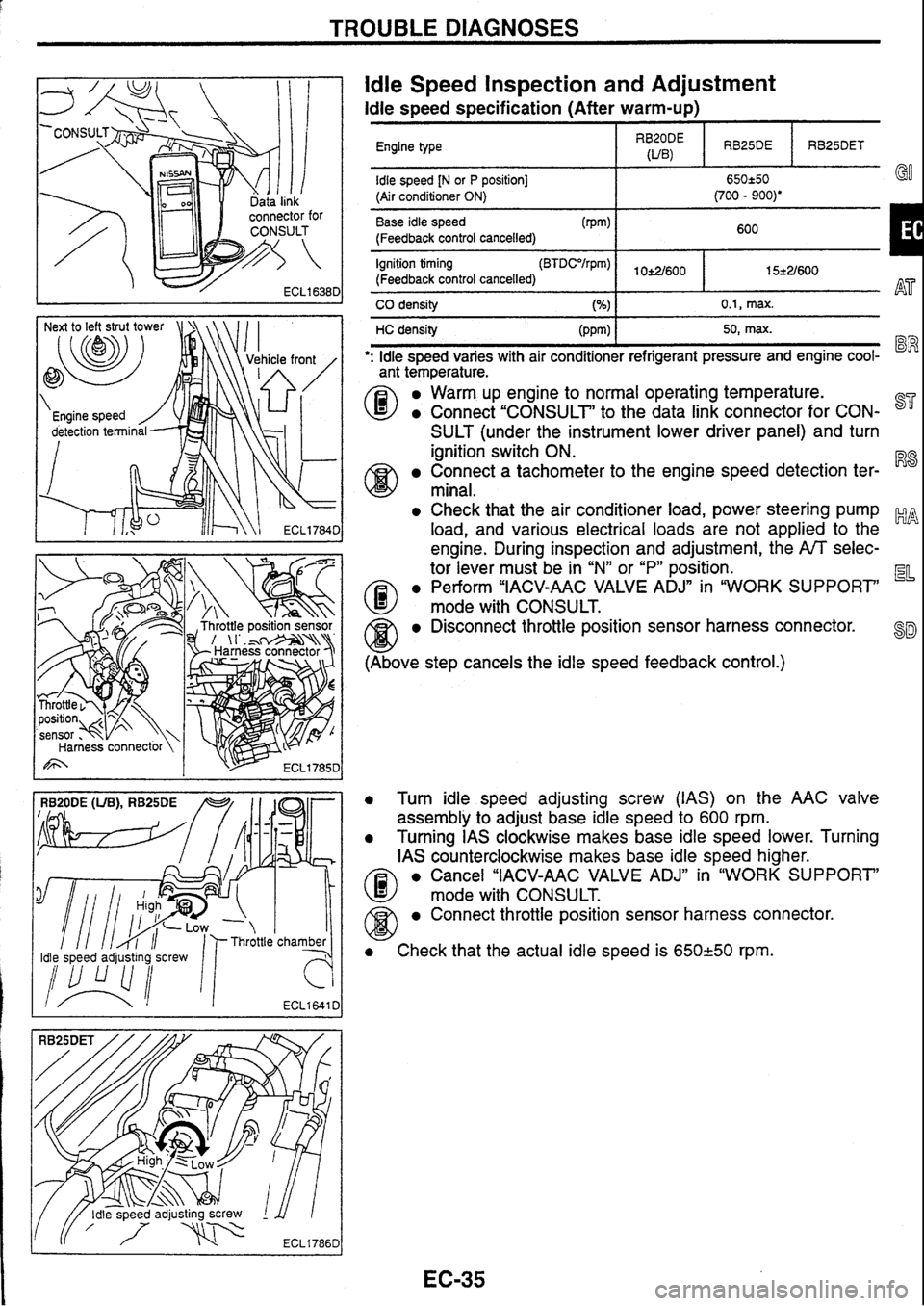
ldle Speed Inspection and Adjustment
ldle speed specification (After warm-up)
Engine type I RygE I RB25DE I RB25DET
Base idle speed (Pm)
(Feedback control cancelled) 600
I 1
idle speed [N or P position] (Air conditioner ON)
Ignition timing
(Feedback control cancelled) I 15*2/600
. . I I
650250 Go (700 - 900)'
CO density 0.1, max.
HC density 50, max.
': ldle speed varies with air conditioner refrigerant pressure and engine cool- "" "
ant temperature.
0
a Warm up engine to normal operating temperature.
a Connect "CONSULT' to the data link connector for CON- 87'
SULT (under the instrument lower driver panel) and turn
ignition switch ON.
Connect a tachometer to the engine speed detection ter- R8
minal.
a Check that the air conditioner load, power steering pump ~p, -4 load, and various electrical loads are not applied to the
engine. During inspection and adjustment, the
A/T selec-
tor lever must be in
"N"
or
"P"
position.
a Perform "IACV-AAC VALVE ADJn in "WORK SUPPORT EL
@ mode with CONSULS.
@ a Disconnect throttle position sensor harness connector. 8~
(Above step cancels the idle speed feedback control.)
0 Turn idle speed adjusting screw (IAS) on the AAC valve
assembly to adjust base idle speed to
600 rpm.
a Turning IAS clockwise makes base idle speed lower. Turning
IAS counterclockwise makes base idle speed higher.
a Cancel "IACV-AAC VALVE ADJ" in "WORK SUPPORT'
@ mode with CONSULT.
a Connect throttle position sensor harness connector.
a Check that the actual idle speed is 650-1-50 rpm.
Page 43 of 230

TROUBLE DlAGNOSES
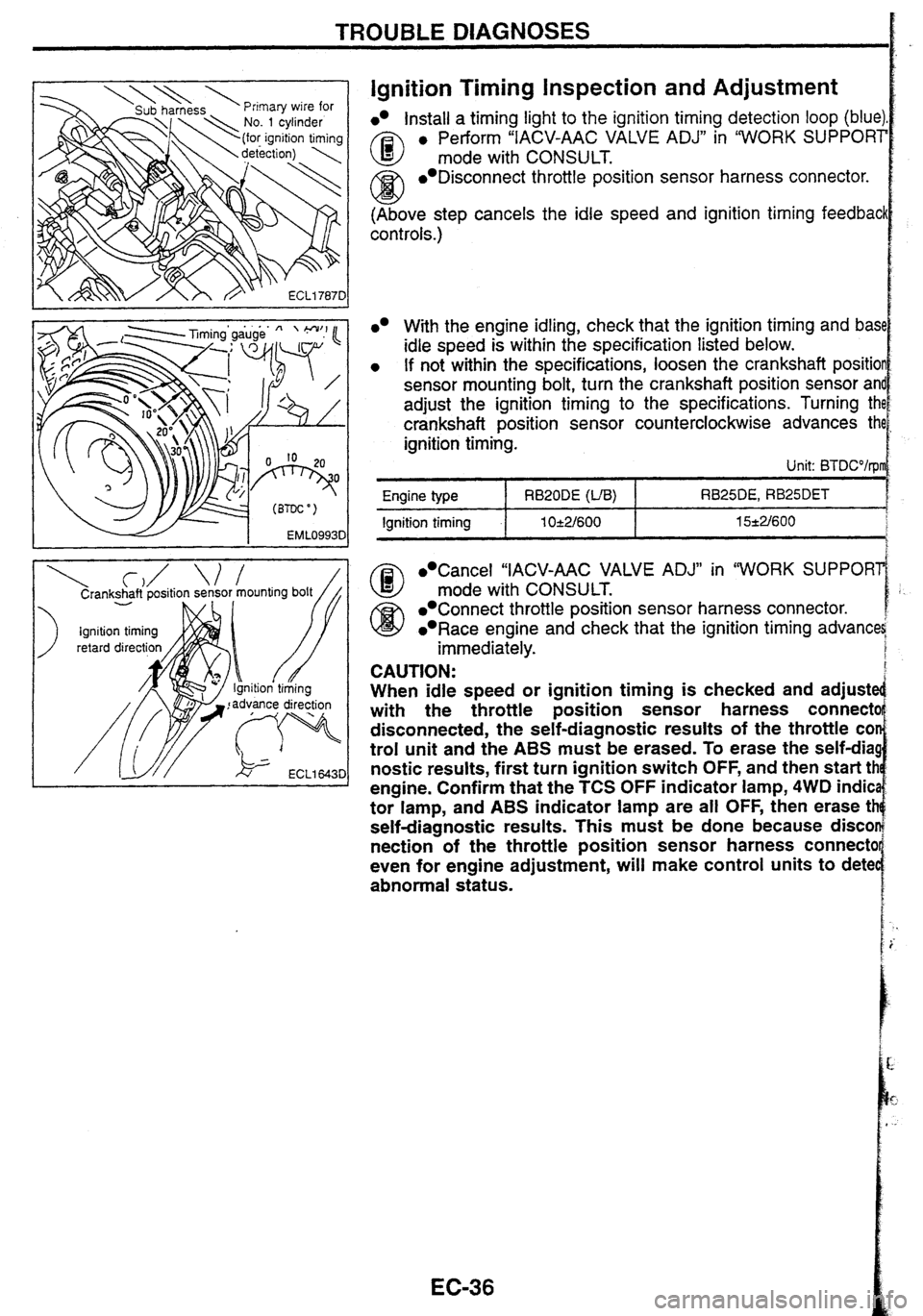
Ignition Timing inspection and Adjustment
lnstall a timing light to the ignition timing detection loop (blue)
A3 e Perform "IACV-AAC VALVE ADJ" in "WORK SUPPORT
mode with CONSULT.
/Ci3 Disconnect throttle position sensor harness connector.
w (Above step cancels the idle speed and ignition timing feedbacl
cont rots.)
Cancel "IACV-AAC VALVE ADJ" in "WORK SUPPORl
@ mode with CONSULT.
Connect throttle position sensor harness connector.
Race engine and check that the ignition timing advana
immediately.
With the engine idling, check that the ignition timing and bas1
idle speed is within the specification listed below.
If not within the specifications, loosen the crankshaft positio
sensor mounting bolt, turn the crankshaft position sensor
an
adjust the ignition timing to the specifications. Turning th
crankshaft position sensor counterclockwise advances th
ignition timing.
Unit: BTDCO/rpl
CAUTION:
When idle speed or ignition timing is checked and adjuste
with the throttle position sensor harness
connectc
disconnected, the self-diagnostic results of the throttle
COI
trol unit and the ABS must be erased. To erase the self-dia!
nostic
results, first turn ignition switch OFF, and then start tt
engine. Confirm that the
TCS OFF indicator lamp, 4WD indic
tor lamp, and
ABS indicator lamp are all OFF, then erase tt
self-diagnostic results. This must be done because disco
nection
of the throttle position sensor harness connectc
even for engine adjustment,
will make control units to dete
abnormal status.
RB25DE, RB25DET
15*2/600 Engine type
Ignition timing
RB20DE (VB)
1 O-e2/600
Page 157 of 230

FULLY AUTOMATIC AIR CONDITIONER
Trouble Diagnosis by Self-diagnosis Function
There are 5 steps in the self-diagnosis: to check for any sensor failure, and to check that a given control sig-
nal is transmitted to each output device.
Diagnosis
content
- - -
Diagnostic
item
i Step I I Step 2 - - - - - - - --
Each sensor check
Indicator lamp check
Display segments Ambient sensor
0 Indicator lamp In-vehicle sensor
lntake air tempera-
ture sensor
Sunload sensor Step
3
Each
actuator check
and reset check display for each
sen-
lntake door actuator
Air mix door actua-
tor Mode door actuator
lntake door actuator
Air mix door actua-
tor
Mode door actuator
Blower fan motor
Compressor
Air purifier (only
when connected)
Ambient sensor
In-vehicle sensor
lntake air tempera-
ture sensor
SELF-DIAGNOSIS OPERATION PROCEDURE R8
Switching to self-diagnosis mode
Turn the temperature adjustment dial all the way to the left.
Start the engine with the ignition switch from OFF position. Within 10 seconds, press and hold the OFF
switch for more than approx. 5 seconds, to start the self-diagnosis step 1.
Self-diagnosis completion EL
a Turn the ignition switch OFF.
Turn the AUTO switch ON.
Switching between self-diagnosis steps
Use the temperature adjustment dial to switch between self-diagnosis steps 1 to 5.
Temperature adjustment dial (turn clockwise): Step
1-5
Temperature adjustment dial (turn counterclockwise): Step
5- 1
a Refer to "SELF-DIAGNOSIS DISPLAY ITEM" for the diagnosis contents of each step.
Page 158 of 230

FULLY AUTOMATIC AIR CONDITIONER
Trouble Diagnosis
by Self-diagnosis Function
(Cont'd)
Step 3 AUTO SW: ON +
I
Step 1
(CW) Tum the temperature (CCW) Turn the temperature
adjustment dial. adjustment dial. I
IGN SW: OFF
AUTO SW: ON *
T
I Step 4 I AUTO SW: ON *
4 (CW) Turn the temperature (CCW) Turn the temperature
adjustment dial. adjustment dial. I
Step 2 IGN SW: OFF
AUTO SW: ON *
I
CW: Clockwise I CCW: Counterclockwise
Step 5 Detected temperature d~splay for each sensor IGN SW: OFF AUTO SW: ON
C : Each switch indicator lamp HAK0725D
SELF-DIAGNOSIS DISPLAY ITEM
Step 1 - Display segments and indicator lamp check
Check the controller switch indicator lamp and display segments.
Normal: The switch indicator lamp and display segments are illu-
minated.
Abnormal: Malfunctioning area will not be illuminated.
lllum~nated when a short- (T"e last digir ") circuit is detected.
the display code
the corresponding codes
Step 2 - Each sensor check
Display shows "2 in the step 2 mode, and then shows the judge-
ment result.
Check the data of each sensor inputted into the automatic ampli-
fier.
Normal: Display shows
"20.
Abnormal: The last digit of the display code flashes for a malfunc-
tioning sensor. At this time, if a short-circuit
is detected,
"AUTO is displayed. Furthermore, when there are more
than one malfunctioning sensor, the corresponding dis-
play codes flash twice starting with the smaller code.
The sunload sensor will judge an abnormality when there is
insufficient lighting (less than 5,000 lx) such as while being
placed indoor or during the evening.