heater NISSAN GT-R 1998 Service Manual
[x] Cancel search | Manufacturer: NISSAN, Model Year: 1998, Model line: GT-R, Model: NISSAN GT-R 1998Pages: 230, PDF Size: 12.66 MB
Page 9 of 230
ENGINE AND EMISSION CONTROL OVERALL SYSTEM
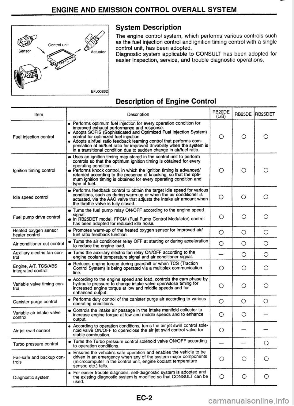
A 1 System Description
The engine control system, which performs various controls such
as the fuel injection control and ignition timing control with a single
control unit, has been adopted.
Diagnostic system applicable to
CONSULT has been adopted for
easier inspection, service, and trouble diagnostic operations.
Description of Engine Control
I
Description \,
Performs optimum fuel injection for every operation condition for
improved exhaust performance and response.
Adopts
SOFlS (Sophisticated and Optimized Fuel Injection System)
control for optimized fuel injection.
Adopts
airbuel ratio feedback
learning control that performs
com-
0
pensation of airfiuel ratio for improved drivability when the system is
in a transitional condiiion due to sudden change in
airfiuel ratro.
Uses an ignition timing map stored in the control unit to perform
controls so that the optimum ignition timing is obtained for every
operating condition.
Performs knock control, in which the ignition timing is advancedl
retarded according to the presence of knocking, so that the
opti- 0
mum i nition timing is obtained for every operating condition and
type
oPfue1.
Performs feedback control to obtain the target idle speed for various
conditions, such as during warm-up or when the air conditioner is
actuated, via the
AAC valve that adjusts the intake air amount when
O
the throttle valve is fully closed.
Turns the fuel pump relay OWOFF according to the engine speed
Fuel
injection control
Ignition timing control
Idle
speed
control
Fuel pump drive signal. In RB25DET model, FPCM (Fuel Pump Control Modulatoi) control O
has been adopted for reduced idle noise.
Heated oxygen sensor
heater control
Air conditioner cut control
Promotes warm-up of the heated oxygen sensor for improved air1
fuel ratio feedback function. 0
Tums the air conditioner relay OFF at starting or during acceleration to reduce the engine load. 0 -- Auxiliary electric fan con-
trol
Engine,
M, TCS,ABS integrated control
Tums the auxiliary electric fan relay ONIOFF according to the - engine coolant temperature signal and air conditioner signal.
Reduces engine toque during gearshift or when TCS (Traction
Control System) is being operated via a multiplex communication
lino 0
- -
Variable valve timing con-
trol According to the engine speed and load, controls the cam phase by
hydraulic pressure to change intake valve
open/close timing for
Increased engine torque at low and middle speeds and for
enhanced
out~ut.
I o I
Canister purge control air
intake valve control
Air
jet swirl control Performs duty
control of the canister purge air according to various ooeratina conditions.
0 -r-~ e-- ---
-
Controls the intake air passage in the intake manifold collector to
increase engine torque at low and middle speeds and to enhance
output. 0
According to operation conditions, turns the air jet swirl control sole-
noid valve ONIOFF to openlclose the air jet swirl control valve
for 0
pressure control
stable combustion.
Tums the Turbo pressure control solenoid valve ONIOFF according - to operation conditions.
Ensures the vehicle's safe operation and enables the vehicle
to be
Fail-safe and backup con-
trols
Diagnostic system driven
in an emergency when any of the system major components
(microcomputer in the control unit, engine coolant temperature
0
sensor, etc.) fails.
For easier trouble diagnosis, self-diagnostic system is adopted and
the existing diagnostic system is modified so that CONSULT can be
0 used.
Page 13 of 230
ENGINE AND EMISSION CONTROL OVERALL SYSTEM
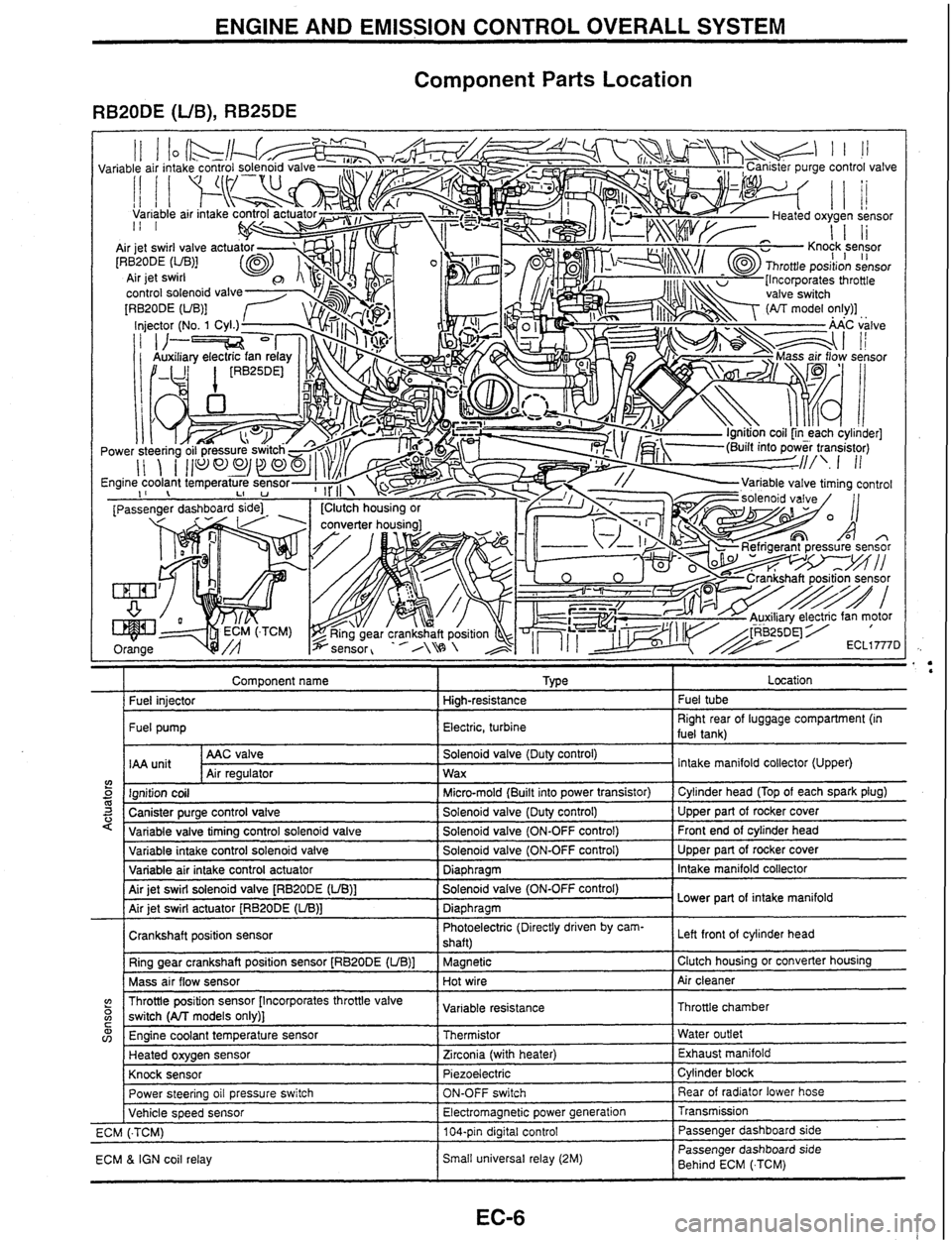
Component Parts Location
RB20DE (UB), RB25DE
Component name I Type I Location
I Fuel iniector I Hiah-resistance I Fuel tube
I Fuel pump I Electric, turbine I Right rear of luggage compartment (in
fuel tank)
AAC valve
IAA
unit Air reaulator
5 m 3 '
Solenoid valve (Duty control)
Wax
variable intake control solenoid valve
Variable air intake control actuator
Air jet swirl solenoid valve
[RBPODE (UB)]
Air jet swirl actuator
[RB20DE (LIB)]
Crankshaft position sensor Ring gear crankshaft position sensor
[RB20DE (UB)]
Mass air flow sensor Intake
manifold collector (Upper)
Ignition coil
Canister purge control valve
Variable valve tirnina control
solenoid valve
(? o C
Solenoid valve (ON-OFF control)
Diaphragm
Solenoid valve (ON-OFF control)
Diaphragm Photoelectric (Directly driven by cam-
shaft)
Magnetic
Hot wire
w v,
Micro-mold (Built into power transistor)
Solenoid valve (Duty control)
Solenoid valve (ON-OFF control) Upper part of rocker cover
Intake manifold collector
Lower part of intake manifold
Left front
of cylinder head
Clutch housing or converter housing
Air cleaner
Throttle position sensor [Incorporates throttle valve
switch
(All models only)]
Power steering oil pressure switch
Vehicle speed sensor
ECM
(.TCM)
ECM
& IGN coil relay Cylinder head
(Top of each spark plug)
Upper part of rocker cover
Front end of cylinder head
Engine coolant temperature sensor
Heated oxygen sensor
Knock sensor Variable
resistance
ON-OFF switch
Electromagnetic power generation
104-pin digital control
Small universal relay (2M) Throttle chamber
Thermistor
Zirconia (with heater)
Piezoelectric Rear of radiator lower hose
Transmission Passenger dashboard side
Passenger dashboard side
Behind ECM
(.TCM) Water
outlet
Exhaust manifold
Cylinder block
Page 14 of 230
ENGINE AND EMISSION CONTROL OVERALL SYSTEM
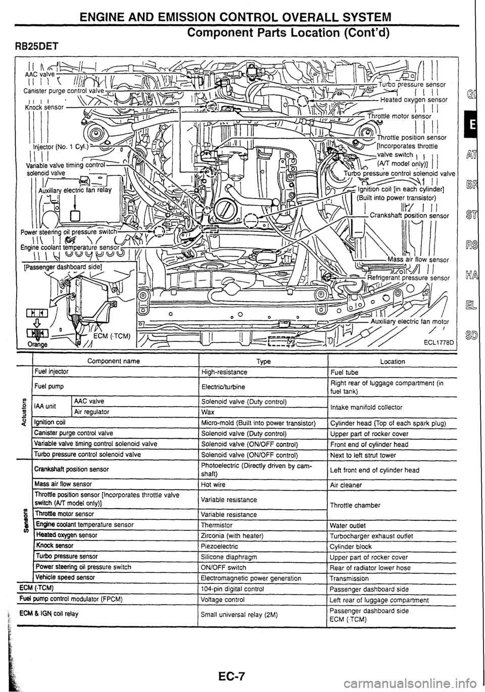
Component
Parts Location (Cont'd)
" . . ., . .7
Comoonent name I TVLE a r Fuel injector High-resistance
Fuel pump
Electriclturbine
5 I unit I AAC valve I Solenoid valve (Duty control)
S Air reoulator 1 wax -1 I " - . -.
4 Ignition coil I Micro-mold (Built into power transistor)
I Canister purge control valve I Solenoid valve (Dutv control) ---- - Variable valve timing control solenold valve I Solenold valve (ONtOFF control)
Turbo pressure control solenoid valve
I Solenoid valve (OMOFF control)
Crankshaft position sensor Photoelectric
(Directly driven by cam-
shaft)
Mass air flow sensor
Hot wire
Throttle position sensor [Incorporates throttle valve
switch
(AlT model only)] Variable
resistance
Throttle motor sensor
09 Variable resistance
5 Engine coolant temperature sensor Thermistor V) Heated oxygen sensor
Zirconia (with heater)
Knock sensor Piezoelectric
Turbo pressure sensor Silicone diaphragm
Power
steering oil pressure switch
ONJOFF switch
( Vehicle speed sensor
Electromagnetic power generation
ECM
(.TCM) 104-pin digital control
Fuel pump control modulator (FPCM)
Voltage control
1 ECM L IGN co~l relay Small un~versal relay (2M) P t
.
Fuel tube
Right rear of luggage compartment (in
fuel tank)
Intake manifold collector
Cvlinder head
UOD of each soark olua)
Upper part of rocker cover
Front end of cylinder head
Next to left strut tower
Left front end of cylinder head
Air cleaner
Throttle chamber
Water outlet
Turbocharaer exhaust outlet
Cylinder
block
Upper part of rocker cover
Rear of radiator lower hose
Transmission
Passenger dashboard side
Left rear of
luaaaae comoartment
-- Passenger dashboard s~de
ECM ( TCM)
Page 21 of 230
ENGINE AND EMISSION CONTROL OVERALL SYSTEM
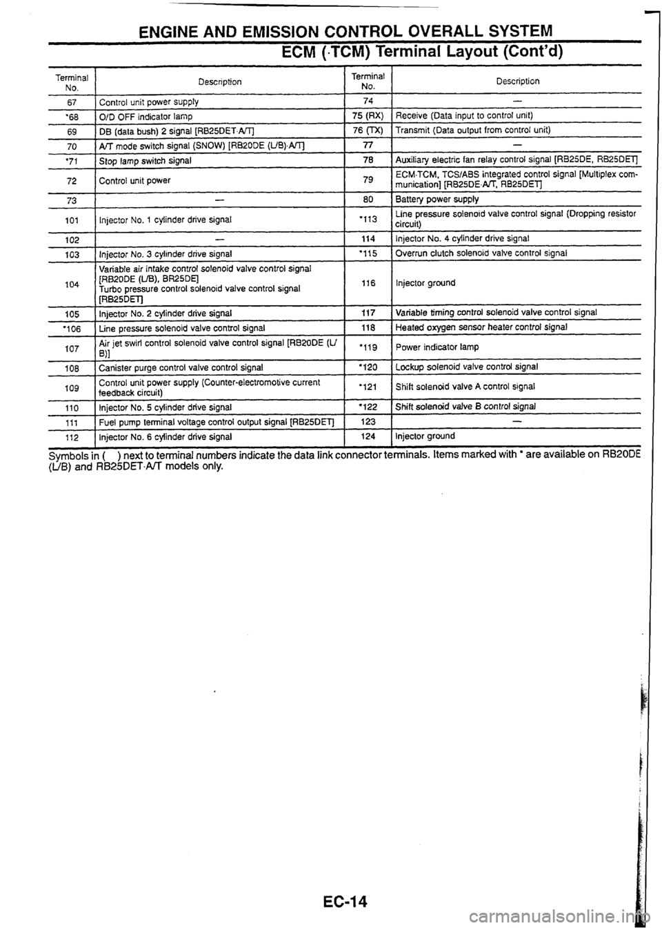
ECM (-TCM) Terminal Layout (Cont'd)
Terminal
No.
67
'68
69 Description
70
'71
72 I
Control unit power supply
O/D OFF indicator
lamp
DB (data bush) 2 signal
[RB25DET.AIT]
73
101
104
1 [RB~ODE (LIB), BR25DEl -
Turbo oressure control solenoid valve control signal I I16 I lnjector ground
Terminal
No.
AK mode switch signal (SNOW) [RB20DE (UB).AIT]
Stop lamp switch signal
Control unit power
102
103 Description
74
75 (RX)
76
(TX)
1 I . .
-
Receive (Data input to control unit)
Transmit (Data output from control unit)
77
78
79
-
Injector No. 3 cylinder drive signal
Variable air intake control solenoid valve control
sianal
105
'106
107
-
Auxiliary electric fan relay control signal [RB25DE, RB25DElJ
ECM.TCM. TCSIABS integrated control signal [Multiplex
com-
munication] [RB25DENT. RB25DEl
Battery power supply
Line pressure solenoid valve control signal (Dropping resistor
circuit)
-
lnjector No. 1 cylinder drive signal
1 08
log
80
"I3
114
'1 15
[RB~~DET]
Injector No. 2 cylinder drive signal
Line pressure solenoid valve control signal
Air jet swirl control solenoid valve control signal
[RB20DE
(U ,\I
110 111
112 Injector No.
4 cylinder
drive signal
Overrun clutch solenoid valve control signal
"11
Canister purge control valve control signal
Control unit power supply (Counter-electromotive current
feedback
circuit) 11
7
118
.119
Symbols
in ( ) next to terminal numbers indicate the data link connector terminals. Items marked with ' are available on RB20DE (UB) and R825DET.All models only.
Injector No. 5 cylinder drive signal
Fuel pump terminal voltage control output signal
[RB25DET]
Injector No. 6 cylinder drive signal Variable
timing control solenoid valve control signal
Heated oxygen sensor heater control signal
Power indicator lamp
'120
'121 Lockup solenoid valve control signal
Shift solenoid valve
A control signal I '122
123 124 Shift solenoid valve B control signal
-
Injector ground
Page 147 of 230

HEATER &
AIR CONDITIONER
CONTENTS
HA SECTION
............................................................. COOLER CYCLE 2
Deodorizing Clean Filter .............................................. 2
FULLY AUTOMATIC AIR CONDITIONER ...................... 3
System Description ...................................................... 3
Component Parts Location .......................................... 4
Circuit Diagram ............................................................ 5
Automatic Amplifier Input /Output Signal
Specifications
.............................................................. .6
GI
EG
Performance Test ......................................................... 8 Rs
Trouble Diagnosis by Gauge Pressure ..................... 10
.......... Trouble Diagnosis by Self-diagnosis Function 11
Magnet Clutch System Check ................................... 15
Blower Fan Motor System Check 15
I ..............................
Actuator System Check ............................................. 16 EL
Trouble Diagnosis for Each Symptom ....................... 17
Component Parts Inspection ..................................... 18 SD
Page 163 of 230
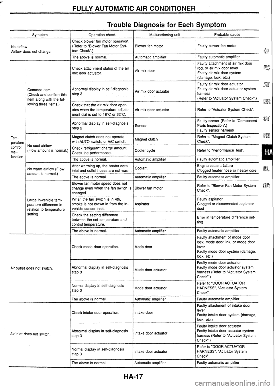
FULLY AUTOMATIC AIR CONDITIONER
Symptom
Trouble Diagnosis for Each Symptom
No airflow
Airflow does not change. Operation check
Check blower fan motor operation. (Refer to "Blower Fan Motor Sys-
tem Check".)
The above is normal.
I Automatic amolifier 1 Faultv automatic amplifier
Faulty attachment of air mix door
rod, or air mix door lever
Faulty air mix door system
ElG
(damage, lock, etc.)
Malfunctioning unit
Blower fan motor Probable cause
Faulty blower fan motor
Check attachment status of the air
mix door actuator.
Common item (Check and confirm this
item along with the fol-
lowing three items.)
Air mix door
Abnormal display in self-diagnosis
step
3
Check that the air mix door oper-
ates when the temperature
adjust-
ment dial is set to
18OC or 32°C.
Faulty sensor (Refer to 'Component a
Parts Inspection".)
Faulty sensor harness
Air
mix door actuator
Air mix door actuator
Abnormal display in self-diagnosis
step 2
Magnet clutch does not operate
Magnet clutch Refer
to 'Magnet Clutch System R8
with AUTO switch, or A/C switch. Check".
I Faulty
air mix door actuator
Faulty air mix door actuator system AT
hamess
(Refer to "Actuator System Check".)
BW
Refer to "Actuator System Check".
@'i?
Sensor
Tem- perature
control mal-
function No
cool airflow
(Flow amount is normal.)
ngeranr
cnarge
amounr.
( Cooler cycle 2 ~erformance. I Refer to 'Performance Test". I
The above is normal. I Automatic amolifier 1 Faulty automatic amplifier I
After warming up, the heater core
inlet and outlet hoses are not warm. 1 Coolant I
Engine coolant failure
Clogged heater hose or heater core
No warm airflow
(Flow
amount is normal.)
The above is normal. Automatic amplifier
1 Faulty automatic amplifier
Blower fan motor speed does not
change even when the fan switch is Blower fan motor
changed. Refer
to "Blower Fan Motor System
Check".
I
When the fan switch is in 4th, Faulty aspirator
smoke is not drawn in from the
in-
Aspirator Clogged
or disconnected aspirator
vehicle sensor inlet. duct
Large
in-vehicle tem-
perature difference in
relation to temperature
setting Check the setting difference
between the set temperature and
control temperature. Error
in temperature difference set-
ting
- The above isnormal.- Automatic amplifier Faulty automatic amplifier
Faulty attachment of mode door
lock, mode door link, or mode door
Check mode door operation. Mode door lever
Faulty mode door system (damage,
lock, etc.)
Faulty mode door actuator
Abnormal display in self-diagnosis Faulty mode door actuator system
step
3 Mode door actuator
harness (Refer to "Actuator System
Check".)
Air
outlet does not switch.
Normal display in self-diagnosis
Mode door actuator
step
3
Refer to "DOOR ACTUATOR
HARNESS", "Actuator System
Check".
The above is normal.
I Automatic amplifier I Faulty automatic amplifier - - I I Faulty attachment of intake door
Check intake door operation. lntake
door lever
Faulty intake door system (damage,
lock, etc.)
~aulG intake door actuator
Faulty intake door actuator system
hamess (Refer to "Actuator System
Check".)
Abnormal
display in self-diagnosis
door step 3 Air inlet does fiot switch.
Normal display in self-diagnosis
lntake door actuator
step
3
Refer to "DOOR ACTUATOR
HARNESS", "Actuator System
Check".
I I The above is normal. I Automatic amplifier I Faulty automatic amplifier
Page 166 of 230
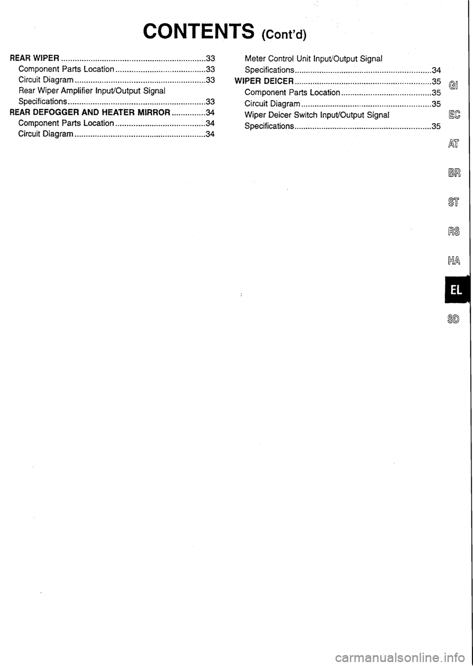
CONTENTS (cm9d)
REAR WIPER ................................................................ 33 Meter Control Unit InpuVOutput Signal
Component
Parts Location ....................................... .33 Specifications -34 ............................................................
Circuit Diagram .......................................................... 33 WIPER DEICER ............................................................. 35
Rear Wiper Amplifier
Input/Output
Signal Component Parts Location
.35 @I .......................................
Specifications ............................................................ .33 Circuit Diagram 35 ..........................................................
REAR DEFOGGER AND HEATER MIRROR ............... 34 Wiper Deicer Switch InpuVOutput Signal
Component Parts Location ..34 Specifications.. 35 EG ...................................... ........................................................... .......................................................... Circuit Diagram 34
Page 199 of 230
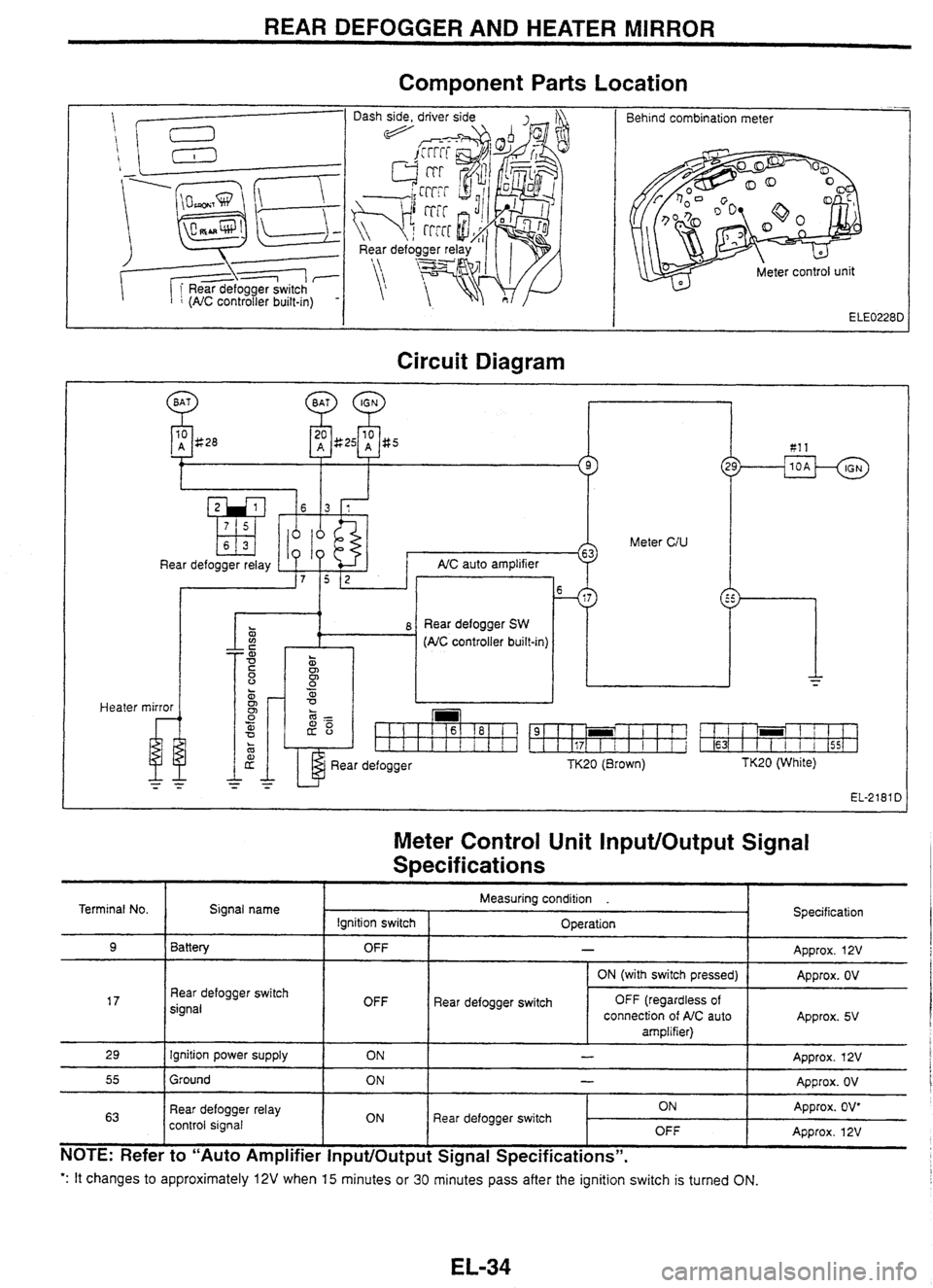
REAR DEFOGGER AND HEATER MIRROR
Component
Parts Location
-- Behind combination meter
Circuit Diagram
Heater
10 A g28 81 1
Meter CIU
Rear defogger relay AIC auto ampl~f~er
. 0
z i 8 Rear defogger SW a (AC controller built-m)
mirror
u
Rear defogger TK20 (Brown) TK20 (White)
EL-2181 D
Meter Control Unit InputlOutput Signal
S~ecif ications
': It changes to approximately 12V when 15 minutes or 30 minutes pass after the ignition switch is turned ON.
Terminal No.
9
17
29
55
63
NOTE: Refer to "Auto Amplifier InputlOutput Signal Specifications".
Signal name
Battery
Rear defogger switch
signal
Ignition power supply
Ground
Rear defogger relay
control signal Specification
Approx.
12V
Approx. OV
Approx. 5V
Approx. 12V
Approx. OV
Approx. OV*
Approx. 12V
Measuring condition .
Ignition switch OFF
OFF ON
ON
ON Operation
-
Rear
defogger switch ON (with switch
pressed)
OFF (regardless of
connection of AIC auto
amplifier)
-
-
Rear defogger switch ON OFF