width NISSAN GT-R 1998 Service Manual
[x] Cancel search | Manufacturer: NISSAN, Model Year: 1998, Model line: GT-R, Model: NISSAN GT-R 1998Pages: 230, PDF Size: 12.66 MB
Page 22 of 230

TROUBLE DIAGNOSES --- - - - -- -- - -
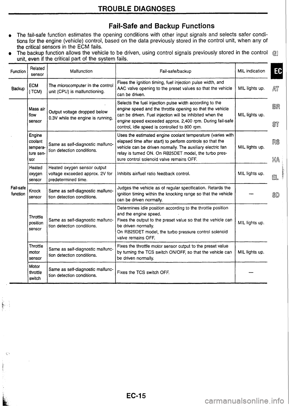
Fail-safe and Backup Functions
0 The fail-safe function estimates the opening conditions with other input signals and selects safer condi-
tions for the engine (vehicle) control, based on the data previously stored in the control unit, when any of
the critical sensors in the
ECM fails.
The backup function allows the vehicle to be driven, using control signals previously stored in the control G]
unit, even if the critical part of the system fails.
MIL indication
I
Related
sensor
Function
Backup Malfunction
Fail-safehacku p
Fixes the ignition timing, fuel injection pulse width, and
AAC valve opening to the preset values so that the vehicle
can be driven.
ECM
(-TCM)
Mass air
flow
sensor
Engine
coolant
tempera- ture sen-
sor The
microcomputer in the control
unit (CPU) is malfunctioning. MIL lights
up. A'
-- --
Selects the fuel injection pulse width according to the
engine speed and the throttle opening so that the vehicle
can be driven. Fuel injection will be inhibited when the
engine speed exceeded approx.
2,400 rpm. During fail-safe
control, idle speed is controlled to 800
rpm.
Uses the estimated engine coolant temperature (varies with
elapsed time after start) to perform controls so that the
vehicle can be driven normally. The auxiliary electric fan
relay is turned ON. On
RB25DET
model, the turbo pres-
sure control solenoid valve remains OFF.
%R
MIL lights up.
ST
Output voltage dropped below
0.3V while the engine is running.
MIL lights up.
R8 Same as self-diagnostic malfunc-
tion detection conditions.
Heated
owen
sensor Heated oxygen sensor output
voltage exceeded approx.
2V for
predetermined time.
Same as self-diagnostic malfunc-
tion detection conditions. MIL
lights up. d d Inhibits aidfuel ratio feedback control.
Judges the vehicle as of regular specification. Retards the
ignition timing within the knocking range so that the vehicle
can be driven normally.
Determines idle position according to the throttle position
and the engine speed.
Fixes the output to the preset value so that the vehicle can
be driven normally.
On
RB25DET model, the turbo pressure control solenoid
valve remains OFF.
Fail-safe
function Knock
sensor
Throttle position
sensor Same
as self-diagnostic malfunc-
tion detection conditions. MIL
lights up.
Throttle motor
sensor
--
Fixes the throttle motor sensor output to the preset value
by turning the TCS switch
ONIOFF, so that the vehicle can
Same
as self-diagnostic malfunc-
tion detection conditions. MIL
lights up.
be driven normally.
Motor
throttle
switch Same
as
self-diag
nostic
malfunc-
tion detection conditions. Fixes the
TCS switch OFF.
t.. -
Page 30 of 230
![NISSAN GT-R 1998 Service Manual
TROUBLE DIAGNOSES .
CONSULT (Contd)
Monitored item
[Unit] signals Description
Remarks
INJ
PULSE [msec]
I
When the engine is stopped, a certain
computed value is indicated. lndicates NISSAN GT-R 1998 Service Manual
TROUBLE DIAGNOSES .
CONSULT (Contd)
Monitored item
[Unit] signals Description
Remarks
INJ
PULSE [msec]
I
When the engine is stopped, a certain
computed value is indicated. lndicates](/img/5/57354/w960_57354-29.png)
TROUBLE DIAGNOSES .
CONSULT (Cont'd)
Monitored item
[Unit] signals Description
Remarks
INJ
PULSE [msec]
I
When the engine is stopped, a certain
computed value is indicated. lndicates the actual fuel injection pulse
width compensated by ECM according to
the input
siqnals.
IGN TIMING [BTDC]
I lo
lndicates the ignition timing computed by ECM according to the input signals. When the engine is stopped, a certain
value is indicated.
IACV-AACN
I%]
I lo
lndicates IACV-AACN control value com-
puted by ECM according to the input sig-
nals.
PURG VOL CN
[ONIOFF dutyj lndicates the EVAP canister purge vol-
ume control valve computed by the ECM according to the input signals. The opening becomes larger as the
value increases.
AIF
ALPHA [%]
- The mean value of the air-fuel ratio feed-
back correction factor per cycle is indi-
cated. -- - When the engine is stopped, a certain
value is indicated.
This data also includes the data for the
air-fuel ratio learning control.
AIR COND
RLY [ONIOFF] The air conditioner relay control condition
(determined by ECM according to the
input signal) is indicated.
-- - - Indicates the fuel pump relay control con-
dition determined by ECM according to
the input signals.
The control condition of the intake valve
timing control solenoid valve is indicated.
ON
... Intake valve timing control is oper-
ating. OFF
... lntake valve timing control is not
operating.
VlAS
SN [ONIOFF] RB20DE (UB), RB25DE
Control conditions computed by ECM Solenoid valve activated: ON Solenoid valve not activated: OFF
SWRL CONT SN
[ON/OFF]
0 RB20DE (UB)
COOLING FAN
[HVLOW/O FF] RB25DE, RB25DET
The control condition of the cooling fan
(determined by ECM according to the
input signal) is indicated.
HI
... High speed operation LOW ... Low speed operation
OFF ... Stop
TURBO CONT
SN 0 RB25DET Control conditions computed by ECM
Solenoid valve activated: ON Solenoid valve not activated: OFF
PD PRESSURE
SENSOR M Refrigerant pressure sensor output volt-
age Approx. 0.36V min.
(Varies with air conditioner refrigerant
pressure)
, VOLTAGE Voltage measured by the voltage probe.
Pulse width, frequency or duty cycle
measured by the pulse probe. Only "#" is displayed if item is unable to
be measured.
r Figures with "#"s are temporary ones.
They are the same figures as an actual
piece of data which was just previously
measured.
Page 68 of 230

TROUBLE DIAGNOSES
n t
\-Test port for "D", "2", and "1" positions
I 'Test port for "I?" position I
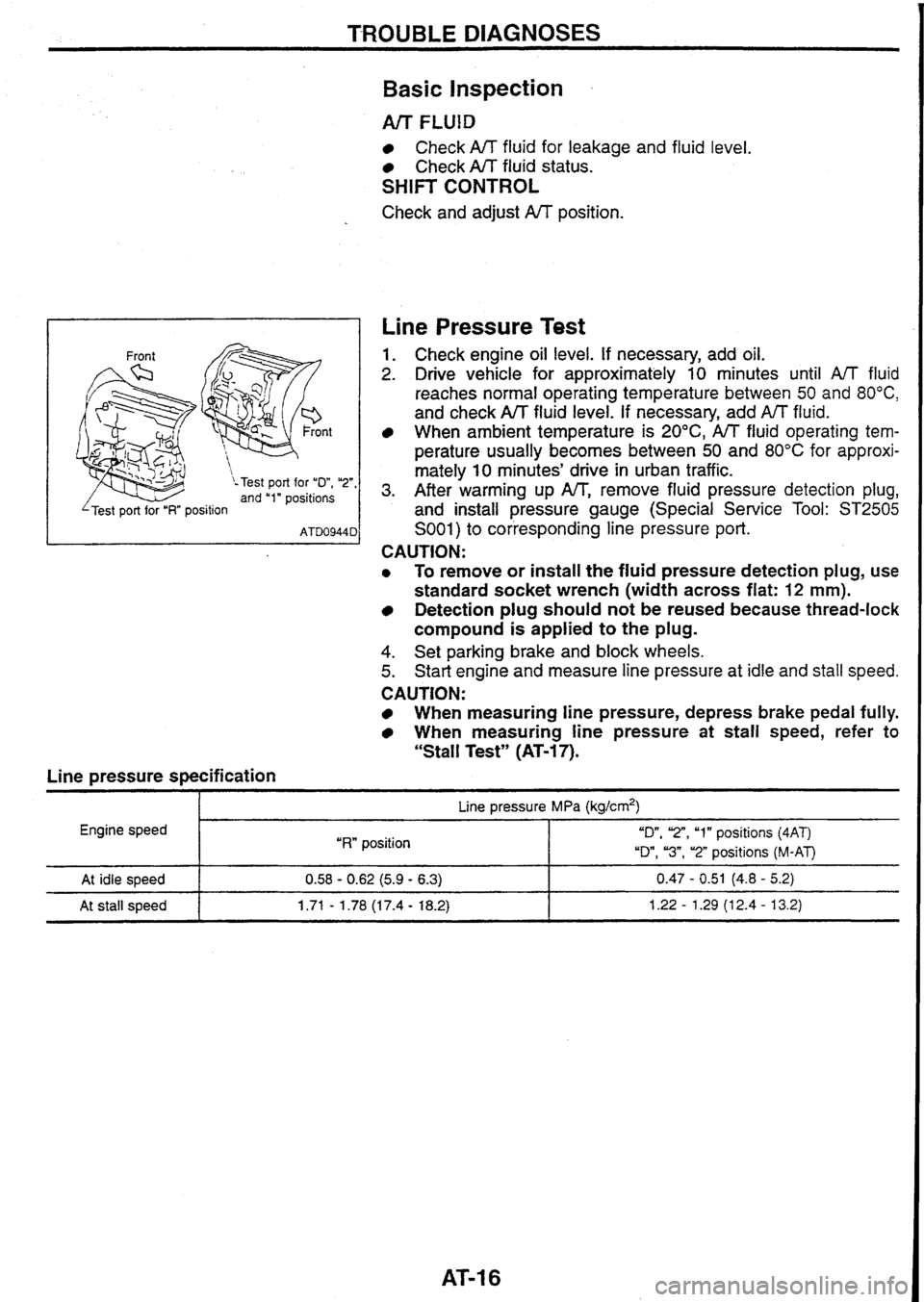
Line pressure specification
Basic Inspection
Arr FLUlD
Check A/T fluid for leakage and fluid level.
Check A/T fluid status.
SHIFT CONTROL
Check and adjust A/T position.
Line Pressure Test
1. Check engine oil level. If necessary, add oil.
2. Drive vehicle for approximately 10 minutes until A/T fluid
reaches normal operating temperature between
50 and 80°C,
and check A/T fluid level. If necessary, add fluid.
When
ambient temperature is 20°C, A/T fluid operating tem-
perature
usually becomes between 50 and 80°C for approxi-
mately
10 minutes' drive in urban traffic.
3. After warming up IW', remove fluid pressure detection plug,
and install pressure gauge (Special Service Tool:
ST2505
S001) to corresponding line pressure port.
CAUTION:
0 To remove or install the fluid pressure detection plug, use
standard socket wrench (width across flat:
12 mm).
Detection plug should not be reused because thread-lock
compound is applied
to the plug.
4. Set parking brake and block wheels.
5. Start engine and measure line pressure at idle and stall speed.
CAUTION:
When measuring line pressure, depress brake pedal fully.
When measuring line pressure at stall speed, refer to
"Stall Test" (AT-17).
I p- Line pressure MPa (kg/crn2)
Engine speed
I "RW position "On, 'Z", "1" positions (4AT)
"Dm,
"3", "2" positions (M-AT)
At idle speed
At stall speed 0.58 - 0.62 (5.9 - 6.3) 0.47 - 0.51 (4.8 - 5.2)
1.71
- 1.78 (1 7.4 - 18.2) 1.22 - 1.29 (1 2.4 - 13.2)
Page 90 of 230

ANTI-LOCK BRAKE SYSTEM
CONSULT (Cont'd)
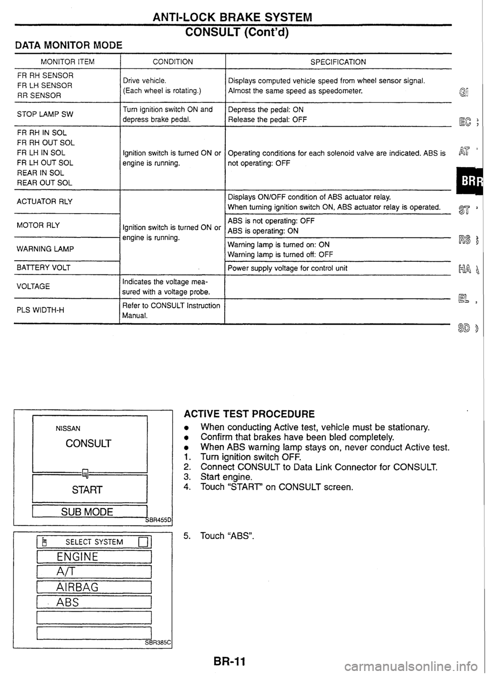
DATA MONITOR MODE
MONITOR ITEM I CONDITION
FR RH SENSOR
FR
LH SENSOR
RR SENSOR Drive vehicle.
(Each wheel is rotating.)
STOP LAMP SW Turn
ignition switch ON and
depress brake pedal.
FR RH
IN SOL
FR RH OUT SOL
FR
LH IN SOL
FR LH OUT SOL
REAR IN SOL
REAR OUT SOL Ignition
switch is turned ON or
engine is running.
ACTUATOR RLY
MOTOR RLY
Ignition switch is turned ON or
engine is running.
WARNING LAMP
BATTERY VOLT
I
VOLTAGE Indicates
the voltage mea-
sured with a voltage probe.
PLS WIDTH-H
I
Refer to CONSULT Instruction
Manual.
NlSSAN
CONSULT
START I --
1 SUB MODE BR455C
$ SELECT SYSTEM 0-
ENGINE
A/T
I - ABS I
SPECIFICATION
Displays computed vehicle speed from wheel sensor signal.
Almost the same speed as speedometer.
Depress the pedal: ON
Release the pedal: OFF
EC ;
Operating conditions for each solenoid valve are indicated. ABS is AT '
not operating: OFF
Displays ON/OFF condition of ABS actuator relay.
When turning ignition switch ON,
ABS actuator relay
is operated. 2
ABS is not operating: OFF
ABS
is operating: ON
Warning lamp is turned on: ON
R8 $
Warning lamp is turned off: OFF
Power supply voltage for control unit
~~~~
ACTIVE TEST PROCEDURE
When conducting Active test, vehicle must be stationary.
Confirm that brakes have been bled completely.
When ABS warning lamp stays on, never conduct Active test.
Turn ignition switch OFF.
Connect CONSULT to Data Link Connector for CONSULT.
Start engine.
Touch "START' on CONSULT screen.
Touch
"ABS".
Page 118 of 230

TCS/ABS SYSTEM
CONSULT for Throttle Control Unit Control
System (Cont'd)
DATA MONITOR MODE -- -
I Select monitor item
Display
I I
THRTL POS SEN [~l l o I n
I All signals
THRTL OPENING
lo] 1 0 I
Selection
from menu
THRTL POS SE2
MI 0 1;
THRL2 OPENING rOl / 0
BATTERY VOLT MI 0 I A
TH OPEN SIG ims]/ 0 I A
TH MOTOR DUTY I"/.] I 0 I A
CLOSED THUSW [ONIOFF]
NEUT POSl SW [ONIOFF]
START SIGNAL
[ONIOFF]
TH OPEN CONT
["I
TCS SIGNAL [ONIOFF] / OIa
TCS FLAG
0
0
0
0
A
A
A
A
TH CLSD LRN
PoNwEqI 0 / A
COMM COND [ONIOFFJ
VOLTAGE
PI I I A
0
Remarks
A
PULSE [ms, Hz, %I
Dispiays throttle position sensor signal voltage.
Displays throttle angle computed based on throttle position
EG
sensor signal voltage.
Displays throttle motor sensor signal voltage.
AT
-
Displays throttle motor angle computed based on throttle
motor sensor signal voltage.
Displays the battery voltage for the control unit.
h
Displays the pulse width of the throttle motor target angle
signal from the
TCSIABS control unit.
lndicates the switch status (ONIOFF) based on the throttle
position sensor signal.
lndicates the switch status (ONIOFF) based on the
parW
neutral position switch signal. lndicates the status (ONIOFF) based on the starter signal.
Displays the throttle motor control target computed by the
control unit based on each input signal.
lndicates the throttle motor drive duty.
lndicates the throttle motor relay status
(ON/OFF).
lndicates ON when the throttle motor angle reaches a
specified
iower limit.
lndicates "VALID" when throttle motor target angle signal is
received from the
TCS/ABS control unit and the throttle
control unit closes the throttle motor.
lndicates the condition of the communication between
TCS/
ABS control unit and throttle control unit. Normally ON is
indicated, and OFF is shown when there is failure.
lndicates
if the throttle motor has been fully closed before.
"DONE" is indicated when it has, and
"YET" is shown when
it has not yet.
lndicates the voltage measured with a voltage probe.
lndicates the pulse measured with a pulse probe.
If it cannot be measured,
"%" is shown on the display. The
%" mark is also shown to the left of the final data until the
measuring result is output.
I ACTIVE TEST PROCEDURE
1. Turn ignition switch OFF.
2. Connect CONSULT connector to data link connector for CON-
S U LT.
3. Turn ignition switch ON.
4. Touch "START" on CONSULT screen.
5. Touch "THROTTLE CONTROL" on CONSULT screen.