parking brake NISSAN GT-R 1998 Service Manual
[x] Cancel search | Manufacturer: NISSAN, Model Year: 1998, Model line: GT-R, Model: NISSAN GT-R 1998Pages: 230, PDF Size: 12.66 MB
Page 68 of 230

TROUBLE DIAGNOSES
n t
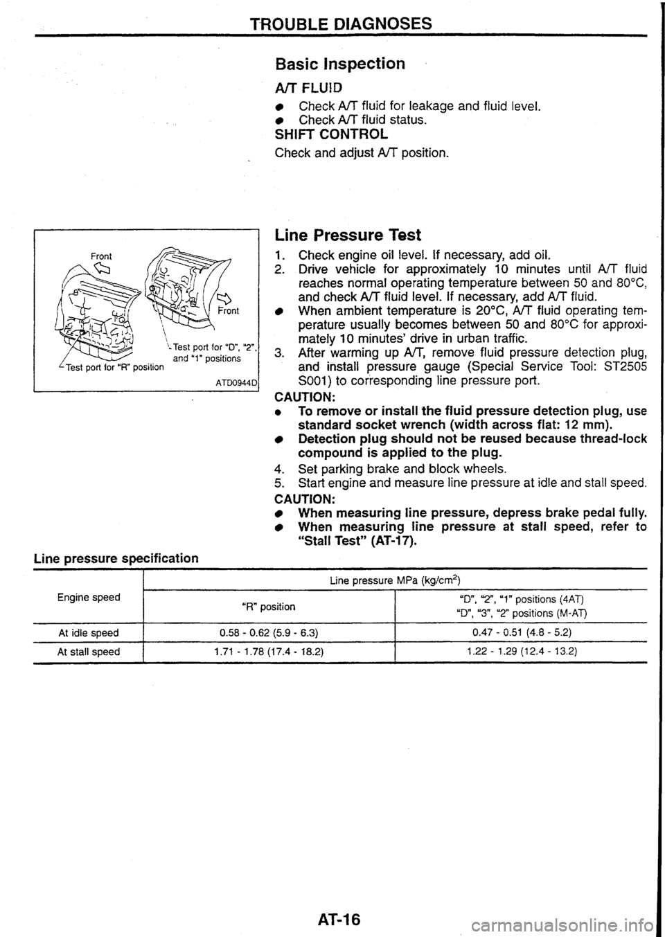
\-Test port for "D", "2", and "1" positions
I 'Test port for "I?" position I
Line pressure specification
Basic Inspection
Arr FLUlD
Check A/T fluid for leakage and fluid level.
Check A/T fluid status.
SHIFT CONTROL
Check and adjust A/T position.
Line Pressure Test
1. Check engine oil level. If necessary, add oil.
2. Drive vehicle for approximately 10 minutes until A/T fluid
reaches normal operating temperature between
50 and 80°C,
and check A/T fluid level. If necessary, add fluid.
When
ambient temperature is 20°C, A/T fluid operating tem-
perature
usually becomes between 50 and 80°C for approxi-
mately
10 minutes' drive in urban traffic.
3. After warming up IW', remove fluid pressure detection plug,
and install pressure gauge (Special Service Tool:
ST2505
S001) to corresponding line pressure port.
CAUTION:
0 To remove or install the fluid pressure detection plug, use
standard socket wrench (width across flat:
12 mm).
Detection plug should not be reused because thread-lock
compound is applied
to the plug.
4. Set parking brake and block wheels.
5. Start engine and measure line pressure at idle and stall speed.
CAUTION:
When measuring line pressure, depress brake pedal fully.
When measuring line pressure at stall speed, refer to
"Stall Test" (AT-17).
I p- Line pressure MPa (kg/crn2)
Engine speed
I "RW position "On, 'Z", "1" positions (4AT)
"Dm,
"3", "2" positions (M-AT)
At idle speed
At stall speed 0.58 - 0.62 (5.9 - 6.3) 0.47 - 0.51 (4.8 - 5.2)
1.71
- 1.78 (1 7.4 - 18.2) 1.22 - 1.29 (1 2.4 - 13.2)
Page 69 of 230

TROUBLE DIAGNOSES
Line Pressure Test (Cont'd)
JUDGEMENT OF LINE PRESSURE TEST
At idle
speed
At stall
speed Judgement
Line pressure is low in all
positions.
Line pressure is low in par-
ticular position.
Line pressure is
high.
Line pressure increase is
poorer than that measured at
idle speed.
Line pressure increases but
does not reach specification.
Line pressure is low in par-
ticular position. Possible
causes
Pressure supply system malfunction or low oil pump output
Examples:
0 Oil pump wear
Control piston damage
Pressure regulator valve or plug sticking, and weak spring
Fluid pressure leakage between oil strainer and pressure regulator valve through oil Eg
Pump
Low idle speed
After line pressure is supplied from manual valve, fluid pressure may leak between devices
or circuits of corresponding position.
1
Malfunctions of sensors or pressure regulation function. El
Examples:
Misadjustment of throttle position sensor
PJT fluid temperature sensor damaged ST
Poor operation of line pressure solenoid (stuck with OFF status, clogged filter, or open
harness)
Pressure modifier valve sticking F%
Pressure regulator valve or plug sticking
Malfunctions of sensors or pressure regulation function
Examples:
EILA
Misadjustment of throttle position sensor
TCM, ECM.TCM damaged la
Poor operation of line pressure solenoid (stuck or shorted with ON status)
Pressure regulator valve and plug sticking
Pressure modifier valve sticking
sf$
Pilot valve sticking and pilot filter clogged
Malfunctions of pressure supply system, sensors, or pressure regulation function
Examples:
Misadjustment of throttle position sensor
Control piston damage
Poor operation of line pressure solenoid, and filter sticking or clogged
Pressure regulator valve and plug sticking
Pressure modifier valve sticking
Pilot valve sticking and pilot filter clogged
After line pressure is supplied from manual valve, fluid pressure
may leak between devices
or circuits of corresponding position.
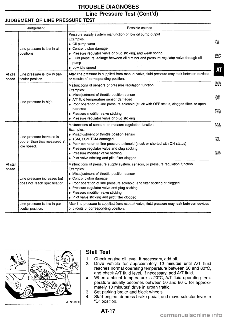
Stall Test
1. Check engine oil level. If necessary, add oil.
2. Drive vehicle for approximately 10 minutes until A/T fluid
reaches normal operating temperature between
50 and 80°C,
and check A/T fluid level. If necessary, add AfT fluid.
When ambient temperature is
20°C,
A/T fluid operating tem-
perature usually becomes between 50 and
80°C for approxi-
mately
10 minutes' drive in urban traffic.
3. Set parking brake and block wheels.
4. Statt engine, depress brake pedal, and move selector lever to
"D" position.
Page 77 of 230

TROUBLE DIAGNOSES
Symptom Chart
Sharp shock in Engine brake
applied
Shifting
Malfunctions
Slip
(Racing)
hifting
.- erator pedal
Shifting
Shifting
inspection item
Fluid level and status
Control linkage
PNP switch (short/open circuit)
Throttle ~osition sensor (installed)
I Vehicle weed sensor
I Enaine meed sensor
A/T fluid temperature sensor
Engine idle speed
Line
Dressure
Control valve assembly
Shift solenoid
A
Shift solenoid B
Line pressure solenoid
Lock-up solenoid
Overrun clutch solenoid
Accumulator N-D
Accumulator
1-2
Accumulator 2-3
Accumulator 3-4 (N-R) Ignition coil and starter motor
Overdrive control switch
I AfT mode switch (AUTO)
Torque converter
1 Oil pump
I Reverse clutch
I High clutch
I Forward clutch
I Forward one-wav clutch
I Overrun ciutch
1 Low one-wav clutch
I Low reverse brake
Brake. band (including servo)
Parking linkage
Page 78 of 230

Symptom Chart (Cont'd)
Greater noise
Malfunctions
Inspection item No shifting
I Shifting I
Fluid level
and status 11
Control linkage
-
(I) C 0 .- c. .- (I) 0 a
v
-CU
n - 1
PNP switch
(shortlopen
circuit)
Throttle position sensor (installed)
2 2
Vehicle speed sensor
I Engine speed sensor -
-T
L o 1 Control valve assembly .- - -- Shift solenoid A 4 3
. ' Shift solenoid 6 4 cut I1
--, Line pressure solenoid .- 5 -t Lock-up solenoid ?
6 Overrun clutch solenoid 3
Accumulator N-D
1 Accumulator 1-2 I 1-
Accumulator 2-3
Accumulator 3-4 (N-R)
Ignition coil and starter motor
I Overdrive control switch I 1-
A/T mode switch (AUTO)
A/T mode switch (POWER) I - I Ail mode switch (SNOW) I
I Torque converter I I
1 Oil pump I I -- - - Reverse clutch 0 -
'g High clutch a 4 6
%I Forward clutch I I - .- a Forward one-way clutch -
$ Overrun clutch a, 8
Low one-way clutch
O Low reverse brake 7
Brake band (including servo) 7
Parking linkage
Page 79 of 230

TROUBLE DIAGNOSES
Symptom Chart (Cont'd)
xi - - ([I C V) a, C .- cn C W
t 0 .- .L 2 a, - 8 0 ([I L 0 0 Q
& 0 a, a, Q V)
5 E .- X
i! L a
zl -I - 1 -
- 2 -
-
-
-
-
-
5 - 3 - 4 -
-
-
-
-
-
-
-
-
-
-
-
-
I1 - 0 - 6 - 7 -
-
-
-
-
9 - 8 -
-
vj c 0 .- - .- V) 0 n
Q 7J C ([I
t C .- r ([I c. V) c. 0 C V) a 0 7J 0, C .- 0 C W -
- 2 - 3 -
-
- -
-
1 -
-
-
-
- - a +- ([I a a, 2 0 c. 0 C V) a, 0 u a, - 0 2
8 - 1 -
-
-
-
-
-
-
-
2 - 3 -
-
-
-
-
-
-
-
-
-
-
- I
i
g
- 4 -
-
-
-
-
-
-
B- ; 2 to a =? - 0,
2 5.j c 2.z 2 a0 - 0- z & 5 0 gE V) V)o C 02 .s nu 5 ng %-([I C O c --t .- V) a V) r aa ([I z gz a, a- c 50 -6 s
6 $2
11
2
I
I
Malfunctions
Inspection item
I I I Fluid level and status I I Control linkage 2
PNP switch (shortfopen circuit) 1 I I I Throttle position sensor (installed) 111213
Vehicle speed sensor
214
Engine speed sensor L -
AIT fluid temperature sensor
Engine idle weed
Line pressure
Control valve assembly
Shift solenoid A 3
3
Shift solenoid B 4 4
Line pressure solenoid
Lock-up solenoid
Overrun clutch solenoid
u I I I -
Accumulator N-D I I 1 I Accumulator 1-2
Accumulator 2-3 I Accumulator 3-4 (N-R)
Ignition coil and starter motor
Overdrive control switch
Torque converter
tg Reverse clutch .- High clutch
2 Forward clutch C .- a Forward one-way clutch -.
$ Overrun clutch 0, 8
? Low one-way clutch 3= O Low reverse brake 9
Brake band (including servo)
Parking linkage
Page 228 of 230

BRAKE
BRAKING FORCE
More than 10% of axle
weight
REAR DlSC BRAKE
Total braking force of rear wheels
Variation between right and left of
each wheel Brake
type
Less than 8% of axle weight ADllVC
9.3
Brake
pad
Disc rotor
Total
braking force OPZ11V
11.5
Standard
thickness (New) mm
Wear limit of thickness mm
Standard thickness (New) mm
Wear limit of thickness mm
Runout limit mm
More than 50%
of vehicle
weight at inspected
Note: The braking force when both front wheels are locked up can be considered to meet the total braking force.
2.0
16
14
BRAKE PEDAL
18
16
PARKING BRAKE
Free play (at pedal top surface)
mm I 3 - 11 Less than
0.07 Type DS17HD I
Brake
lining
Depressed pedal height under force
of 490 N (50 kg)
(from dash panel top surface)
mm
Brake
pedal height
(from dash panel top surface)
mm
Standard inner diameter
I (New) mm I
Standard thickness (New) mrn
Wear limit of thickness
mm M/T: 163 - 173 IVT: 170 - 180
172 dia. 3.0 1.5
M/T: More
than 85 A. More than 90 . . Drum I
I
Wear limit of inner diameter
mm I 173 dia.
Clearance between the edge of stop
lamp switch screw and pedal stopper
mm Operating
stroke
[under force of 196 N (20
kg)] 5 - 7 notches
CHECK VALVE I
I
Maximum stroke
19 notches
Number of notches when brake warning
lamp turns on
TIGHTENING TORQUE
Unit: N.m (kg-m)
Within 1 notch
Vacuum leakage
[at
vacuum Of 66'7 kPa (-500 mmHg)]
BRAKE BOOSTER
Within 1.3 kPa (10 mmHg) of
vacuum for 15 seconds
Master cylinder fixing nut
I 12 - 14 (1.2 - 1.5)
Vacuum leakage
[at vacuum of 66.7
kPa
(-500
mmHg)l
Within 3.3
kPa
(25
mmHg)
of
vacuum for 15 seconds Front
caliper mounting bolt
Brake tube flare nut -- - 152 - 154 (15.5 - 15.8)
15
- 17 (1.5 - 1.8)
FRONT DlSC BRAKE
Input rod standard length at installed
mm
Brake type
I AD25VB I CUSVD [OPZ~~VC
140
Standard thickness
Wear limit of
thickness
Standard thickness
mm
1 22 1 26 1 30
Disc rotor Wear limit of
thickness
Runout
limit Less than 0.07