lock NISSAN GT-R 2015 R35 Multi Function Display User Guide
[x] Cancel search | Manufacturer: NISSAN, Model Year: 2015, Model line: GT-R, Model: NISSAN GT-R 2015 R35Pages: 298, PDF Size: 11.39 MB
Page 218 of 298
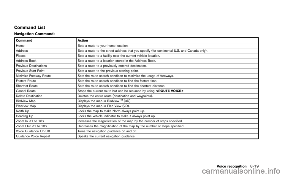
Command List
Navigation Command:
CommandAction
Home Sets a route to your home location.
Address Sets a route to the street address that you specify (for continental U.S. and Canada only) .
Places Sets a route to a facility near the current vehicle location.
Address Book Sets a route to a location stored in the Address Book.
Previous Destinations Sets a route to a previously entered destination.
Previous Start Point Sets a route to the previous starting point.
Minimize Freeway Route Sets the route search condition to minimize the usage of freeways.
Fastest Route Sets the route search condition to find the fastest time.
Shortest Route Sets the route search condition to find the shortest distance.
Cancel Route Stops the current route but can be resumed by using
Delete Destination Deletes the entire route (destination and waypoints) .
Birdview Map Displays the map in Birdview
TM(3D) .
Planview Map Displays the map in Plan View (2D) .
North Up Locks the map to make North always point up.
Heading Up Locks the vehicle indicator to make it always point up.
Zoom In <1 to 13> Increases the magnification of the map by the number of steps specified.
Zoom Out <1 to 13> Decreases the magnification of the map by the number of steps specified.
Voice Guidance On/Off Turns the navigation guidance on and off.
Guidance Voice Repeat Speaks the current navigation guidance.
Voice recognition8-19
Page 243 of 298
10-8Multi function meter
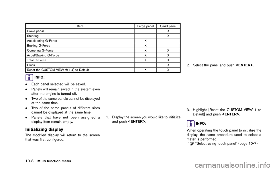
ItemLarge panel Small panel
Brake pedal X
Steering X
Accelerating G-Force X
Braking G-Force X
Cornering G-Force XX
Accel/Braking G-Force XX
Total G-Force XX
Clock X
Reset the CUSTOM VIEW #(1-4) to Default XX
INFO:
. Each panel selected will be saved.
. Panels will remain saved in the system even
after the engine is turned off.
. Two of the same panels cannot be displayed
at the same time.
. Two of the same panels of different sizes
cannot be displayed at the same time.
. Panels that have not been assigned a
display item remain empty.
Initializing display
The modified display will return to the screen
that was first configured.
1. Display the screen you would like to initialize
and push
2. Select the panel and push
3. Highlight [Reset the CUSTOM VIEW 1 to
Default] and push
INFO:
When operating the touch panel to initialize the
display, the same procedure used to select a
meter is performed.
“Select using touch panel” (page 10-7)
Page 251 of 298
10-16Multi function meter
INFO:
. Due to the slope of a road, this meter may
register G-Force even when the vehicle is
stopped. This is not a malfunction.
. When the VDC or the ABS is activated, a
mark will appear on the far left side of the
panel (large panel only) .
. The scale of the readout is adjusted auto-
matically to accommodate readings that
exceed the upper limit of the meter.
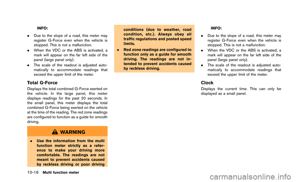
Total G-Force
Displays the total combined G-Force exerted on
the vehicle. In the large panel, this meter
displays readings for the past 20 seconds. In
the small panel, this meter displays the total
combined G-Force being exerted on the vehicle
at the time of the reading. The red zone readings
are configured to function as a guide for smooth
driving.
WARNING
.Use the information from the multi
function meter strictly as a refer-
ence to make your driving more
comfortable. The readings are not
meant to prevent accidents caused
by reckless driving or poor driving conditions (due to weather, road
condition, etc.) . Always obey all
traffic regulations and posted speed
limits.
. Red zone readings are configured to
function only as a guide for smooth
driving. The readings are not in-
tended to prevent accidents caused
by reckless driving.
INFO:
. Due to the slope of a road, this meter may
register G-Force even when the vehicle is
stopped. This is not a malfunction.
. When the VDC or the ABS is activated, a
mark will appear on the far left side of the
panel (large panel only) .
. The scale of the readout is adjusted auto-
matically to accommodate readings that
exceed the upper limit of the meter.
Clock
Displays the current time. This can only be
displayed as a small panel.
Page 252 of 298
INFO:
. The displayed clock time is set by the GPS
system.
. The clock time may not be displayed on the
screen when the system is not receiving a
GPS signal, even when the system is set to
display the time.
. You can choose to display the clock in the
12-hour/24-hour format.
“Clock settings” (page 7-7)
ACCELERATION SCREEN
The acceleration screen displays the results of
how the vehicle behaves based on the manner in
which you operate the vehicle. The information
displayed is for confirmation purposes. The
results of how you use the accelerator pedal
can be displayed as an acceleration g-force
timeline. You can use this information to improve
your operation of the accelerator pedal.
WARNING
.Use the information from the multi
function meter strictly as a refer-
ence to make your driving more
comfortable. The readings are not
meant to prevent accidents caused
by reckless driving or poor driving
conditions (due to weather, road
condition, etc.) . Always obey all
traffic regulations and posted speed
limits.
. Red zone readings are configured to
function only as a guide for smooth
driving. The readings are not in-
tended to prevent accidents caused
by reckless driving.
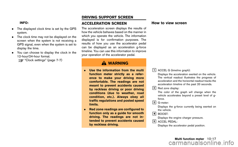
How to view screen
&1ACCEL G (timeline graph):
Displays the acceleration exerted on the vehicle.
The vertical readout illustrates the progress of
acceleration and the horizontal readout tracks the
acceleration timeline of the past 20 seconds.
&2Red zone display:
The color of the graph will change when the
vehicle accelerates beyond a preset level of g-
force.
&3G-meter:
Displays the g-force currently being exerted on
the vehicle.
&41BOOST:
Displays the engine charger pressure.
&5ACCEL PEDAL:
Displays the accelerator pedal position.
Multi function meter10-17
DRIVING SUPPORT SCREEN
Page 258 of 298
2. Each time you push
time will be recorded into the system and
will be viewable in the list.
3. Push
function will stop timing.
INFO:
. The STOP WATCH function can only be
used when the clock is activated.
. If using the driver’s notes, the STOP
WATCH function is unavailable. To use the
STOP WATCH function, first finish using the
driver’s notes.
. If the ignition is in the OFF position, you will
not be able to use the STOP WATCH
function.
. If the ignition is put into the ACC or the OFF
position while using the timer, timing will
end.
. The timer will continue timing while you
display other screens until you push
. The maximum time that the system timer can
display is a recorded time of up to 9 hours
59 minutes and 59.99 seconds.
. When timing has finished, the upper timer
will reset to 00:00.0
. When the recorded time and the finished
recording time are displayed, they tempora-
rily interrupt the time recorder display and
are displayed in large numbers. The re-
corded time will disappear automatically
after 5-10 seconds. .
When screens other than the multi function
meter are displayed, the STOP WATCH
screen will not interrupt the display.
Checking timed distance list
You can review the list of past measured times.
1. Select [TIME LOG]. The list screen will be
displayed.
2. Select the record you would like to display.
The menu screen will be displayed.
Multi function meter10-23
Page 268 of 298
— If one section between waypoints cannotbe calculated, none of the route will be
displayed.
— The route may not connect completely at some waypoints.
— The route may require a U-turn close to some waypoints.
. Route calculation may not be completed in
the following cases.
— If there is no main road within a range of
1.5 miles (2.5 km) from the vehicle, a
message saying so will appear on the
screen. Try recalculating when the vehi-
cle is closer to a main road.
— If there is no main road within a range of 1.5 miles (2.5 km) from the destination or
waypoint, a message saying so will
appear on the screen. Try setting the
location closer to a main road.
— If the vehicle is too close to the destina- tion or if there are no roads to the
destination, a message saying so will
appear on the screen.
— If it is impossible to reach the destination or waypoints because of traffic regula-
tions, etc. — If the only route to reach the destination
or waypoints is extremely complicated.
— If the destination, current vehicle position or waypoint is within the “Avoid Area”.
— If a part of the route is included in the “Avoid Area”.
. The following may occur when the route is
displayed.
— If you calculate a route on a main road,
the starting point of the route may not
exactly match the current vehicle loca-
tion.
— The endpoint of the route may not exactly match the destination.
— If you calculate a route on a main road, the system may display a route from
another main road. This may be because
the position of the vehicle icon is not
accurate. In this case, park the vehicle in
a safe location and reset the vehicle icon,
or continue driving to see if the position
of the vehicle icon is automatically
adjusted before recalculating the route.
— There are cases in which the system shows an indirect route to reach the
destination or waypoints, if you set them
from stored or facility information. In
order to correct this, you must be careful
about the traffic direction, especially when lanes with different travel directions
are shown separately, such as inter-
changes and service areas.
— This system makes no distinction be- tween limited traffic control and total
control (blockage) . It may show an
indirect route even if the road is usable.
— Even if the freeway preference is set to OFF, a route that uses the freeway may
be suggested.
— Even if the ferry preference is set to OFF, a route that uses a ferry line may be
suggested.
— Ferry lines, excluding those that are only for pedestrians, bicycles and motor-
cycles, are stored in this system. Take
into consideration the travel time required
and operational condition before decid-
ing whether to use them or not.
General system information11-7
Page 294 of 298
13 Index
A
About map data........................................................ 11-13
About map icons...................................................... 11-13
About multi function meter ....................................... 10-2
About route guidance ................................................ 2-48
Acceleration screen................................................. 10-17
Address book................................................................. 2-3
Air flow control............................................................... 5-5
Air recirculation.............................................................. 5-5
Alternate Command Mode........................................ 8-13
Antenna.......................................................................... 3-11
Audio operation precautions...................................... 3-2
Audio settings................................................................ 7-3
Audio system.................................................... 3-2, 12-10
Automatic air intake control........................................ 5-5
Automatic operation ..................................................... 5-3
Automatic reroute.......................................................... 2-4
Automatically display warnings/watches............... 6-20
Avoid area....................................................................... 2-3
B
Basics of voice guidance.......................................... 11-8
Before starting .................................................... 8-4, 8-17
Birdview
TM....................................................................... 2-4
BirdviewTM(3D) map ................................................... 2-6
Bluetooth®Hands-Free Phone System .... 4-2, 12-11
Bluetooth®streaming audio ..................................... 3-20
Braking screen.......................................................... 10-19
Building graphics .......................................................... 2-6
C
Camera settings ............................................................ 9-7
Car phone or CB radio ............................................. 3-26 CD/DVD/USB device care and cleaning.............. 3-25
Changing map view.................................................... 2-11
Changing scale of map ............................................... 2-9
Character (letters and numbers) input screen .... 1-14
Characteristics of liquid crystal display.............. 11-16
Clock settings................................................................ 7-7
Comfort settings............................................................ 7-8
Confirming how to use voice commands .... 8-2, 8-14
Connecting procedure................................................. 4-4
Control buttons.............................................................. 4-4
Control buttons and functions................................... 1-4
Control panel.................................................................. 1-4
Cooling and/or dehumidified heating (AUTO)....... 5-3
Current vehicle location............................................. 11-2
Custom view screen................................................... 10-6
Customer assistance.................................................. 12-2
D
Dehumidified defrosting or defogging..................... 5-4
Delete destination ....................................................... 2-43
Delete stored items .................................................... 2-96
Deleting stored item................................................... 2-86
Destination screen...................................................... 2-23
Destination weather on suggested
route screen ................................................................. 6-19
Detailed Map Coverage Areas (MCA) for
navigation system........................................................ 11-5
Detour .............................................................................. 2-4
Digital media slots ........................................................ 1-7
Directions provided and distances to
guide points.................................................................. 11-8
Display adjustment........................................................ 7-4
Display of current vehicle location.......................... 11-2
Display settings ............................................................. 7-4
Display urgent traffic information .............................. 6-9
Displaying current vehicle location........................... 2-7
Displaying how to operate Voice
Recognition System ................................................... 8-13
Displaying weather information screen.................. 6-13
Driving record screen.............................................. 10-22
Driving support screen ........................................... 10-17
During a call ................................................................... 4-7
DVD (Digital Versatile Disc) player operation...... 3-15
E
Editing address book................................................. 2-77
End-user terms ......................................................... 11-14
Example of touch panel operation.......................... 1-13
F
Fan speed control......................................................... 5-5
Features of multi function display system............... 1-2
Features of this navigation system ........................... 2-3
Finding address........................................................... 2-25
Finding place................................................................ 2-27
FM-AM-SAT radio with Compact Disc
(CD) player ................................................................... 3-11
For safe operation......................................................... 0-2
Fuel economy information........................................... 6-4
Full screen display ...................................................... 7-11
Functions disabled while driving............................... 0-4
G
Giving voice commands................................... 8-4, 8-17