stop start NISSAN LATIO 2008 Service User Guide
[x] Cancel search | Manufacturer: NISSAN, Model Year: 2008, Model line: LATIO, Model: NISSAN LATIO 2008Pages: 2771, PDF Size: 60.61 MB
Page 136 of 2771

AT-124
< SERVICE INFORMATION >
DTC P0744 A/T TCC S/V FUNCTION (LOCK-UP)
DTC P0744 A/T TCC S/V FUNCTION (LOCK-UP)
DescriptionINFOID:0000000001703260
• This malfunction will not be detected while the OD OFF indicator lamp is indicating another self-diagnosis
malfunction.
• This malfunction is detected when the A/T does not shift into fourth gear position or the torque converter
clutch does not lock-up as instructed by the TCM. This is not caused by electrical malfunction (circuits open
or shorted) but by mechanical malfunction such as control valve sticking, improper solenoid valve operation,
malfunctioning oil pump or torque converter clutch, etc.
CONSULT-III Reference Value in Data Monitor ModeINFOID:0000000001703261
Remarks: Specification data are reference values.
On Board Diagnosis LogicINFOID:0000000001703262
• This is an OBD-II self-diagnostic item.
• Diagnostic trouble code “P0744 A/T TCC S/V FNCTN” with CONSULT-III is detected when A/T cannot per-
form lock-up even if electrical circuit is good.
• This diagnosis monitors actual gear position by checking the torque converter slip ratio calculated by TCM
as follows:
Torque converter slip ratio = A x C/B
A: Output shaft revolution signal from revolution sensor
B: Engine speed signal from ECM
C: Gear ratio determined as gear position which TCM supposes
If the actual gear position is much lower than the position (4th) supposed by TCM, the slip ratio will be much
less than normal. In case the ratio does not reach the specified value, TCM judges this diagnosis malfunc-
tion.
This malfunction will be caused when shift solenoid valve B is stuck closed.
• Gear positions supposed by TCM are as follows.
In case of gear position with no malfunctions: 1, 2, 3 and 4 positions
In case of gear position with shift solenoid valve B stuck closed: 1, 2, 2 and 1* positions to each gear position
above
*: “P0744 A/T TCC S/V FNCTN” is detected.
Possible CauseINFOID:0000000001703263
• Line pressure solenoid valve
• Torque converter clutch solenoid valve
• Each clutch
• Hydraulic control circuit
DTC Confirmation ProcedureINFOID:0000000001703264
CAUTION:
• Always drive vehicle at a safe speed.
• If performing this “DTC Confirmation Procedure” again, always turn ignition switch OFF and wait at
least 10 seconds before continuing.
After the repair, perform the following procedure to confirm the malfunction is eliminated.
WITH CONSULT-III
1. Start engine and select “DATA MONITOR” mode for “A/T” with CONSULT-III.
2. Touch “START”.
3. Make sure that output voltage of A/T fluid temperature sensor is within the range below.
FLUID TEMP SE: 0.4 - 1.5 V
If out of range, drive vehicle to decrease voltage (warm up the fluid) or stop engine to increase voltage
(cool down the fluid).
4. Select “TCC S/V FNCTN P0744” of “DTC WORK SUPPORT” mode for “A/T” with CONSULT-III and touch
“START”.
Item name Condition Display value (Approx)
TCC S/V DUTY Lock-up OFF ⇔ Lock-up ON 4% ⇔ 94%
Page 219 of 2771

SHIFT CONTROL SYSTEM
AT-207
< SERVICE INFORMATION >
D
E
F
G
H
I
J
K
L
MA
B
AT
N
O
P
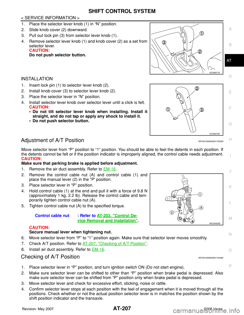
1. Place the selector lever knob (1) in “N” position.
2. Slide knob cover (2) downward.
3. Pull out lock pin (3) from selector lever knob (1).
4. Remove selector lever knob (1) and knob cover (2) as a set from
selector lever.
CAUTION:
Do not push selector button.
INSTALLATION
1. Insert lock pin (1) to selector lever knob (2).
2. Install knob cover (3) to selector lever knob (2).
3. Place the selector lever in “N” position.
4. Install selector lever knob over selector lever until a click is felt.
CAUTION:
• Do not tilt selector lever knob when installing. Install it
straight, and do not tap or apply any shock to install it.
• Do not push selector button.
Adjustment of A/T PositionINFOID:0000000001703359
Move selector lever from “P” position to “1” position. You should be able to feel the detents in each position. If
the detents cannot be felt or if the position indicator is improperly aligned, the control cable needs adjustment.
CAUTION:
Make sure that parking brake is applied before adjustment.
1. Remove the air duct assembly. Refer to EM-16
.
2. Remove the control cable nut (A) and control cable (1) and
place the manual lever (2) in the "P' position.
3. Place selector lever in “P” position.
4. Hold control cable (1) at the end and pull it with a force of 9.8 N
(approximately 1 kg, 2.2 lb). Release the control cable and tem-
porarily tighten control cable nut (A).
5. Tighten control cable nut (A) to the specified torque.
CAUTION:
Secure manual lever when tightening nut.
6. Move selector lever from “P” to “1” position again. Make sure that selector lever moves smoothly.
7. Check A/T position. Refer to AT-207, "
Checking of A/T Position".
8. Install air duct assembly. Refer to EM-16
.
Checking of A/T PositionINFOID:0000000001703360
1. Place selector lever in “P” position, and turn ignition switch ON (Do not start engine).
2. Make sure selector lever can be shifted to other than “P” position when brake pedal is depressed. Also
make sure selector lever can be shifted from “P” position only when brake pedal is depressed.
3. Move selector lever and check for excessive effort, sticking, noise or rattle.
4. Confirm selector lever stops at each position with the feel of engagement when it is moved through all the
positions. Check whether or not the actual position selector lever is in matches the position shown by the
shift position indicator and the transaxle.
SCIA6971E
SCIA6972E
Control cable nut : Refer to AT-203, "Control De-
vice Removal and Installation".WCIA0635E
Page 223 of 2771

A/T SHIFT LOCK SYSTEM
AT-211
< SERVICE INFORMATION >
D
E
F
G
H
I
J
K
L
MA
B
AT
N
O
P
•Selector lever can be moved from “P” position with ignition key in ON position and brake pedal
released.
•Selector lever can be moved from “P” position when ignition switch is removed from key cylinder.
SYMPTOM 2:
•Ignition key cannot be removed when selector lever is set to “P” position.
•Ignition key can be removed when selector lever is set to any position except “P” position.
1.CHECK KEY INTERLOCK CABLE
Check key interlock cable for damage.
OK or NG
OK >> GO TO 2.
NG >> Repair key interlock cable. Refer to AT-213, "
Removal and Installation" .
2.CHECK A/T POSITION
Check A/T position. Refer to AT-207, "
Checking of A/T Position" .
OK or NG
OK >> GO TO 3.
NG >> Adjust control cable. Refer to AT-207, "
Adjustment of A/T Position" .
3.CHECK SHIFT LOCK SOLENOID AND PARK POSITION SWITCH
1. Turn ignition switch ON. (Do not start engine.)
2. Selector lever is set in “P” position.
3. Check operation sound.
OK or NG
OK >>INSPECTION END
NG >> GO TO 4.
4.CHECK POWER SOURCE
1. Turn ignition switch ON. (Do not start engine.)
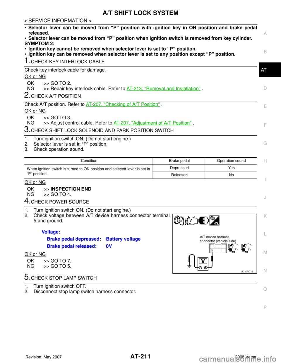
2. Check voltage between A/T device harness connector terminal
5 and ground.
OK or NG
OK >> GO TO 7.
NG >> GO TO 5.
5.CHECK STOP LAMP SWITCH
1. Turn ignition switch OFF.
2. Disconnect stop lamp switch harness connector.
Condition Brake pedal Operation sound
When ignition switch is turned to ON position and selector lever is set in
“P” position.Depressed Yes
Released No
Voltage:
Brake pedal depressed: Battery voltage
Brake pedal released: 0V
SCIA7171E
Page 443 of 2771

SQUEAK AND RATTLE TROUBLE DIAGNOSES
BL-9
< SERVICE INFORMATION >
C
D
E
F
G
H
J
K
L
MA
B
BL
N
O
P
SILICONE GREASE
Used instead of UHMW tape that will be visible or not fit.
Note: Will only last a few months.
SILICONE SPRAY
Use when grease cannot be applied.
DUCT TAPE
Use to eliminate movement.
CONFIRM THE REPAIR
Confirm that the cause of a noise is repaired by test driving the vehicle. Operate the vehicle under the same
conditions as when the noise originally occurred. Refer to the notes on the Diagnostic Worksheet.
Generic Squeak and Rattle TroubleshootingINFOID:0000000001703945
Refer to Table of Contents for specific component removal and installation information.
INSTRUMENT PANEL
Most incidents are caused by contact and movement between:
1. The cluster lid A and instrument panel
2. Acrylic lens and combination meter housing
3. Instrument panel to front pillar garnish
4. Instrument panel to windshield
5. Instrument panel mounting pins
6. Wiring harnesses behind the combination meter
7. A/C defroster duct and duct joint
These incidents can usually be located by tapping or moving the components to duplicate the noise or by
pressing on the components while driving to stop the noise. Most of these incidents can be repaired by apply-
ing felt cloth tape or silicone spray (in hard to reach areas). Urethane pads can be used to insulate wiring har-
ness.
CAUTION:
Do not use silicone spray to isolate a squeak or rattle. If you saturate the area with silicone, you will
not be able to recheck the repair.
CENTER CONSOLE
Components to pay attention to include:
1. Shifter assembly cover to finisher
2. A/C control unit and cluster lid C
3. Wiring harnesses behind audio and A/C control unit
The instrument panel repair and isolation procedures also apply to the center console.
DOORS
Pay attention to the:
1. Finisher and inner panel making a slapping noise
2. Inside handle escutcheon to door finisher
3. Wiring harnesses tapping
4. Door striker out of alignment causing a popping noise on starts and stops
Tapping or moving the components or pressing on them while driving to duplicate the conditions can isolate
many of these incidents. You can usually insulate the areas with felt cloth tape or insulator foam blocks from
the NISSAN Squeak and Rattle Kit (J-43980) to repair the noise.
TRUNK
Trunk noises are often caused by a loose jack or loose items put into the trunk by the owner.
In addition look for:
1. Trunk lid bumpers out of adjustment
2. Trunk lid striker out of adjustment
3. The trunk lid torsion bars knocking together
4. A loose license plate or bracket
Page 539 of 2771

INTELLIGENT KEY SYSTEM
BL-105
< SERVICE INFORMATION >
C
D
E
F
G
H
J
K
L
MA
B
BL
N
O
P
• If the following “symptoms” are detected, check systems shown in the ”Diagnoses/service procedure” col-
umn in this order.
ALL FUNCTIONS OF INTELLIGENT KEY SYSTEM DO NOT OPERATE
NOTE:
• Before performing the diagnosis in the following table, check “Trouble Diagnosis Procedure”. Refer to BL-99,
"Trouble Diagnosis Procedure".
• Make sure that vehicle is under the condition shown in “Conditions of vehicle” before starting diagnosis, and
check each symptom.
• If the following “symptoms” are detected, check systems shown in the “Diagnosis/service procedure” column
in this order.
Conditions of Vehicle (Operating Conditions)
• “ENGINE START BY I-KEY” and “LOCK/UNLOCK BY I-KEY” are ON when setting on CONSULT-III.
• Mechanical key is out of ignition switch.
• Ignition switch is not depressed.
• All doors are closed.
• Intelligent key is registered.
DOOR LOCK/UNLOCK FUNCTION MALFUNCTION
NOTE:
• Before performing the diagnosis in the following table, check “Trouble Diagnosis Procedure”. Refer to BL-99,
"Trouble Diagnosis Procedure".
• Make sure that vehicle is under the condition shown in “Conditions of vehicle” before starting diagnosis, and
check each symptom.
• If the following “symptoms” are detected, check systems shown in the “Diagnosis/procedure” column in this
order.
Conditions of Vehicle (Operating Conditions)
• “LOCK/UNLOCK BY I-KEY” is ON when setting on CONSULT-III.
• Mechanical key is out of ignition switch.
• Ignition switch is not depressed.
• All doors are closed.
• Intelligent Key is registered.
Symptom Diagnosis/service procedure Reference page
Engine start condition check1. Check CVT device (park position switch).
(With CVT)BL-136
2. Check key interlock solenoid (with M/T).BL-133
3. Check stop lamp switch (With CVT).BL-134
4. Check stop lamp switch (with M/T).BL-135
Symptom Diagnosis/service procedure Reference page
All function of Intelligent Key system dose not
operate.1. Check Intelligent Key unit power supply and ground
circuit.BL-110
2. Check Intelligent Key battery inspection.BL-142
3. Replace Intelligent Key unit.BL-142
Symptom Diagnosis/service procedure Reference page
Door lock/unlock does not operate by all request
switches.1. Check door switch (hatchback).BL-114
2. Check door switch (sedan).BL-117
3. Check key switch.BL-110
4. Check ignition knob switch.BL-113
5. Replace Intelligent Key unit.BL-142
Page 737 of 2771

BR-6
< SERVICE INFORMATION >
BRAKE PEDAL
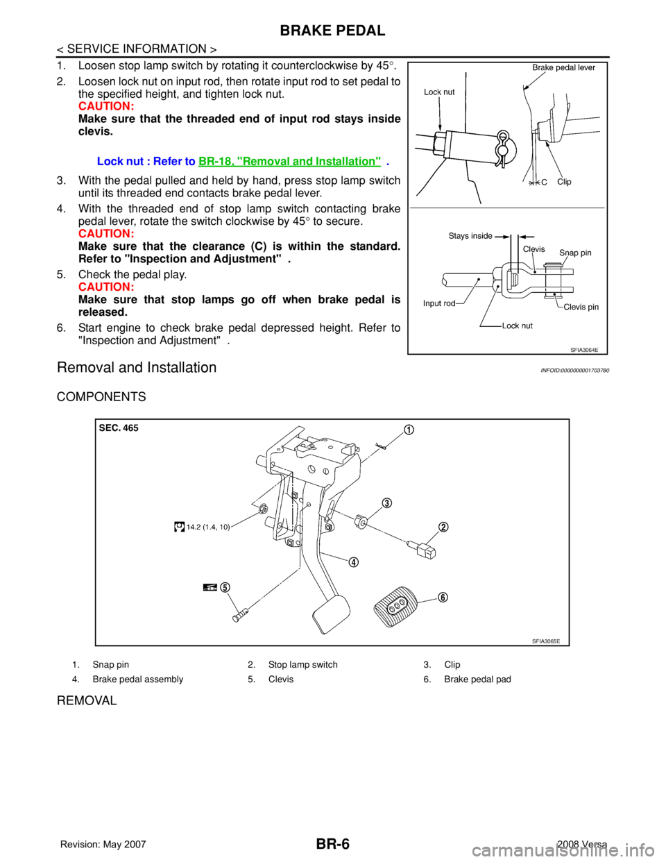
1. Loosen stop lamp switch by rotating it counterclockwise by 45°.
2. Loosen lock nut on input rod, then rotate input rod to set pedal to
the specified height, and tighten lock nut.
CAUTION:
Make sure that the threaded end of input rod stays inside
clevis.
3. With the pedal pulled and held by hand, press stop lamp switch
until its threaded end contacts brake pedal lever.
4. With the threaded end of stop lamp switch contacting brake
pedal lever, rotate the switch clockwise by 45° to secure.
CAUTION:
Make sure that the clearance (C) is within the standard.
Refer to "Inspection and Adjustment" .
5. Check the pedal play.
CAUTION:
Make sure that stop lamps go off when brake pedal is
released.
6. Start engine to check brake pedal depressed height. Refer to
"Inspection and Adjustment" .
Removal and InstallationINFOID:0000000001703780
COMPONENTS
REMOVAL
Lock nut : Refer to BR-18, "Removal and Installation" .
SFIA3064E
1. Snap pin 2. Stop lamp switch 3. Clip
4. Brake pedal assembly 5. Clevis 6. Brake pedal pad
SFIA3065E
Page 749 of 2771

BR-18
< SERVICE INFORMATION >
BRAKE BOOSTER
BRAKE BOOSTER
On Board InspectionINFOID:0000000001703791
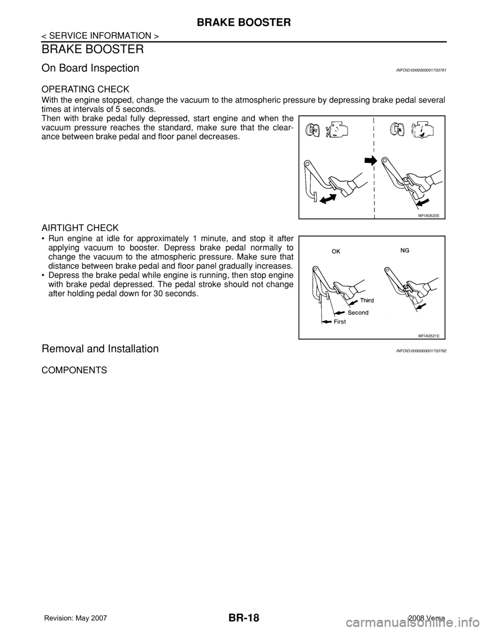
OPERATING CHECK
With the engine stopped, change the vacuum to the atmospheric pressure by depressing brake pedal several
times at intervals of 5 seconds.
Then with brake pedal fully depressed, start engine and when the
vacuum pressure reaches the standard, make sure that the clear-
ance between brake pedal and floor panel decreases.
AIRTIGHT CHECK
• Run engine at idle for approximately 1 minute, and stop it after
applying vacuum to booster. Depress brake pedal normally to
change the vacuum to the atmospheric pressure. Make sure that
distance between brake pedal and floor panel gradually increases.
• Depress the brake pedal while engine is running, then stop engine
with brake pedal depressed. The pedal stroke should not change
after holding pedal down for 30 seconds.
Removal and InstallationINFOID:0000000001703792
COMPONENTS
WFIA0520E
WFIA0521E
Page 767 of 2771
![NISSAN LATIO 2008 Service User Guide BRC-2
< SERVICE INFORMATION >[ABS]
PRECAUTIONS
SERVICE INFORMATION
PRECAUTIONS
Precaution for Supplemental Restraint System (SRS) "AIR BAG" and "SEAT BELT
PRE-TENSIONER"
INFOID:000000 NISSAN LATIO 2008 Service User Guide BRC-2
< SERVICE INFORMATION >[ABS]
PRECAUTIONS
SERVICE INFORMATION
PRECAUTIONS
Precaution for Supplemental Restraint System (SRS) "AIR BAG" and "SEAT BELT
PRE-TENSIONER"
INFOID:000000](/img/5/57360/w960_57360-766.png)
BRC-2
< SERVICE INFORMATION >[ABS]
PRECAUTIONS
SERVICE INFORMATION
PRECAUTIONS
Precaution for Supplemental Restraint System (SRS) "AIR BAG" and "SEAT BELT
PRE-TENSIONER"
INFOID:0000000001703818
The Supplemental Restraint System such as “AIR BAG” and “SEAT BELT PRE-TENSIONER”, used along
with a front seat belt, helps to reduce the risk or severity of injury to the driver and front passenger for certain
types of collision. This system includes seat belt switch inputs and dual stage front air bag modules. The SRS
system uses the seat belt switches to determine the front air bag deployment, and may only deploy one front
air bag, depending on the severity of a collision and whether the front occupants are belted or unbelted.
Information necessary to service the system safely is included in the SRS and SB section of this Service Man-
ual.
WARNING:
• To avoid rendering the SRS inoperative, which could increase the risk of personal injury or death in
the event of a collision which would result in air bag inflation, all maintenance must be performed by
an authorized NISSAN/INFINITI dealer.
• Improper maintenance, including incorrect removal and installation of the SRS, can lead to personal
injury caused by unintentional activation of the system. For removal of Spiral Cable and Air Bag
Module, see the SRS section.
• Do not use electrical test equipment on any circuit related to the SRS unless instructed to in this
Service Manual. SRS wiring harnesses can be identified by yellow and/or orange harnesses or har-
ness connectors.
Precaution for Brake SystemINFOID:0000000001703819
CAUTION:
• Refer to MA-10
for recommended brake fluid.
• Never reuse drained brake fluid.
• Be careful not to splash brake fluid on painted areas; it may cause paint damage. If brake fluid is
splashed on painted areas, wash it away with water immediately.
• To clean or wash all parts of master cylinder and disc brake caliper, use clean brake fluid.
• Never use mineral oils such as gasoline or kerosene. They will ruin rubber parts of the hydraulic sys-
tem.
• Use flare nut wrench when removing and installing brake
tube.
• If a brake fluid leak is found, the part must be disassembled
without fail. Then it has to be replaced with a new one if a
defect exists.
• Turn the ignition switch OFF and remove the connector of the
ABS actuator and electric unit (control unit) or the battery ter-
minal before performing the work.
• Always torque brake lines when installing.
• Burnish the brake contact surfaces after refinishing or replac-
ing rotors, after replacing pads, or if a soft pedal occurs at
very low mileage. Refer to BR-28, "
Brake Burnishing Proce-
dure".
WARNING:
• Clean brake pads and shoes with a waste cloth, then wipe with a dust collector.
Precaution for Brake ControlINFOID:0000000001703821
• During ABS operation, the brake pedal may vibrate lightly and a mechanical noise may be heard. This is
normal.
• Just after starting the vehicle, the brake pedal may vibrate or motor operating noises may be heard from
engine compartment. This is normal due to the self check operation.
• Stopping distance may be longer than that of vehicles without ABS when vehicle drives on rough, gravel, or
snow-covered (fresh, deep snow) roads.
SBR686C
Page 768 of 2771
![NISSAN LATIO 2008 Service User Guide PRECAUTIONS
BRC-3
< SERVICE INFORMATION >[ABS]
C
D
E
G
H
I
J
K
L
MA
B
BRC
N
O
P
• When an error is indicated by ABS or another warning lamp, collect all necessary information from customer
(what sym NISSAN LATIO 2008 Service User Guide PRECAUTIONS
BRC-3
< SERVICE INFORMATION >[ABS]
C
D
E
G
H
I
J
K
L
MA
B
BRC
N
O
P
• When an error is indicated by ABS or another warning lamp, collect all necessary information from customer
(what sym](/img/5/57360/w960_57360-767.png)
PRECAUTIONS
BRC-3
< SERVICE INFORMATION >[ABS]
C
D
E
G
H
I
J
K
L
MA
B
BRC
N
O
P
• When an error is indicated by ABS or another warning lamp, collect all necessary information from customer
(what symptoms are present under what conditions) and check for simple causes before starting diagnosis.
Besides electrical system inspection, check brake booster operation, brake fluid level, and fluid leaks.
• If incorrect tire sizes or types are installed on the vehicle or brake pads are not Genuine NISSAN parts, stop-
ping distance or steering stability may deteriorate.
• If there is a radio, antenna or related wiring near the control module, ABS function may have a malfunction
or error.
• If aftermarket parts (car stereo, CD player, etc.) have been installed, check for incidents such as harness
pinches, open circuits or improper wiring.
Precaution for CAN SystemINFOID:0000000001703822
• Do not apply voltage of 7.0V or higher to terminal to be measured.
• Maximum open terminal voltage of tester in use must be less than 7.0V.
• Before checking harnesses, turn ignition switch OFF and disconnect battery negative cable.
• Area to be repaired must be soldered and wrapped with tape.
Make sure that fraying of twisted wire is within 110 mm (4.33 in).
• Do not make a bypass connection to repaired area. (If the circuit is
bypassed, characteristics of twisted wire will be lost.)
PKIA0306E
PKIA0307E
Page 770 of 2771
![NISSAN LATIO 2008 Service User Guide SYSTEM DESCRIPTION
BRC-5
< SERVICE INFORMATION >[ABS]
C
D
E
G
H
I
J
K
L
MA
B
BRC
N
O
P
SYSTEM DESCRIPTION
System ComponentINFOID:0000000001703825
ABS FunctionINFOID:0000000001703826
• The Anti-Lock NISSAN LATIO 2008 Service User Guide SYSTEM DESCRIPTION
BRC-5
< SERVICE INFORMATION >[ABS]
C
D
E
G
H
I
J
K
L
MA
B
BRC
N
O
P
SYSTEM DESCRIPTION
System ComponentINFOID:0000000001703825
ABS FunctionINFOID:0000000001703826
• The Anti-Lock](/img/5/57360/w960_57360-769.png)
SYSTEM DESCRIPTION
BRC-5
< SERVICE INFORMATION >[ABS]
C
D
E
G
H
I
J
K
L
MA
B
BRC
N
O
P
SYSTEM DESCRIPTION
System ComponentINFOID:0000000001703825
ABS FunctionINFOID:0000000001703826
• The Anti-Lock Brake System detects wheel revolution while braking and improves handling stability during
sudden braking by electrically preventing wheel lockup. Maneuverability is also improved for avoiding obsta-
cles during emergency braking.
• If the electrical system malfunctions, the Fail-Safe function is activated, the ABS becomes inoperative and
the ABS warning lamp turns on.
• The electrical system can be diagnosed using CONSULT-III.
• During ABS operation, the brake pedal may vibrate lightly and a mechanical noise may be heard. This is
normal.
• Just after starting the vehicle, the brake pedal may vibrate or motor operating noises may be heard from the
engine compartment. This is normal due to the self check operation.
• Stopping distance may be longer than that of vehicles without ABS when vehicle drives on rough, gravel, or
snow-covered (fresh, deep snow) roads.
EBD FunctionINFOID:0000000001703827
• Electronic Brake Distribution is a function that detects subtle slippages between the front and rear wheels
during braking, and it improves handling stability by electronically controlling the brake fluid pressure which
results in reduced rear wheel slippage.
• If the electrical system malfunctions, the Fail-Safe function is activated, the EBD and ABS become inopera-
tive, and the ABS warning lamp and brake warning lamp are turned on.
• The electrical system can be diagnosed using CONSULT-III.
• During EBD operation, the brake pedal may vibrate lightly and a mechanical noise may be heard. This is
normal.
• Just after starting the vehicle, the brake pedal may vibrate or motor operating noises may be heard from the
engine compartment. This is normal due to the self check operation.
Fail-Safe FunctionINFOID:0000000001703828
CAUTION:
If the Fail-Safe function is activated, perform the Self Diagnosis for ABS system.
ABS/EBD SYSTEM
In case of an electrical malfunction with the ABS, the ABS warning lamp will turn on. In case of an electrical
malfunction with the EBD system, the brake warning lamp and the ABS warning lamp will turn on.
The system will revert to one of the following conditions of the Fail-Safe function.
1. For ABS malfunction, only the EBD is operative and the condition of the vehicle is the same condition of
vehicles without ABS system.
WFIA0118E