lock NISSAN LATIO 2008 Service Owner's Guide
[x] Cancel search | Manufacturer: NISSAN, Model Year: 2008, Model line: LATIO, Model: NISSAN LATIO 2008Pages: 2771, PDF Size: 60.61 MB
Page 87 of 2771
TROUBLE DIAGNOSIS
AT-75
< SERVICE INFORMATION >
D
E
F
G
H
I
J
K
L
MA
B
AT
N
O
P
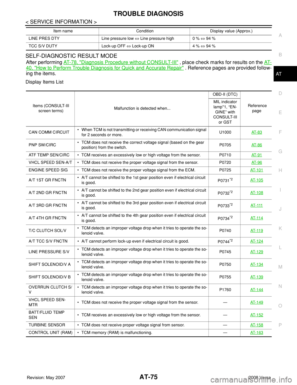
SELF-DIAGNOSTIC RESULT MODE
After performing AT-78, "Diagnosis Procedure without CONSULT-III" , place check marks for results on the AT-
40, "How to Perform Trouble Diagnosis for Quick and Accurate Repair" . Reference pages are provided follow-
ing the items.
Display Items List
LINE PRES DTY Line pressure low ⇔ Line pressure high 0 % ⇔ 94 %
TCC S/V DUTY Lock-up OFF ⇔ Lock-up ON 4 % ⇔ 94 % Item name Condition Display value (Approx.)
Items (CONSULT-III
screen terms)Malfunction is detected when...OBD-II (DTC)
Reference
page MIL indicator
lamp*1, “EN-
GINE” with
CONSULT-III
or GST
CAN COMM CIRCUIT• When TCM is not transmitting or receiving CAN communication signal
for 2 seconds or more.U1000AT- 8 3
PNP SW/CIRC• TCM does not receive the correct voltage signal (based on the gear
position) from the switch.P0705AT- 8 6
ATF TEMP SEN/CIRC • TCM receives an excessively low or high voltage from the sensor. P0710AT- 9 1
VHCL SPEED SEN-A/T • TCM does not receive the proper voltage signal from the sensor. P0720AT- 9 6
ENGINE SPEED SIG • TCM does not receive the proper voltage signal from the ECM. P0725AT- 1 0 1
A/T 1ST GR FNCTN• A/T cannot be shifted to the 1st gear position even if electrical circuit
is good.P0731*2AT- 1 0 5
A/T 2ND GR FNCTN• A/T cannot be shifted to the 2nd gear position even if electrical circuit
is good.P0732*2AT- 1 0 8
A/T 3RD GR FNCTN• A/T cannot be shifted to the 3rd gear position even if electrical circuit
is good.P0733*2AT- 111
A/T 4TH GR FNCTN• A/T cannot be shifted to the 4th gear position even if electrical circuit
is good.P0734*2AT- 11 4
T/C CLUTCH SOL/V• TCM detects an improper voltage drop when it tries to operate the so-
lenoid valve.P0740AT- 11 9
A/T TCC S/V FNCTN • A/T cannot perform lock-up even if electrical circuit is good.
P0744*2AT- 1 2 4
LINE PRESSURE S/V• TCM detects an improper voltage drop when it tries to operate the so-
lenoid valve.P0745AT- 1 2 9
SHIFT SOLENOID/V A• TCM detects an improper voltage drop when it tries to operate the so-
lenoid valve.P0750AT- 1 3 4
SHIFT SOLENOID/V B• TCM detects an improper voltage drop when it tries to operate the so-
lenoid valve.P0755 AT- 1 3 9
OVERRUN CLUTCH S/
V• TCM detects an improper voltage drop when it tries to operate the so-
lenoid valve.P1760AT- 1 4 4
VHCL SPEED SEN-
MTR• TCM does not receive the proper voltage signal from the sensor. —AT- 1 4 9
BATT/FLUID TEMP
SEN• TCM receives an excessively low or high voltage from the sensor. —AT- 1 5 2
TURBINE SENSOR • TCM does not receive proper voltage signal from sensor. —AT- 1 5 8
CONTROL UNIT (RAM) • TCM memory (RAM) is malfunctioning. —AT- 1 6 3
Page 90 of 2771
AT-78
< SERVICE INFORMATION >
TROUBLE DIAGNOSIS
Diagnosis Procedure without CONSULT-III
INFOID:0000000001703194
TCM SELF-DIAGNOSTIC PROCEDURE
Description
If a malfunction occurs in electrical system, turning ignition switch ON will illuminate OD OFF indicator lamp for
2 seconds. To detect a malfunction, entering a self-diagnosis start signal retrieves information on malfunctions
from memory and indicates malfunction by blinking OD OFF indicator lamp.
Diagnostic Procedure
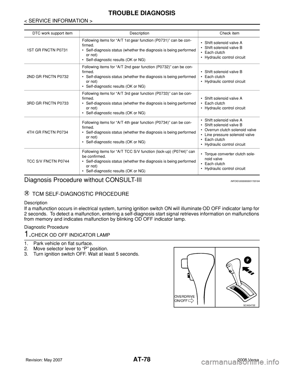
1.CHECK OD OFF INDICATOR LAMP
1. Park vehicle on flat surface.
2. Move selector lever to “P” position.
3. Turn ignition switch OFF. Wait at least 5 seconds.
DTC work support itemDescription Check item
1ST GR FNCTN P0731Following items for “A/T 1st gear function (P0731)” can be con-
firmed.
• Self-diagnosis status (whether the diagnosis is being performed
or not)
• Self-diagnostic results (OK or NG)• Shift solenoid valve A
• Shift solenoid valve B
• Each clutch
•Hydraulic control circuit
2ND GR FNCTN P0732Following items for “A/T 2nd gear function (P0732)” can be con-
firmed.
• Self-diagnosis status (whether the diagnosis is being performed
or not)
• Self-diagnostic results (OK or NG)• Shift solenoid valve B
• Each clutch
•Hydraulic control circuit
3RD GR FNCTN P0733Following items for “A/T 3rd gear function (P0733)” can be con-
firmed.
• Self-diagnosis status (whether the diagnosis is being performed
or not)
• Self-diagnostic results (OK or NG)• Shift solenoid valve A
• Each clutch
•Hydraulic control circuit
4TH GR FNCTN P0734Following items for “A/T 4th gear function (P0734)” can be con-
firmed.
• Self-diagnosis status (whether the diagnosis is being performed
or not)
• Self-diagnostic results (OK or NG)• Shift solenoid valve A
• Shift solenoid valve B
• Overrun clutch solenoid valve
• Line pressure solenoid valve
• Each clutch
•Hydraulic control circuit
TCC S/V FNCTN P0744Following items for “A/T TCC S/V function (lock-up) (P0744)” can
be confirmed.
• Self-diagnosis status (whether the diagnosis is being performed
or not)
• Self-diagnostic results (OK or NG)• Torque converter clutch sole-
noid valve
• Each clutch
•Hydraulic control circuit
SCIA5472E
Page 91 of 2771
TROUBLE DIAGNOSIS
AT-79
< SERVICE INFORMATION >
D
E
F
G
H
I
J
K
L
MA
B
AT
N
O
P
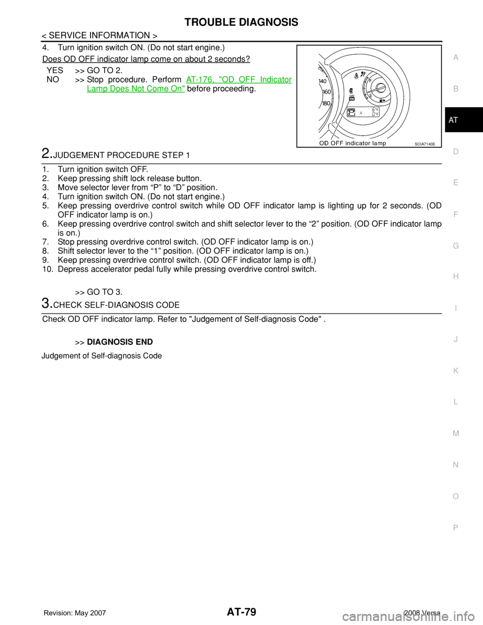
4. Turn ignition switch ON. (Do not start engine.)
Does OD OFF indicator lamp come on about 2 seconds?
YES >> GO TO 2.
NO >> Stop procedure. Perform AT-176, "
OD OFF Indicator
Lamp Does Not Come On" before proceeding.
2.JUDGEMENT PROCEDURE STEP 1
1. Turn ignition switch OFF.
2. Keep pressing shift lock release button.
3. Move selector lever from “P” to “D” position.
4. Turn ignition switch ON. (Do not start engine.)
5. Keep pressing overdrive control switch while OD OFF indicator lamp is lighting up for 2 seconds. (OD
OFF indicator lamp is on.)
6. Keep pressing overdrive control switch and shift selector lever to the “2” position. (OD OFF indicator lamp
is on.)
7. Stop pressing overdrive control switch. (OD OFF indicator lamp is on.)
8. Shift selector lever to the “1” position. (OD OFF indicator lamp is on.)
9. Keep pressing overdrive control switch. (OD OFF indicator lamp is off.)
10. Depress accelerator pedal fully while pressing overdrive control switch.
>> GO TO 3.
3.CHECK SELF-DIAGNOSIS CODE
Check OD OFF indicator lamp. Refer to "Judgement of Self-diagnosis Code" .
>>DIAGNOSIS END
Judgement of Self-diagnosis Code
SCIA7140E
Page 102 of 2771
AT-90
< SERVICE INFORMATION >
DTC P0705 PARK/NEUTRAL POSITION (PNP) SWITCH
Component Inspection
INFOID:0000000001703208
PNP SWITCH
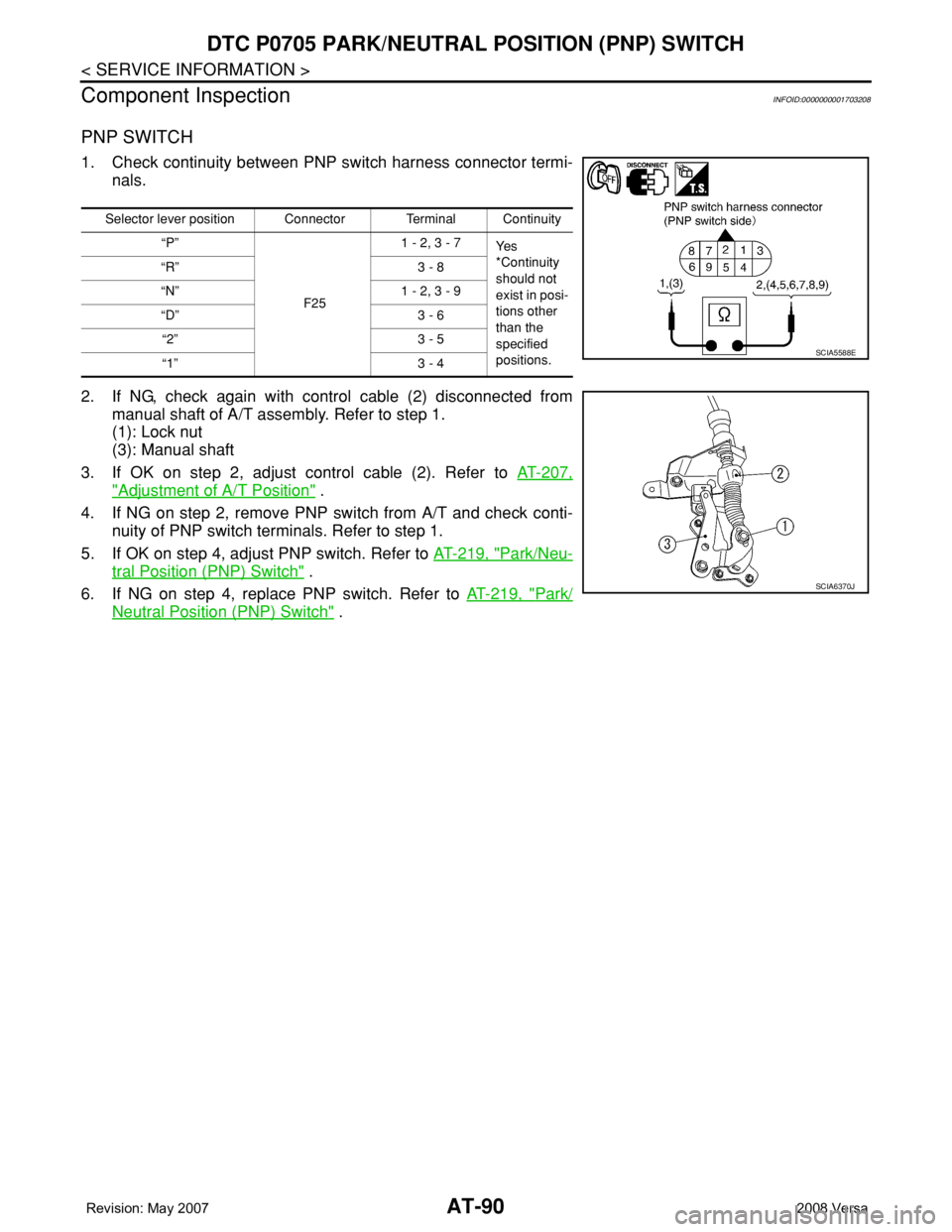
1. Check continuity between PNP switch harness connector termi-
nals.
2. If NG, check again with control cable (2) disconnected from
manual shaft of A/T assembly. Refer to step 1.
(1): Lock nut
(3): Manual shaft
3. If OK on step 2, adjust control cable (2). Refer to AT-207,
"Adjustment of A/T Position" .
4. If NG on step 2, remove PNP switch from A/T and check conti-
nuity of PNP switch terminals. Refer to step 1.
5. If OK on step 4, adjust PNP switch. Refer to AT-219, "
Park/Neu-
tral Position (PNP) Switch" .
6. If NG on step 4, replace PNP switch. Refer to AT-219, "
Park/
Neutral Position (PNP) Switch" .
Selector lever position Connector Terminal Continuity
“P”
F251 - 2, 3 - 7
Ye s
*Continuity
should not
exist in posi-
tions other
than the
specified
positions. “R” 3 - 8
“N” 1 - 2, 3 - 9
“D” 3 - 6
“2” 3 - 5
“1” 3 - 4
SCIA5588E
SCIA6370J
Page 108 of 2771

AT-96
< SERVICE INFORMATION >
DTC P0720 VEHICLE SPEED SENSOR A/T (REVOLUTION SENSOR)
DTC P0720 VEHICLE SPEED SENSOR A/T (REVOLUTION SENSOR)
DescriptionINFOID:0000000001703217
The revolution sensor detects the revolution of the idler gear parking pawl lock gear and emits a pulse signal.
The pulse signal is sent to the TCM which converts it into vehicle speed.
CONSULT-III Reference Value in Data Monitor ModeINFOID:0000000001703218
Remarks: Specification data are reference values.
On Board Diagnosis LogicINFOID:0000000001703219
• This is an OBD-II self-diagnostic item.
• Diagnostic trouble code “P0720 VHCL SPEED SEN-AT” with CONSULT-III or 1st judgement flicker without
CONSULT-III is detected when TCM does not receive the proper voltage signal from the sensor.
Possible CauseINFOID:0000000001703220
• Harness or connector
(The sensor circuit is open or shorted.)
• Revolution sensor
DTC Confirmation ProcedureINFOID:0000000001703221
CAUTION:
• Always drive vehicle at a safe speed.
• Be careful not to rev engine into the red zone on the tachometer.
• If performing this “DTC Confirmation Procedure” again, always turn ignition switch OFF and wait at
least 10 seconds before continuing.
After the repair, perform the following procedure to confirm the malfunction is eliminated.
WITH CONSULT-III
1. Turn ignition switch ON and select “DATA MONITOR” mode for “A/T” with CONSULT-III.
2. Touch “START”.
3. Drive vehicle and check for an increase of “VHCL/S SE-MTR” value.
If the check result is NG, go to AT-98, "
Diagnosis Procedure" .
If the check result is OK, go to following step.
4. Select “DATA MONITOR” mode for “A/T” with CONSULT-III.
5. Touch “START”.
6. Start engine and maintain the following conditions for at least 5 consecutive seconds.
VEHICLE SPEED: 30 km/h (19 MPH) or more
THROTTLE POSI: More than 1.0/8
SLCT LVR POSI: “D” position
Driving location: Driving the vehicle uphill (increased engine load) will help maintain the driving
conditions required for this test.
If the check result is NG, go to AT-98, "
Diagnosis Procedure" .
If the check result is OK, go to following step.
7. Maintain the following conditions for at least 5 consecutive seconds.
ENGINE SPEED: 3,500 rpm or more
THROTTLE POSI: More than 1.0/8
SLCT LVR POSI: “D” position
Driving location: Driving the vehicle uphill (increased engine load) will help maintain the driving
conditions required for this test.
WITH GST
Follow the procedure “WITH CONSULT-III”.
WITHOUT CONSULT-III
1. Start engine.
Item name Condition Display value
VHCL/S SE-A/T During driving Approximately matches the speedometer reading.
Page 126 of 2771

AT-114
< SERVICE INFORMATION >
DTC P0734 A/T 4TH GEAR FUNCTION
DTC P0734 A/T 4TH GEAR FUNCTION
DescriptionINFOID:0000000001703246
• This malfunction will not be detected while the OD OFF indicator lamp is indicating another self-diagnosis
malfunction.
• This malfunction is detected when the A/T does not shift into fourth gear position or the torque converter
clutch does not lock up as instructed by the TCM. This is not caused by electrical malfunction (circuits open
or shorted) but by mechanical malfunction such as control valve sticking, improper solenoid valve operation,
malfunctioning oil pump or torque converter clutch, etc.
CONSULT-III Reference Value in Data Monitor ModeINFOID:0000000001703247
Remarks: Specification data are reference values.
On Board Diagnosis LogicINFOID:0000000001703248
• This is an OBD-II self-diagnostic item.
• Diagnostic trouble code “P0734 A/T 4TH GR FNCTN” with CONSULT-III is detected when A/T cannot be
shifted to the 4th gear position even if electrical circuit is good.
• This diagnosis monitors actual gear position by checking the torque converter slip ratio calculated by TCM
as follows:
Torque converter slip ratio = A x C/B
A: Output shaft revolution signal from revolution sensor
B: Engine speed signal from ECM
C: Gear ratio determined as gear position which TCM supposes
If the actual gear position is much lower than the position (4th) supposed by TCM, the slip ratio will be much
less than normal. In case the ratio does not reach the specified value, TCM judges this diagnosis malfunc-
tion.
This malfunction will be caused when shift solenoid valve A is stuck open or shift solenoid valve B is stuck
closed.
• Gear positions supposed by TCM are as follows.
In case of gear position with no malfunctions: 1, 2, 3 and 4 positions
In case of gear position with shift solenoid valve A stuck open: 2, 2, 3 and 3* positions
In case of gear position with shift solenoid valve B stuck closed: 1, 2, 2 and 1* positions to each gear position
above
*: “P0734 A/T 4TH GR FNCTN” is detected.
Possible CauseINFOID:0000000001703249
• Shift solenoid valve A
• Shift solenoid valve B
• Line pressure solenoid valve
• Each clutch
• Hydraulic control circuit
DTC Confirmation ProcedureINFOID:0000000001703250
CAUTION:
• Always drive vehicle at a safe speed.
• If performing this “DTC Confirmation Procedure” again, always turn ignition switch OFF and wait at
least 10 seconds before continuing.
After the repair, perform the following procedure to confirm the malfunction is eliminated.
Gear position 1 2 3 4
Shift solenoid valve A ON (Closed) OFF (Open) OFF (Open) ON (Closed)
Shift solenoid valve B ON (Closed) ON (Closed) OFF (Open) OFF (Open)
Item name Condition Display value (Approx.)
LINE PRES DTYSmall throttle opening (Low line pressure) ⇔ Large
throttle opening (High line pressure)0% ⇔ 94%
Page 131 of 2771
DTC P0740 TORQUE CONVERTER CLUTCH SOLENOID VALVE
AT-119
< SERVICE INFORMATION >
D
E
F
G
H
I
J
K
L
MA
B
AT
N
O
P
DTC P0740 TORQUE CONVERTER CLUTCH SOLENOID VALVE
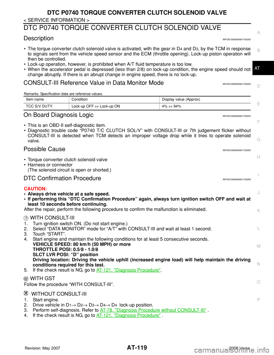
DescriptionINFOID:0000000001703252
• The torque converter clutch solenoid valve is activated, with the gear in D4 and D3, by the TCM in response
to signals sent from the vehicle speed sensor and the ECM (throttle opening). Lock-up piston operation will
then be controlled.
• Lock-up operation, however, is prohibited when A/T fluid temperature is too low.
• When the accelerator pedal is depressed (less than 2/8) on lock-up condition, the engine speed should not
change abruptly. If there is an abrupt change in engine speed, there is no lock-up.
CONSULT-III Reference Value in Data Monitor ModeINFOID:0000000001703253
Remarks: Specification data are reference values.
On Board Diagnosis LogicINFOID:0000000001703254
• This is an OBD-II self-diagnostic item.
• Diagnostic trouble code “P0740 T/C CLUTCH SOL/V” with CONSULT-III or 7th judgement flicker without
CONSULT-III is detected when TCM detects an improper voltage drop while it tries to operate solenoid
valve.
Possible CauseINFOID:0000000001703255
• Torque converter clutch solenoid valve
• Harness or connector
(The solenoid circuit is open or shorted.)
DTC Confirmation ProcedureINFOID:0000000001703256
CAUTION:
• Always drive vehicle at a safe speed.
• If performing this “DTC Confirmation Procedure” again, always turn ignition switch OFF and wait at
least 10 seconds before continuing.
After the repair, perform the following procedure to confirm the malfunction is eliminated.
WITH CONSULT-III
1. Turn ignition switch ON. (Do not start engine.)
2. Select “DATA MONITOR” mode for “A/T” with CONSULT-III and wait at least 1 second.
3. Touch “START”.
4. Start engine and maintain the following conditions for at least 5 consecutive seconds.
VEHICLE SPEED: 80 km/h (50 MPH) or more
THROTTLE POSI: 0.5/8 - 1.0/8
SLCT LVR POSI: “D” position
Driving location: Driving the vehicle uphill (increased engine load) will help maintain the driving
conditions required for this test.
5. If the check result is NG, go to AT-121, "
Diagnosis Procedure".
WITH GST
Follow the procedure “WITH CONSULT-III”.
WITHOUT CONSULT-III
1. Start engine.
2. Drive vehicle in D
1→ D2→ D3→ D4→ D4 lock-up position.
3. Perform self-diagnosis. Refer to AT-78, "
Diagnosis Procedure without CONSULT-III" .
4. If the check result is NG, go to AT-121, "
Diagnosis Procedure" .
Item name Condition Display value (Approx)
TCC S/V DUTY Lock-up OFF ⇔ Lock-up ON 4% ⇔ 94%
Page 133 of 2771
DTC P0740 TORQUE CONVERTER CLUTCH SOLENOID VALVE
AT-121
< SERVICE INFORMATION >
D
E
F
G
H
I
J
K
L
MA
B
AT
N
O
P
Diagnosis ProcedureINFOID:0000000001703258
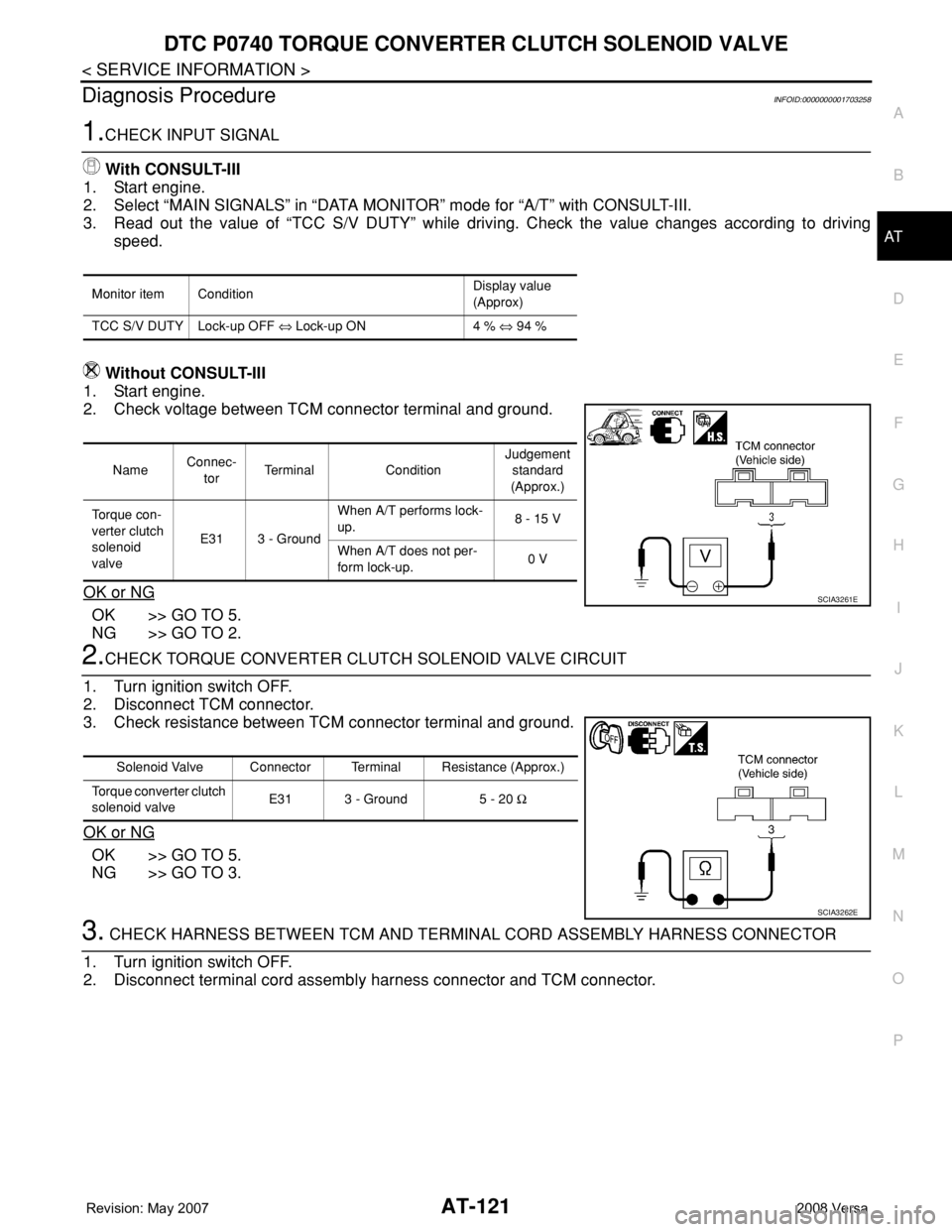
1.CHECK INPUT SIGNAL
With CONSULT-III
1. Start engine.
2. Select “MAIN SIGNALS” in “DATA MONITOR” mode for “A/T” with CONSULT-III.
3. Read out the value of “TCC S/V DUTY” while driving. Check the value changes according to driving
speed.
Without CONSULT-III
1. Start engine.
2. Check voltage between TCM connector terminal and ground.
OK or NG
OK >> GO TO 5.
NG >> GO TO 2.
2.CHECK TORQUE CONVERTER CLUTCH SOLENOID VALVE CIRCUIT
1. Turn ignition switch OFF.
2. Disconnect TCM connector.
3. Check resistance between TCM connector terminal and ground.
OK or NG
OK >> GO TO 5.
NG >> GO TO 3.
3. CHECK HARNESS BETWEEN TCM AND TERMINAL CORD ASSEMBLY HARNESS CONNECTOR
1. Turn ignition switch OFF.
2. Disconnect terminal cord assembly harness connector and TCM connector.
Monitor item ConditionDisplay value
(Approx)
TCC S/V DUTY Lock-up OFF ⇔ Lock-up ON 4 % ⇔ 94 %
NameConnec-
torTerminal ConditionJudgement
standard
(Approx.)
To r q u e c o n -
verter clutch
solenoid
valveE31 3 - GroundWhen A/T performs lock-
up.8 - 15 V
When A/T does not per-
form lock-up.0 V
SCIA3261E
Solenoid Valve Connector Terminal Resistance (Approx.)
Torque converter clutch
solenoid valveE31 3 - Ground 5 - 20 Ω
SCIA3262E
Page 136 of 2771

AT-124
< SERVICE INFORMATION >
DTC P0744 A/T TCC S/V FUNCTION (LOCK-UP)
DTC P0744 A/T TCC S/V FUNCTION (LOCK-UP)
DescriptionINFOID:0000000001703260
• This malfunction will not be detected while the OD OFF indicator lamp is indicating another self-diagnosis
malfunction.
• This malfunction is detected when the A/T does not shift into fourth gear position or the torque converter
clutch does not lock-up as instructed by the TCM. This is not caused by electrical malfunction (circuits open
or shorted) but by mechanical malfunction such as control valve sticking, improper solenoid valve operation,
malfunctioning oil pump or torque converter clutch, etc.
CONSULT-III Reference Value in Data Monitor ModeINFOID:0000000001703261
Remarks: Specification data are reference values.
On Board Diagnosis LogicINFOID:0000000001703262
• This is an OBD-II self-diagnostic item.
• Diagnostic trouble code “P0744 A/T TCC S/V FNCTN” with CONSULT-III is detected when A/T cannot per-
form lock-up even if electrical circuit is good.
• This diagnosis monitors actual gear position by checking the torque converter slip ratio calculated by TCM
as follows:
Torque converter slip ratio = A x C/B
A: Output shaft revolution signal from revolution sensor
B: Engine speed signal from ECM
C: Gear ratio determined as gear position which TCM supposes
If the actual gear position is much lower than the position (4th) supposed by TCM, the slip ratio will be much
less than normal. In case the ratio does not reach the specified value, TCM judges this diagnosis malfunc-
tion.
This malfunction will be caused when shift solenoid valve B is stuck closed.
• Gear positions supposed by TCM are as follows.
In case of gear position with no malfunctions: 1, 2, 3 and 4 positions
In case of gear position with shift solenoid valve B stuck closed: 1, 2, 2 and 1* positions to each gear position
above
*: “P0744 A/T TCC S/V FNCTN” is detected.
Possible CauseINFOID:0000000001703263
• Line pressure solenoid valve
• Torque converter clutch solenoid valve
• Each clutch
• Hydraulic control circuit
DTC Confirmation ProcedureINFOID:0000000001703264
CAUTION:
• Always drive vehicle at a safe speed.
• If performing this “DTC Confirmation Procedure” again, always turn ignition switch OFF and wait at
least 10 seconds before continuing.
After the repair, perform the following procedure to confirm the malfunction is eliminated.
WITH CONSULT-III
1. Start engine and select “DATA MONITOR” mode for “A/T” with CONSULT-III.
2. Touch “START”.
3. Make sure that output voltage of A/T fluid temperature sensor is within the range below.
FLUID TEMP SE: 0.4 - 1.5 V
If out of range, drive vehicle to decrease voltage (warm up the fluid) or stop engine to increase voltage
(cool down the fluid).
4. Select “TCC S/V FNCTN P0744” of “DTC WORK SUPPORT” mode for “A/T” with CONSULT-III and touch
“START”.
Item name Condition Display value (Approx)
TCC S/V DUTY Lock-up OFF ⇔ Lock-up ON 4% ⇔ 94%
Page 137 of 2771
DTC P0744 A/T TCC S/V FUNCTION (LOCK-UP)
AT-125
< SERVICE INFORMATION >
D
E
F
G
H
I
J
K
L
MA
B
AT
N
O
P
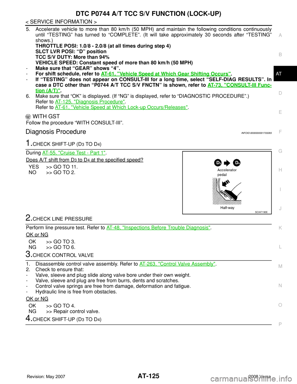
5. Accelerate vehicle to more than 80 km/h (50 MPH) and maintain the following conditions continuously
until “TESTING” has turned to “COMPLETE”. (It will take approximately 30 seconds after “TESTING”
shows.)
THROTTLE POSI: 1.0/8 - 2.0/8 (at all times during step 4)
SLCT LVR POSI: “D” position
TCC S/V DUTY: More than 94%
VEHICLE SPEED: Constant speed of more than 80 km/h (50 MPH)
-Make sure that “GEAR” shows “4”.
-For shift schedule, refer to AT-61, "
Vehicle Speed at Which Gear Shifting Occurs".
-If “TESTING” does not appear on CONSULT-III for a long time, select “SELF-DIAG RESULTS”. In
case a DTC other than “P0744 A/T TCC S/V FNCTN” is shown, refer to AT-73, "
CONSULT-III Func-
tion (A/T)".
6. Make sure that “OK” is displayed. (If “NG” is displayed, refer to “DIAGNOSTIC PROCEDURE”.)
Refer to AT-125, "
Diagnosis Procedure".
Refer to AT-61, "
Vehicle Speed at Which Lock-up Occurs/Releases".
WITH GST
Follow the procedure “WITH CONSULT-III”.
Diagnosis ProcedureINFOID:0000000001703265
1.CHECK SHIFT-UP (D3 TO D4)
During AT-55, "
Cruise Test - Part 1".
Does A/T shift from D
3 to D4 at the specified speed?
YES >> GO TO 11.
NO >> GO TO 2.
2.CHECK LINE PRESSURE
Perform line pressure test. Refer to AT-48, "
Inspections Before Trouble Diagnosis".
OK or NG
OK >> GO TO 3.
NG >> GO TO 6.
3.CHECK CONTROL VALVE
1. Disassemble control valve assembly. Refer to AT-263, "
Control Valve Assembly".
2. Check to ensure that:
- Valve, sleeve and plug slide along valve bore under their own weight.
- Valve, sleeve and plug are free from burrs, dents and scratches.
- Control valve springs are free from damage, deformation and fatigue.
- Hydraulic line is free from obstacles.
OK or NG
OK >> GO TO 4.
NG >> Repair control valve.
4.CHECK SHIFT-UP (D3 TO D4)
SCIA7190E