NISSAN LATIO 2009 Service Repair Manual
LATIO 2009
NISSAN
NISSAN
https://www.carmanualsonline.info/img/5/57359/w960_57359-0.png
NISSAN LATIO 2009 Service Repair Manual
Trending: air filter, transmission fluid, water pump, glove box, child lock, engine overheat, engine oil capacity
Page 1091 of 4331
CVT
N
O P
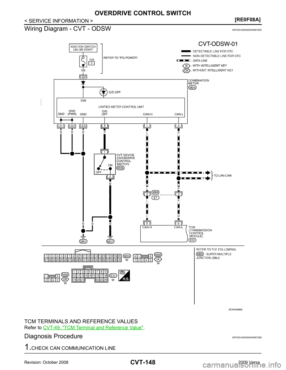
OVERDRIVE CONTROL SWITCH
Description INFOID:0000000004667083
• Overdrive control switch is installed to the selector lever.
• O/D OFF indicator turns ON, and overdrive driving activates when pressing the overdrive control switch while driving in “D” position. O/D OFF indicator turns OFF, and “D” position driving starts when pressing the
overdrive control switch while driving in the overdriv e-off mode. Shifting the selector lever in any position
other than “D” releases the overdrive-off mode.
CONSULT-III Reference Val ue in Data Monitor Mode INFOID:0000000004667084
Item name Condition Display value
SPORT MODE SW While pushing overdrive cancel switch ON
Other conditions OFF
Page 1092 of 4331
TCM Terminal and Reference Value " .
Diagnosis Procedure INFOID:0000000004667086
Page 1093 of 4331
CVT
N
O P
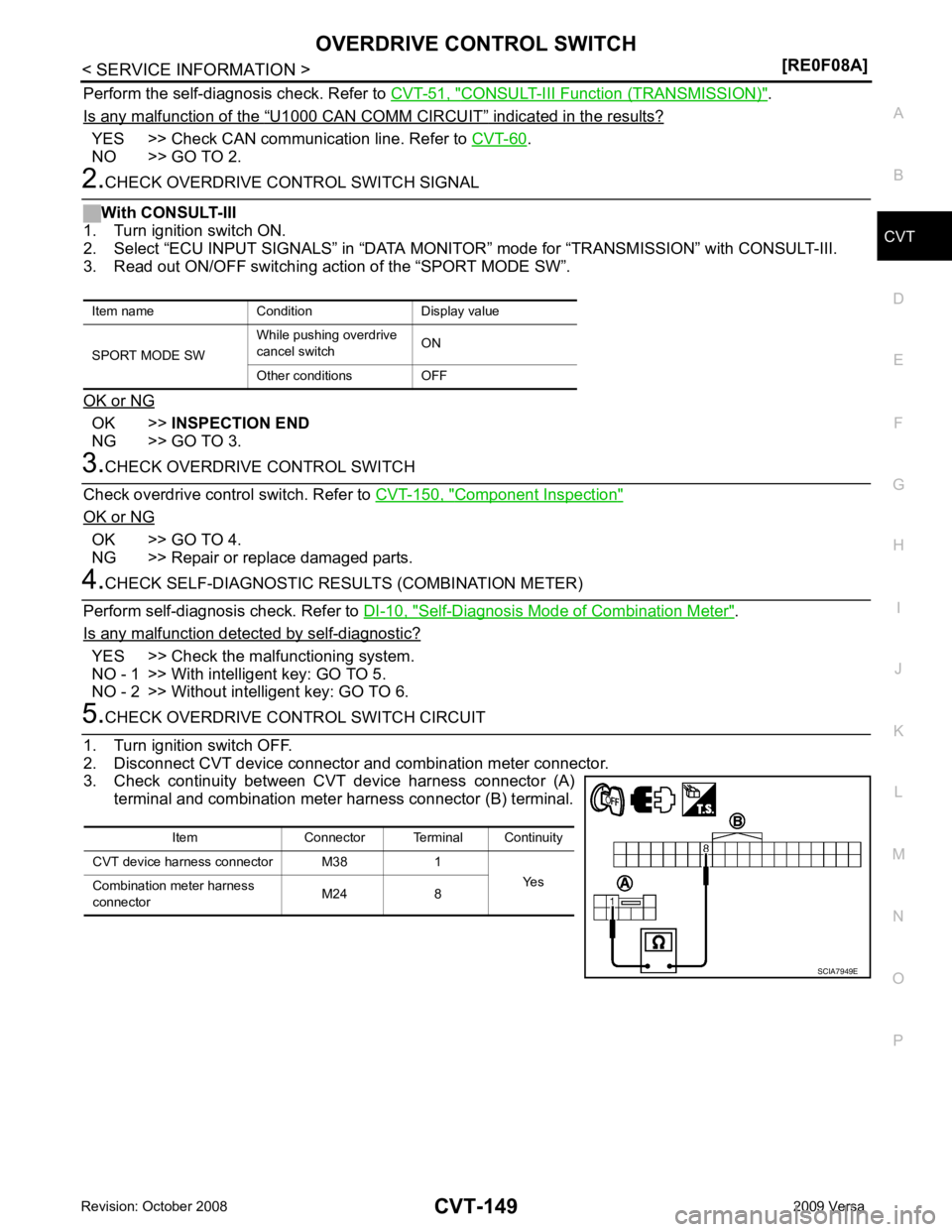
Perform the self-diagnosis check. Refer to
CVT-51, " CONSULT-III Functi
on (TRANSMISSION) " .
Is any malfunction of the “ U1000 CAN COMM CIRCUIT ” indicated in the results?
YES >> Check CAN communication line. Refer to
CVT-60 .
NO >> GO TO 2. OK >>
INSPECTION END
NG >> GO TO 3. Component Inspection "
OK or NG
OK >> GO TO 4.
NG >> Repair or replace damaged parts. Self-Diagnosis Mode of Combination Meter " .
Is any malfunction detected by self-diagnostic? YES >> Check the malfunctioning system.
NO - 1 >> With intelligent key: GO TO 5.
NO - 2 >> Without intelligent key: GO TO 6. Item Connector Terminal Continuity
CVT device harness connector M38 1 Yes
Combination meter harness
connector M24 8
Page 1094 of 4331
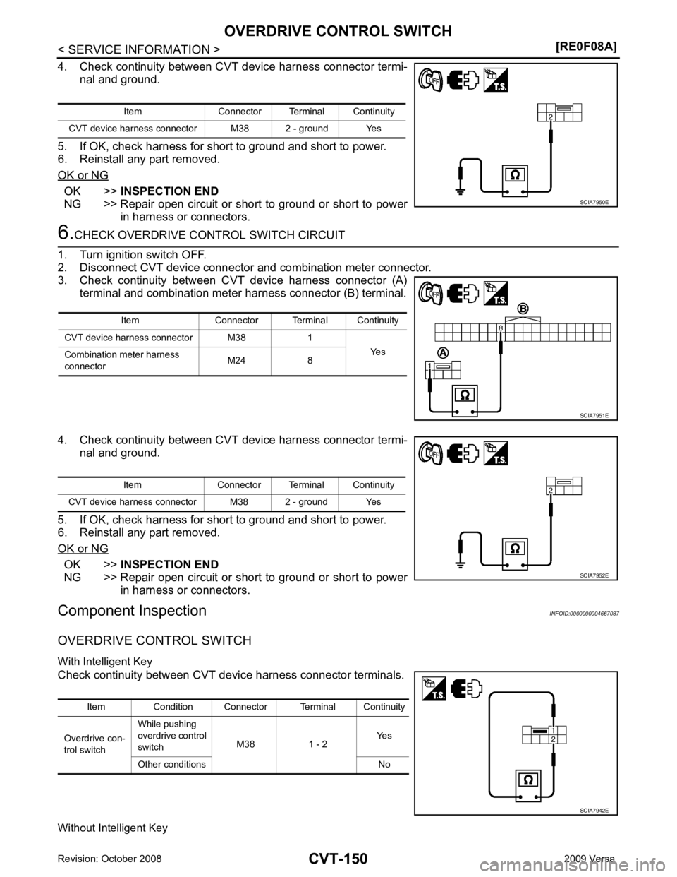
OK >>
INSPECTION END
NG >> Repair open circuit or short to ground or short to power
in harness or connectors. OK >>
INSPECTION END
NG >> Repair open circuit or short to ground or short to power in harness or connectors.
Component Inspection INFOID:0000000004667087
OVERDRIVE CONTROL SWITCH
With Intelligent Key
Check continuity between CVT device harness connector terminals.
Without Intelligent Key Item Connector Terminal Continuity
CVT device harness connector M38 2 - ground Yes
Page 1095 of 4331
CVT
N
O P
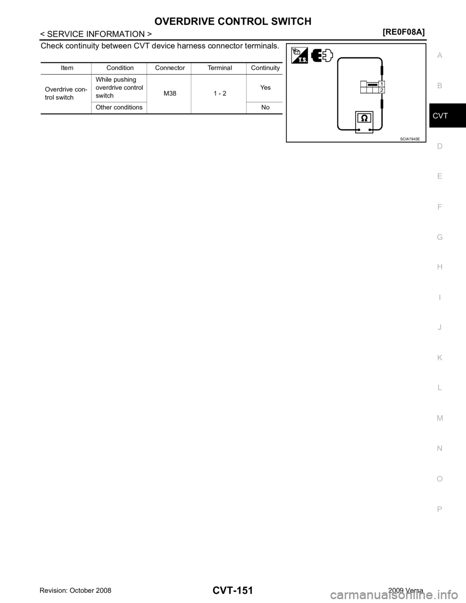
Check continuity between CVT dev
ice harness connector terminals.
Item Condition Connector Terminal Continuity
Overdrive con-
trol switch While pushing
overdrive control
switch M38 1 - 2 Yes
Other conditions No
Page 1096 of 4331
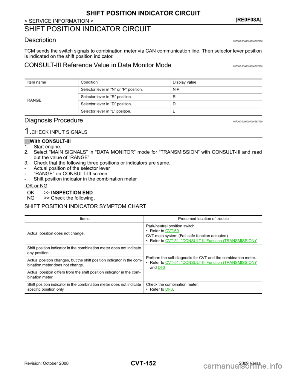
OK >>
INSPECTION END
NG >> Check the following.
SHIFT POSITION INDICATOR SYMPTOM CHART Item name Condition Display value
RANGE Selector lever in “N
” or “P” position. N·P
Selector lever in “R” position. R
Selector lever in “D” position. D
Selector lever in “L” position. L Items Presumed location of trouble
Actual position does not change. Park/neutral position switch
• Refer to CVT-69 .
CVT main system (Fail-safe function actuated)
• Refer to CVT-51, " CONSULT-III Function (TRANSMISSION) " .
Shift position indicator in the combination meter does not indicate
any position. Perform the self-diagnosis for CVT and the combination meter.
• Refer to CVT-51, " CONSULT-III Function (TRANSMISSION) "
and DI-3 .
Actual position changes, but the shift position indicator in the com-
bination meter does not change.
Actual position differs from the shift position indicator in the com-
bination meter.
Shift position indicator in the combination meter does not indicate
specific position only. Check the combination meter.
• Refer to DI-3 .
Page 1097 of 4331
CVT
N
O P
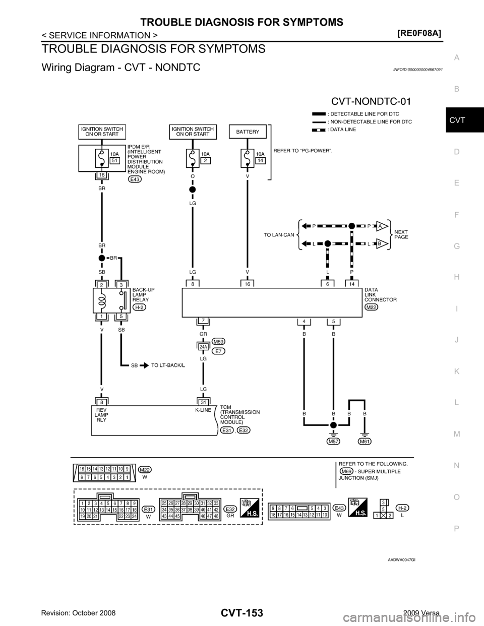
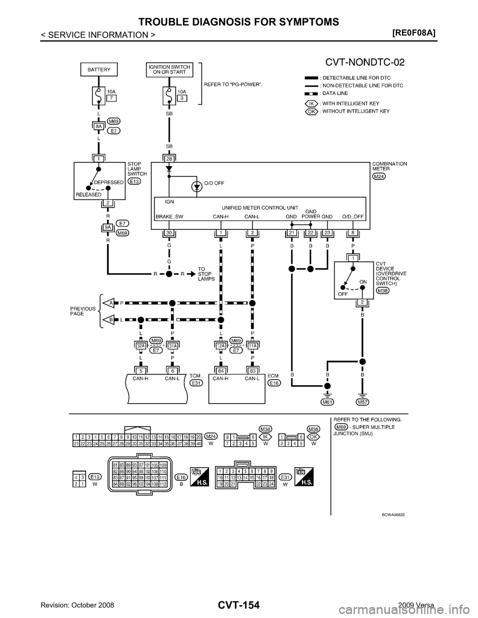
TROUBLE DIAGNOSIS FOR SYMPTOMS
Wiring Diagram - CVT - NONDTC INFOID:0000000004667091 B
Page 1098 of 4331
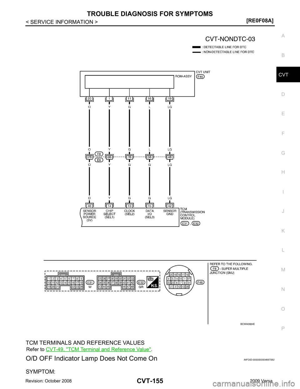
Page 1099 of 4331
CVT
N
O P
TCM TERMINALS AND REFERENCE VALUES Refer to CVT-49, " TCM Terminal and Reference Value " .
O/D OFF Indicator Lamp Does Not Come On INFOID:0000000004667092
SYMPTOM:
Page 1100 of 4331
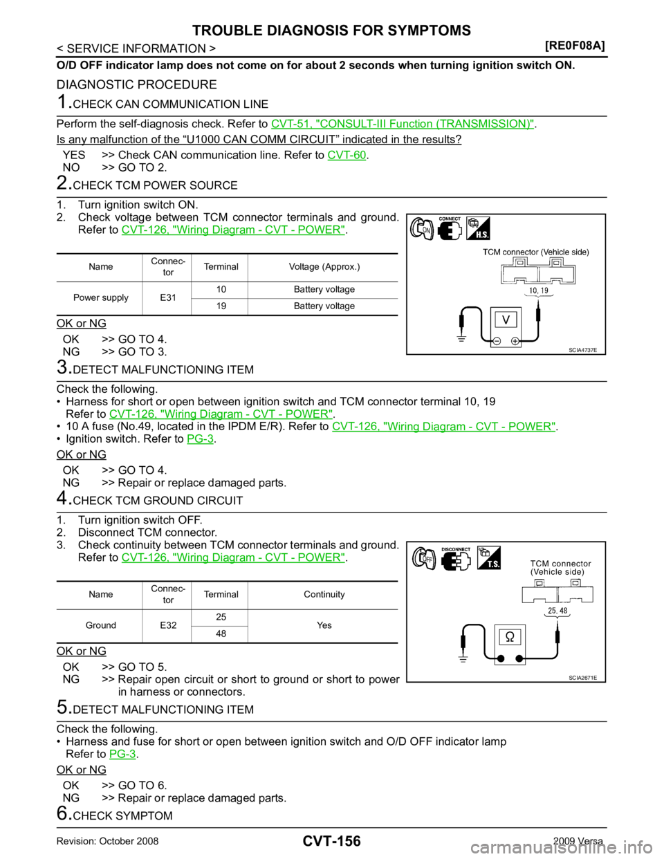
CONSULT-III Function (TRANSMISSION) " .
Is any malfunction of the “ U1000 CAN COMM CIRCUIT ” indicated in the results?
YES >> Check CAN communication line. Refer to
CVT-60 .
NO >> GO TO 2. Wiring Diagram - CVT - POWER " .
OK or NG OK >> GO TO 4.
NG >> GO TO 3. Wiring Diagram - CVT - POWER " .
• 10 A fuse (No.49, located in the IPDM E/R). Refer to CVT-126, " Wiring Diagram - CVT - POWER " .
• Ignition switch. Refer to PG-3 .
OK or NG OK >> GO TO 4.
NG >> Repair or replace damaged parts. Wiring Diagram - CVT - POWER " .
OK or NG OK >> GO TO 5.
NG >> Repair open circuit or short to ground or short to power
in harness or connectors. .
OK or NG OK >> GO TO 6.
NG >> Repair or replace damaged parts.
Trending: maintenance, fuel consumption, jack points, audio, checking oil, key fob battery, height adjustment

