NISSAN LATIO 2009 Service Repair Manual
LATIO 2009
NISSAN
NISSAN
https://www.carmanualsonline.info/img/5/57359/w960_57359-0.png
NISSAN LATIO 2009 Service Repair Manual
Trending: ad blue, fuel consumption, check oil, oil temperature, fuse box, turn signal, brake
Page 1301 of 4331
CVT
N
O P
SERVICE DATA AND SPECIFICATIONS (SDS)
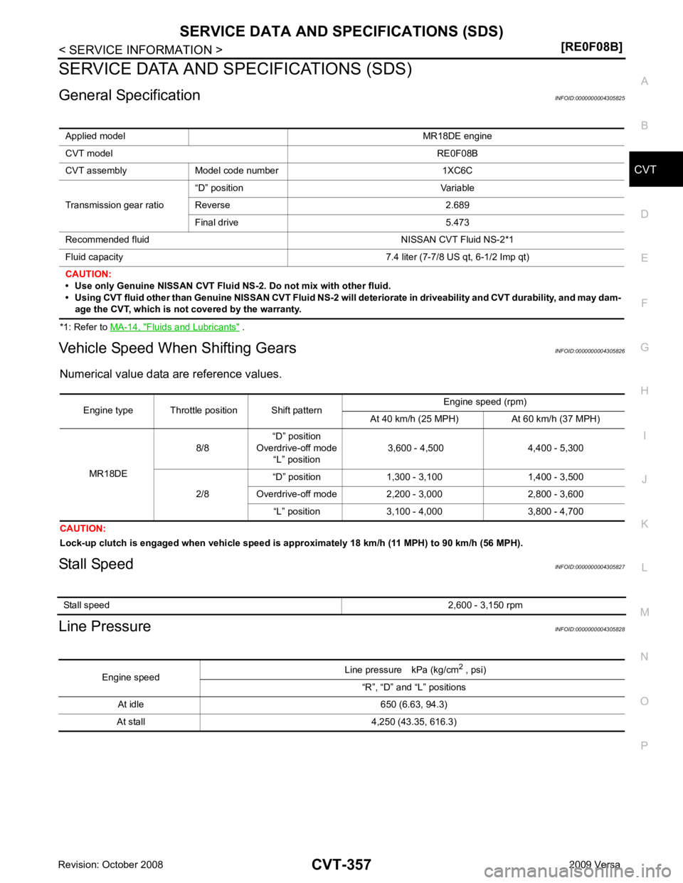
General Specification INFOID:0000000004305825
*1: Refer to MA-14, " Fluids and Lubricants " .
Vehicle Speed When Shifting Gears INFOID:0000000004305826
Numerical value data are reference values.
CAUTION:
Lock-up clutch is engaged when vehi cle speed is approximately 18 km/h (11 MPH) to 90 km/h (56 MPH).
Stall Speed INFOID:0000000004305827
Line Pressure INFOID:0000000004305828
Applied model
MR18DE engine
CVT model RE0F08B
CVT assembly Model code number 1XC6C
Transmission gear ratio “D” position Variable
Reverse 2.689
Final drive 5.473
Recommended fluid NISSAN CVT Fluid NS-2*1
Fluid capacity 7.4 liter (7-7/8 US qt, 6-1/2 Imp qt)
CAUTION:
• Use only Genuine NISSAN CVT Fluid NS-2. Do not mix with other fluid.
• Using CVT fluid other than Genuine NISSAN CVT Fluid NS-2 will deteriorate in driveability and CVT durability, and may dam- age the CVT, which is not covered by the warranty. Stall speed
2,600 - 3,150 rpmEngine speed
Line pressure kPa (kg/cm
2
, psi)
“R”, “D” and “L” positions
At idle 650 (6.63, 94.3)
At stall 4,250 (43.35, 616.3)
Page 1302 of 4331
Name Condition CONSULT-III “DATA MONI
TOR” (Approx.) Resistance (Approx.)
ATF TEMP SEN 20
°C (68 °F) 2.0 V 6.5 k Ω
80 °C (176 °F) 1.0 V 0.9 k ΩName Condition Data (Approx.)
Secondary speed sensor When driving [
Page 1303 of 4331
DI
N
O P
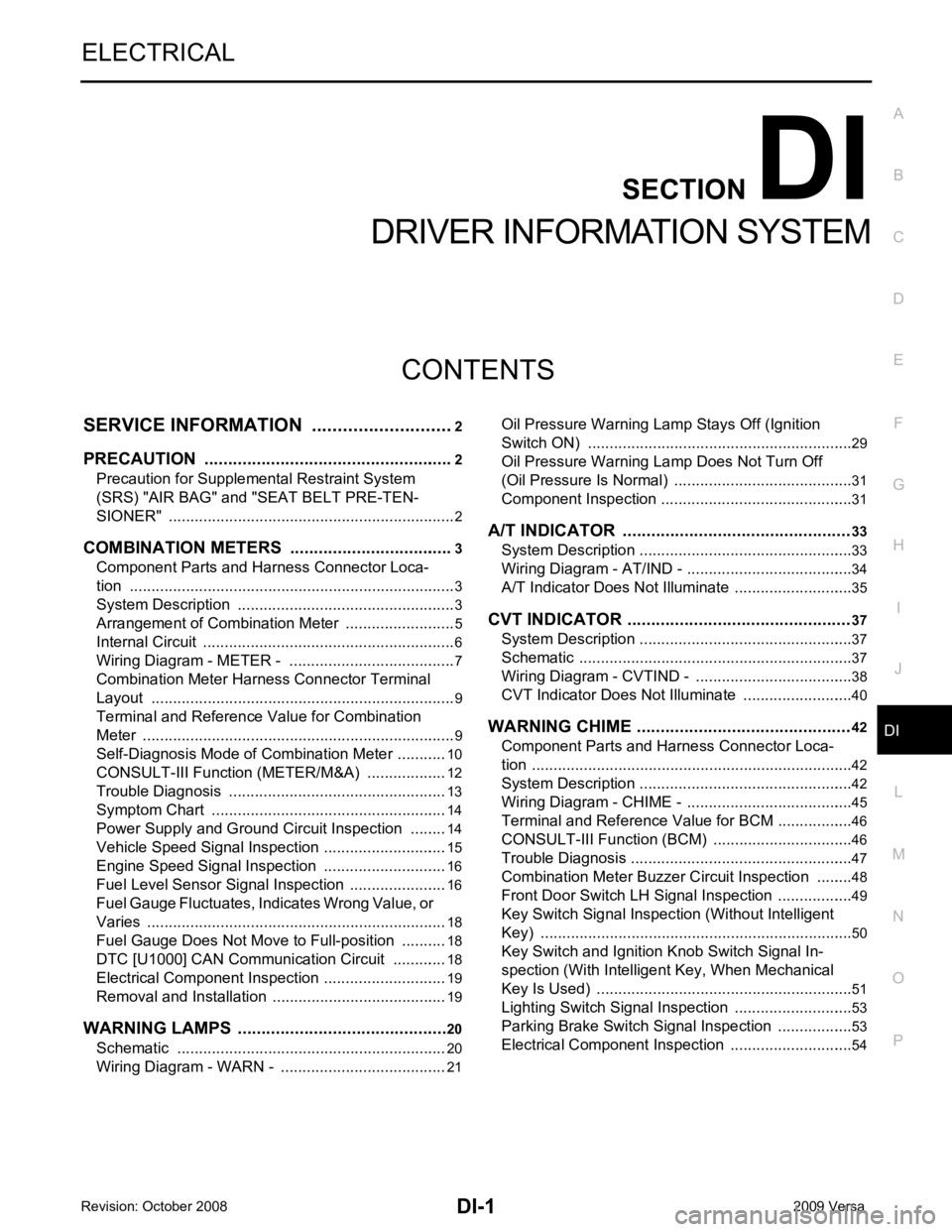
CONTENTS
DRIVER INFORMATION SYSTEM
SERVICE INFORMATION .. ..........................2
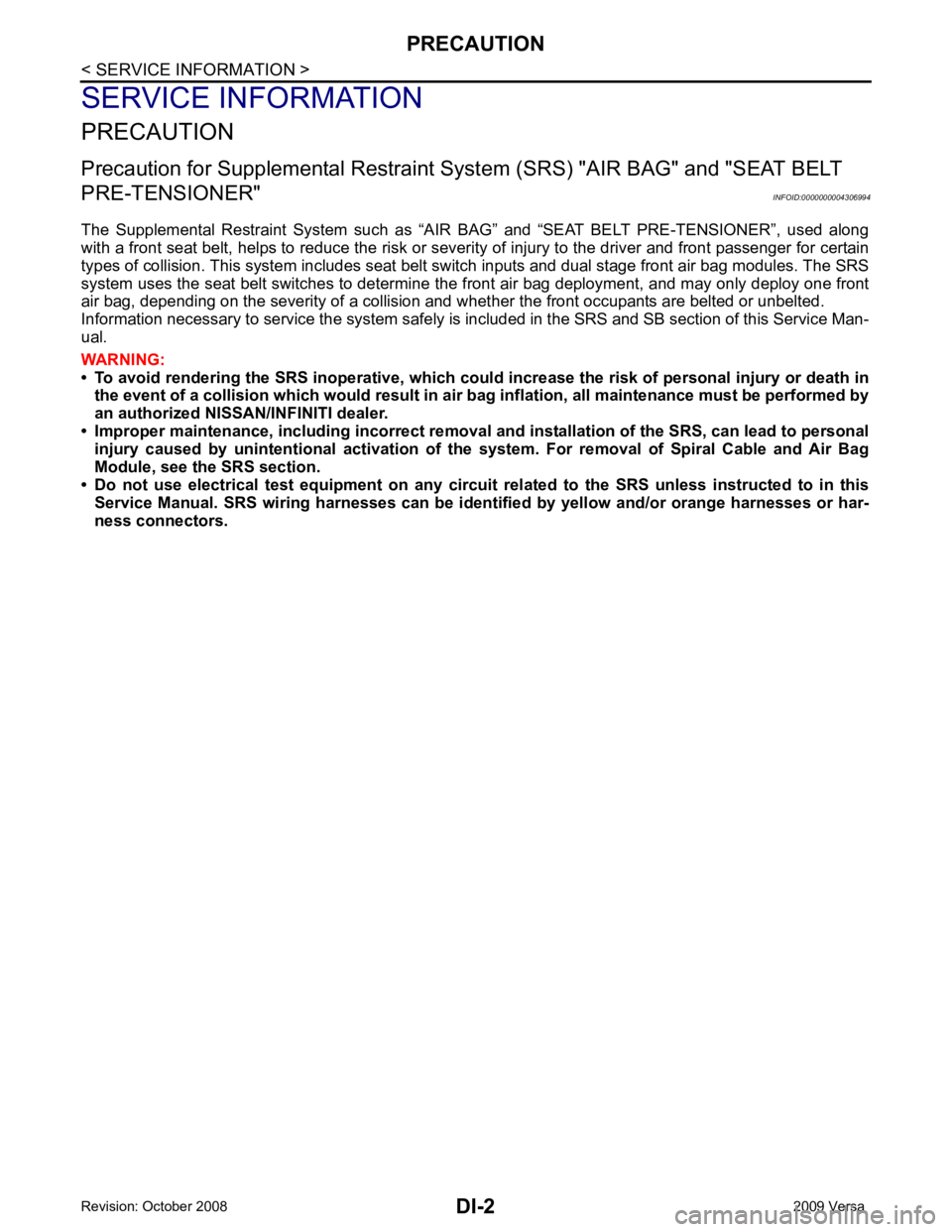
PRECAUTION ................................................ .....2
Precaution for Supplemental Restraint System
(SRS) "AIR BAG" and "SEAT BELT PRE-TEN-
SIONER" ............................................................. ......
2
COMBINATION METERS .............................. .....3
Component Parts and Harness Connector Loca-
tion ...................................................................... ......
3
System Description ............................................. ......3
Arrangement of Combination Meter .................... ......5
Internal Circuit ..................................................... ......6
Wiring Diagram - METER - ................................. ......7
Combination Meter Harness Connector Terminal
Layout ................................................................. ......
9
Terminal and Reference Value for Combination
Meter ................................................................... ......
9
Self-Diagnosis Mode of Combination Meter ........ ....10
CONSULT-III Function (METER/M&A) ............... ....12
Trouble Diagnosis ............................................... ....13
Symptom Chart ................................................... ....14
Power Supply and Ground Circuit Inspection ..... ....14
Vehicle Speed Signal Inspection ......................... ....15
Engine Speed Signal Inspection ......................... ....16
Fuel Level Sensor Signal Inspection ................... ....16
Fuel Gauge Fluctuates, Indicates Wrong Value, or
Varies .................................................................. ....
18
Fuel Gauge Does Not Move to Full-position ...........18
DTC [U1000] CAN Communication Circuit ......... ....18
Electrical Component Inspection ......................... ....19
Removal and Installation .........................................19
WARNING LAMPS ......................................... ....20
Schematic ........................................................... ....20
Wiring Diagram - WARN - ................................... ....21 Oil Pressure Wa
rning Lamp Stays Off (Ignition
Switch ON) .......................................................... ....
29
Oil Pressure Wa rning Lamp Does Not Turn Off
(Oil Pressure Is Normal) ...................................... ....
31
Component Inspection ......................................... ....31
A/T INDICATOR ................................................ 33
System Description .............................................. ....33
Wiring Diagram - AT/IND - ................................... ....34
A/T Indicator Does Not Illuminate ........................ ....35
CVT INDICATOR ............................................... 37
System Description .............................................. ....37
Schematic ............................................................ ....37
Wiring Diagram - CVTIND - ................................. ....38
CVT Indicator Does Not Illuminate ...................... ....40
WARNING CHIME ............................................. 42
Component Parts and Harness Connector Loca-
tion ....................................................................... ....
42
System Description .............................................. ....42
Wiring Diagram - CHIME - ................................... ....45
Terminal and Reference Value for BCM ..................46
CONSULT-III Function (B CM) .................................46
Trouble Diagnosis ................................................ ....47
Combination Meter Buzzer Cir cuit Inspection .........48
Front Door Switch LH Signal Inspection .............. ....49
Key Switch Signal Inspec tion (Without Intelligent
Key) ..................................................................... ....
50
Key Switch and Ignition Knob Switch Signal In-
spection (With Intelligent Key, When Mechanical
Key Is Used) ........................................................ ....
51
Lighting Switch Signal Inspection ........................ ....53
Parking Brake Switch Signal Inspection .............. ....53
Electrical Component Inspection ......................... ....54
Page 1304 of 4331
Page 1305 of 4331
DI
N
O P
COMBINATION METERS
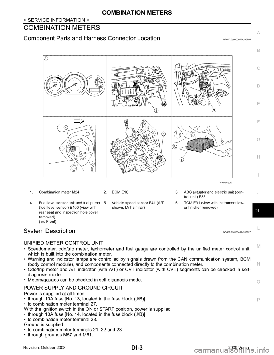
Component Parts and Har ness Connector Location INFOID:0000000004306996
System Description INFOID:0000000004306997
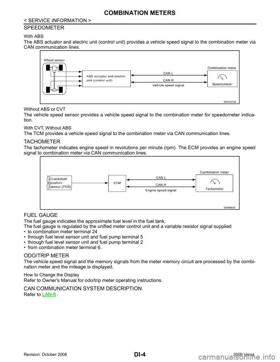
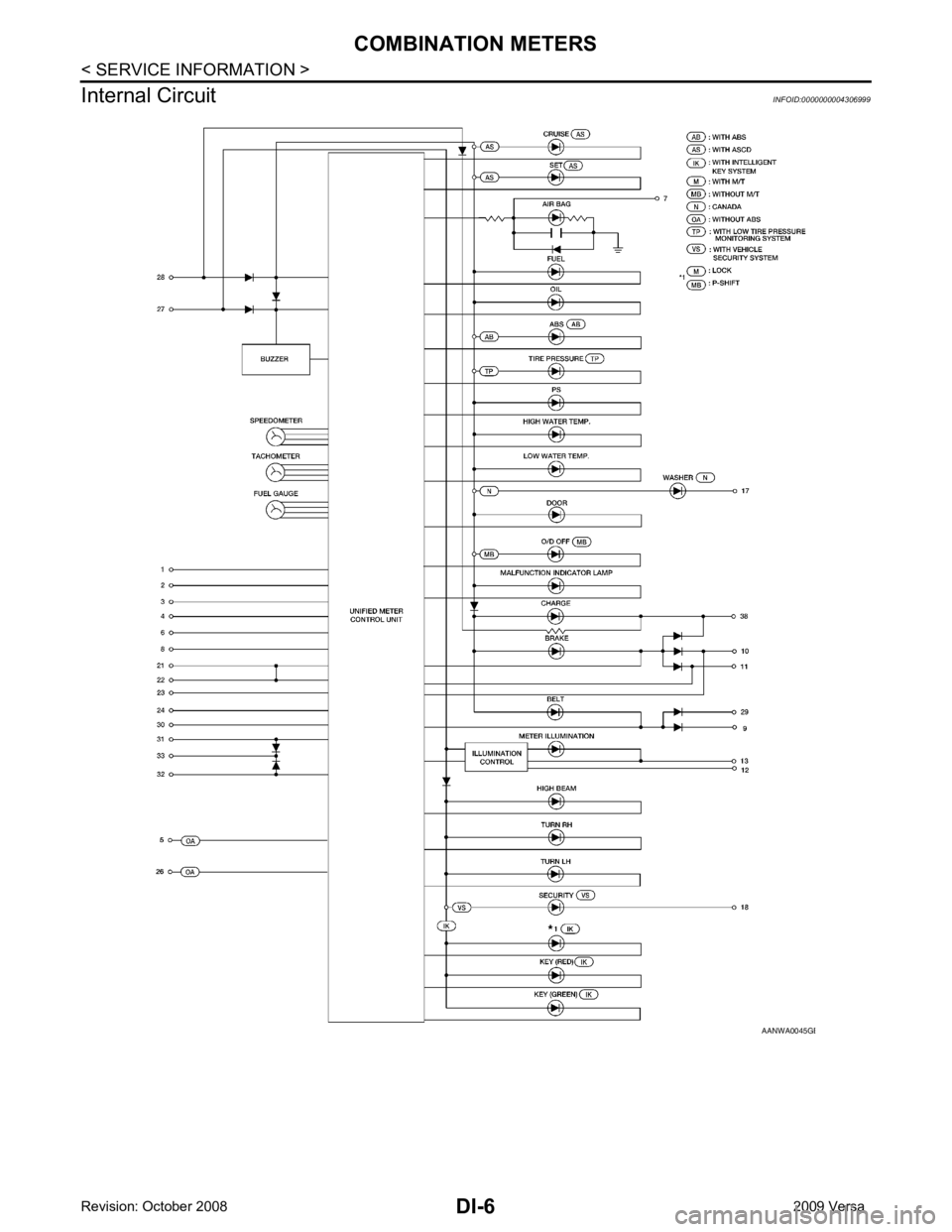
UNIFIED METER CONTROL UNIT • Speedometer, odo/trip meter, tachometer and fuel gauge are controlled by the unified meter control unit,
which is built into the combination meter.
• Warning and indicator lamps are controlled by signal s drawn from the CAN communication system, BCM
(body control module), and components connected directly to the combination meter.
• Odo/trip meter and A/T indicator (with A/T) or CVT i ndicator (with CVT) segments can be checked in self-
diagnosis mode.
• Meters/gauges can be checked in self-diagnosis mode.
POWER SUPPLY AND GROUND CIRCUIT Power is supplied at all times
• through 10A fuse [No. 13, located in the fuse block (J/B)]
• to combination meter terminal 27.
With the ignition switch in the ON or START position, power is supplied
• through 10A fuse [No. 14, located in the fuse block (J/B)]
• to combination meter terminal 28.
Ground is supplied
• to combination meter terminals 21, 22 and 23
• through grounds M57 and M61. 1. Combination meter M24 2. ECM E16 3. ABS actuator and electric unit (con-
trol unit) E33
4. Fuel level sensor unit and fuel pump (fuel level sensor) B100 (view with
rear seat and inspection hole cover
removed)
( ⇐ : Front) 5. Vehicle speed sensor F41 (A/T
shown, M/T similar) 6. TCM E31 (view with
instrument low-
er finisher removed)
Page 1306 of 4331
Page 1307 of 4331
DI
N
O P
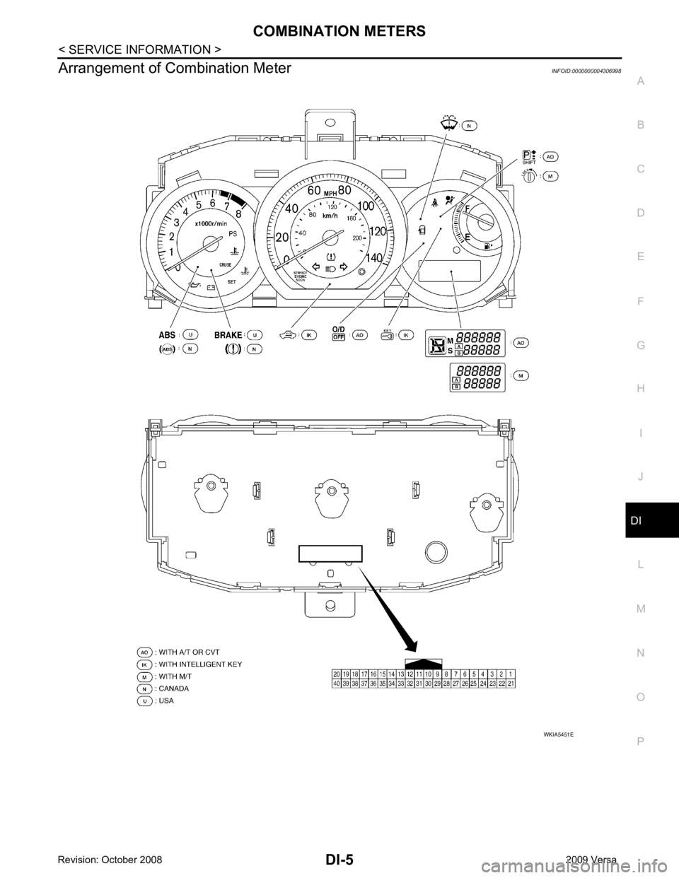
Arrangement of Combination Meter
INFOID:0000000004306998
Page 1308 of 4331
Page 1309 of 4331
DI
N
O P
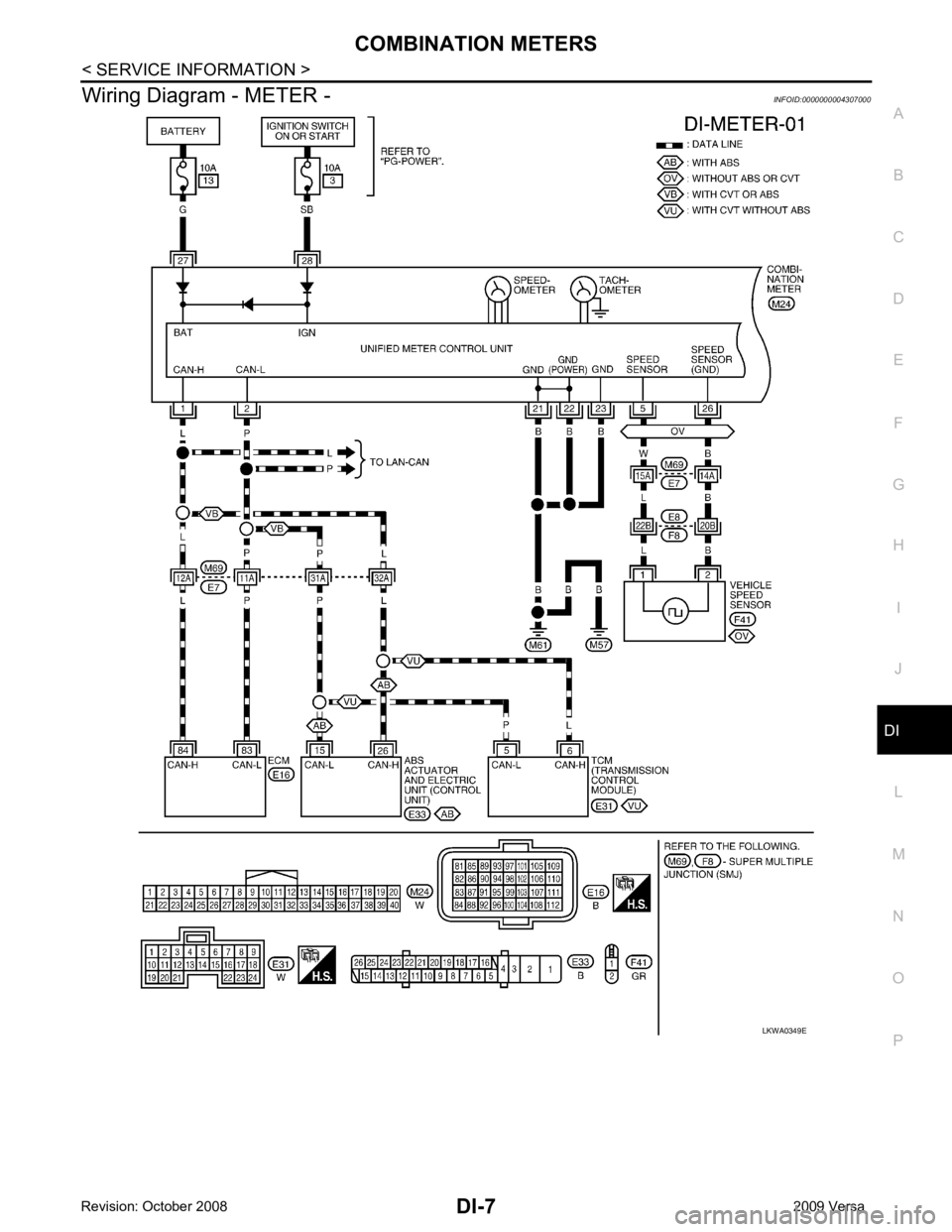
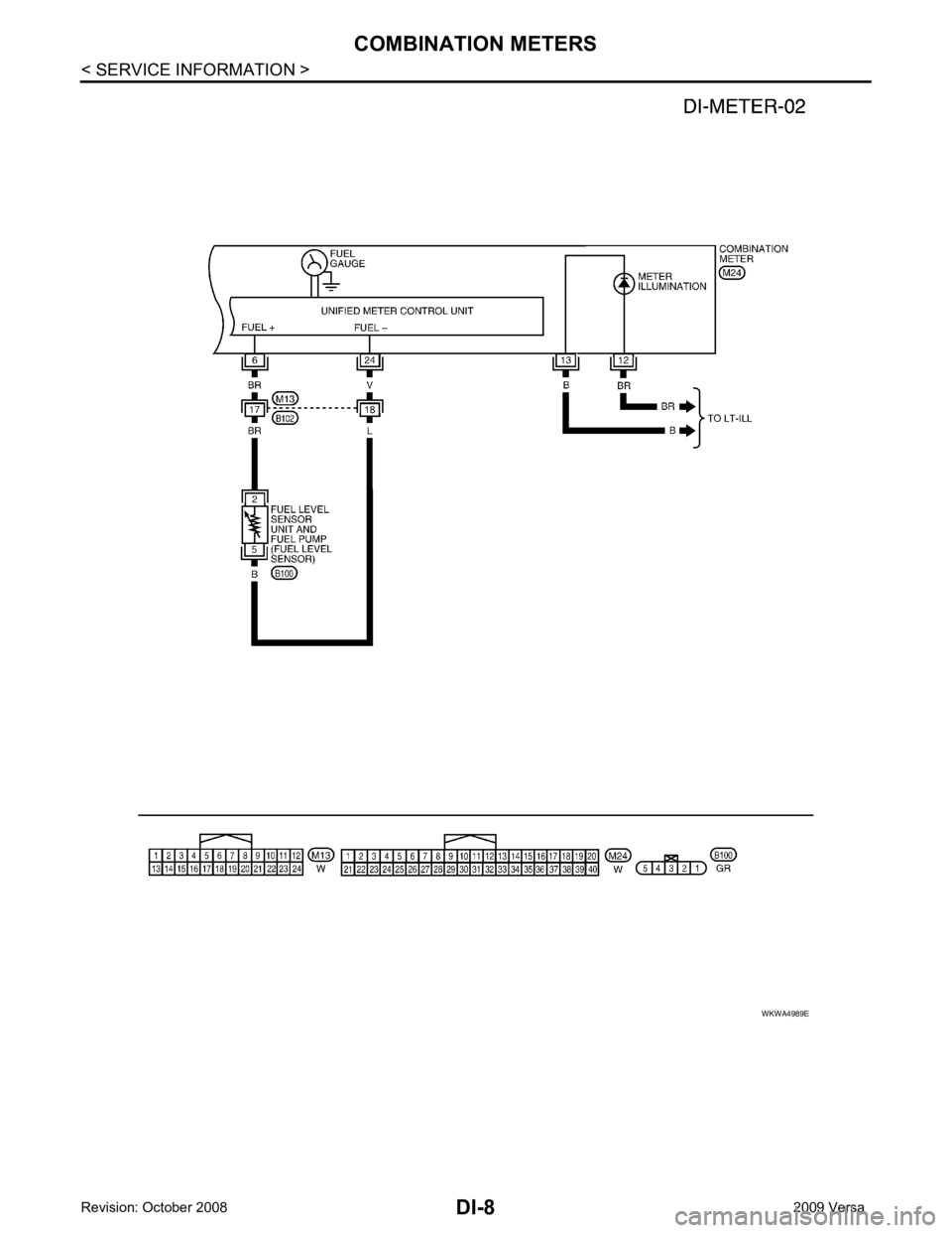
Wiring Diagram - METER -
INFOID:0000000004307000
Page 1310 of 4331
Trending: turn signal bulb, wheel bolt torque, tire pressure, service indicator, automatic transmission fluid, fuse box, overheating


