NISSAN LATIO 2009 Service Repair Manual
Manufacturer: NISSAN, Model Year: 2009, Model line: LATIO, Model: NISSAN LATIO 2009Pages: 4331, PDF Size: 58.04 MB
Page 1311 of 4331
DI
N
O P
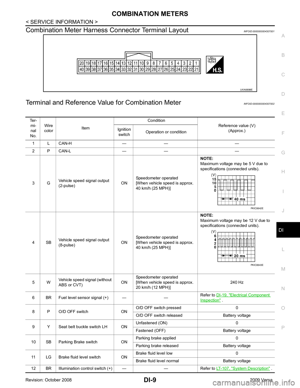
Combination Meter Harness Connector Terminal Layout
INFOID:0000000004307001
Terminal and Reference Va lue for Combination Meter INFOID:0000000004307002 Electrical Component
Inspection " .
8 P O/D OFF switch ON O/D OFF switch pressed 0
O/D OFF switch released Battery voltage
9 Y Seat belt buckle switch LH ON Unfastened (ON) 0
Fastened (OFF) Battery voltage
10 SB Parking Brake switch ON Parking brake applied 0
Parking brake released Battery voltage
11 LG Brake fluid level switch ON Brake fluid level low 0
Brake fluid level normal Battery voltage
12 BR Illumination control switch (+) — — Refer to LT-107, " System Description " .
Page 1312 of 4331
System Description " .
17 G Washer fluid level switch
(Canada models) ONWasher fluid level low 0
Washer fluid level normal Battery voltage
21 B Ground — — 0
22
23
24 V Fuel level sensor ground (-) ON — 0
26 B Vehicle speed sensor ground
(without ABS or CVT) ON — 0
27 G Battery power supply OFF — Battery voltage
28 SB Ignition switch ON or START ON — Battery voltage
29 GR Seat belt buckle switch RH ON Unfastened (ON) 0
Fastened (OFF) Battery voltage
30 G Stop lamp switch ON Brake pedal depressed Battery voltage
Brake pedal released 0
31 V A/T N-range input (with A/T) ON Transmission gear selector lever
in N position Battery voltage
Transmission gear selector lever
other than N position 0
32 W A/T P-range input (with A/T) ON Transmission gear selector lever
in P position Battery voltage
Transmission gear selector lever
other than P position 0
33 Y A/T PN output (with A/T) ON Transmission gear selector lever
in P or N position 0
Transmission gear selector lever
other than P or N position Battery voltage
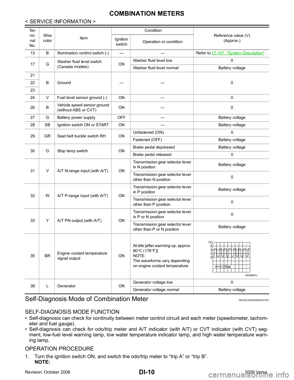
35 BR Engine coolant temperature
signal output ONAt idle [after warming up, approx.
80 °C (176 °F)]
NOTE:
The waveforms vary depending
on engine coolant temperature.
38 L Generator ON Generator voltage low 0
Generator voltage normal Battery voltage
Ter-
mi-
nal
No. Wire
color Item Condition
Reference value (V)
(Approx.)
Ignition
switch Operation or condition
Page 1313 of 4331
DI
N
O P
If the diagnosis function is activat
ed with “trip A” displayed, the mileage on “trip A” will indicate “0000.0”,
but the actual trip mileage will be retained. (The same applies for “trip B”.)
2. Turn ignition switch OFF.
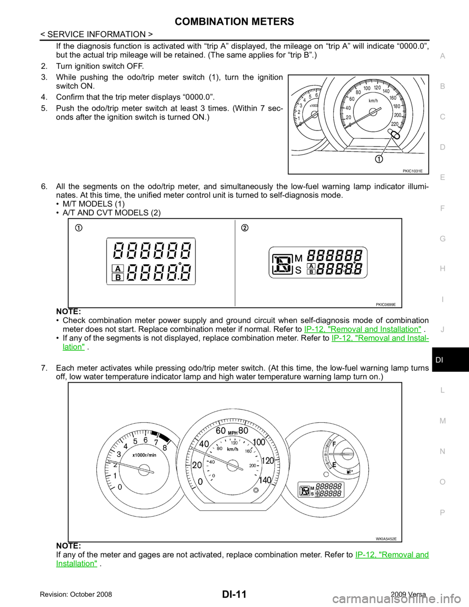
3. While pushing the odo/trip meter switch (1), turn the ignition switch ON.
4. Confirm that the trip meter displays “0000.0”.
5. Push the odo/trip meter switch at least 3 times. (Within 7 sec- onds after the ignition switch is turned ON.)
6. All the segments on the odo/trip meter, and simultaneously the low-fuel warning lamp indicator illumi- nates. At this time, the unified meter cont rol unit is turned to self-diagnosis mode.
• M/T MODELS (1)
• A/T AND CVT MODELS (2)
NOTE:
• Check combination meter power supply and ground circuit when self-diagnosis mode of combination
meter does not start. Replace combi nation meter if normal. Refer to IP-12, " Removal and Installation " .
• If any of the segments is not displayed, replace combination meter. Refer to IP-12, " Removal and Instal-
lation " .
7. Each meter activates while pressing odo/trip meter switch. (At this time, the low-fuel warning lamp turns off, low water temperature indicator lamp and high water temperature warning lamp turn on.)
NOTE:
If any of the meter and gages are not activat ed, replace combination meter. Refer to IP-12, " Removal and
Installation " .
Page 1314 of 4331
![NISSAN LATIO 2009 Service Repair Manual CONSULT-III display Malfunction Reference page
CAN COMM CIRC [U1000] Malfunction is detected in CAN communication lines.
CAUTION:
Even when there is no malfunct ion on CAN communication system, mal-
f NISSAN LATIO 2009 Service Repair Manual CONSULT-III display Malfunction Reference page
CAN COMM CIRC [U1000] Malfunction is detected in CAN communication lines.
CAUTION:
Even when there is no malfunct ion on CAN communication system, mal-
f](/img/5/57359/w960_57359-1313.png)
CONSULT-III display Malfunction Reference page
CAN COMM CIRC [U1000] Malfunction is detected in CAN communication lines.
CAUTION:
Even when there is no malfunct ion on CAN communication system, mal-
function may be misinterpreted when battery has low voltage (when main-
taining 7 - 8 V for about 2 seconds) or 10A fuse [No. 14, located in the fuse
block (J/B)] is removed. DI-18VEHICLE SPEED CIRC [B2205]
Malfunction is detected when an erroneous speed signal is input.
CAUTION:
Even when there is no malfunction on speed signal system, malfunctions
may be misinterpreted when battery has low voltage (when maintaining 7
- 8 V for about 2 seconds). DI-15Display item [Unit]
MAIN
SIGNALS SELECTION
FROM MENU Contents
SPEED METER [km/h] X X The value of vehicle speed sign
al, which is input from ABS ac-
tuator and electric unit (control unit).
SPEED OUTPUT [km/h] X X The value of vehicle speed signal, which is transmitted to each
unit with CAN communication.
TACHO METER [rpm] X X The value of engine speed signal, which is input from ECM.
W TEMP METER [ °C] X X The value of engine coolant temperature signal, which is input
from ECM.
FUEL METER [lit.] X X The value, which processes a resistance signal from fuel
gauge.
DISTANCE [km] X X The value, which is calculated by vehicle speed signal from
ABS actuator and electric unit (con trol unit), fuel gauge and fuel
consumption signal from ECM.
FUEL W/L [ON/OFF] X X Indicates [ON/OFF] condition of low-fuel warning lamp.
C-ENG W/L [ON/OFF] X Indicates [ON/OFF] condition of malfunction indicator lamp
(MIL).
AIR PRES W/L X Indicates [ON/OFF] condition of low tire pressure warning lamp.
SEAT BELT W/L X Indicates [ON/OFF] condition of seat belt warning lamp.
BUZZER [ON/OFF] X X Indicates [ON/ OFF] condition of buzzer.
DOOR W/L [ON/OFF] X Indicates [ON/OFF] condition of door warning lamp.
HI-BEAM IND [ON/OFF] X Indicat es [ON/OFF] condition of high beam indicator lamp.
Page 1315 of 4331

DI
N
O P
NOTE:
Some items are not available due to vehicle specification.
*: The monitor will indicate “OFF” even though the brake warnin g lamp is on if either of the following conditions exist.
• The parking brake is engaged
• The brake fluid level is low
Trouble Diagnosis INFOID:0000000004307005
HOW TO PERFORM TROUBLE DIAGNOSIS 1. Confirm the symptom or customer complaint.
2. Perform preliminary check. Refer to "PRELIMINARY CHECK" .
3. According to the symptom chart, repair or replace the cause of the malfunction. Refer to DI-14, " Symptom
Chart " .
4. Does the meter operate normally? If so, GO TO 5. If not, GO TO 2.
5. Inspection End.
PRELIMINARY CHECK Self-Diagnosis Mode of Combination Meter " .
Does self - diagnosis mode operate?
YES >> GO TO 2.
TURN IND [ON/OFF] X Indicates [ON/O
FF] condition of turn indicator.
OIL W/L [ON/OFF] X Indicates [ON/OFF] condition of oil pressure warning lamp.
ABS W/L [ON/OFF] X Indicates [ON/O FF] condition of ABS warning lamp.
BRAKE W/L [ON/OFF] X Indicates [ON/OFF] condition of brake warning lamp.*
KEY G W/L [ON/OFF] X Indicates [ON/OFF] condition of KEY warning lamp (green).
KEY R W/L [ON/OFF] X Indicates [ON/OFF] condition of KEY warning lamp (red).
KEY KNOB W/L [ON/OFF] X Indicates [ON/OFF] condition of LOCK warning lamp.
PNP P SW [ON/OFF] X X Indicates [ON/OFF] condition of inhibitor P switch.
PNP N SW [ON/OFF] X X Indicates [ON/OFF] condition of inhibitor N switch.
O/D OFF SW [ON/OFF] X Indicates [ON/ OFF] condition of O/D OFF switch.
BRAKE SW [ON/OFF] X Indicates [ON/OFF] condition of parking brake switch.
P RANGE IND [ON/OFF] X X Indicates [ON/OFF] condition of A/T or CVT shift P range indi-
cator.
R RANGE IND [ON/OFF] X X Indicates [ON/OFF] condition of A/T or CVT shift R range indi-
cator.
N RANGE IND [ON/OFF] X X Indicates [ON/OFF] condition of A/T or CVT shift N range indi-
cator.
D RANGE IND [ON/OFF] X X Indicates [ON/OFF] condition of A/T or CVT shift D range indi-
cator.
2 RANGE IND [ON/OFF] X X Indicates [ON/OFF] condition of A/T shift 2 range indicator.
L RANGE IND [ON/OFF] X X Indicates [ON/OFF] condition of CVT shift L range indicator.
1 RANGE IND [ON/OFF] X X Indicates [ON/OFF] condition of A/T shift 1 range indicator.
CRUISE IND [ON/OFF] X Indicates [ON/O FF] condition of CRUISE indicator.
SET IND [ON/OFF] X Indicates [ON/OFF] condition of SET indicator.
O/D OFF W/L [ON/OFF] X Indicates [ON/OFF] condition of O/D OFF indicator lamp.
e-4WD W/L [ON/OFF] X This item is not used for this model. “OFF” is always displayed.
EPS W/L [ON/OFF] X Indicates [ON/O FF] condition of EPS warning lamp.
Display item [Unit]
MAIN
SIGNALS SELECTION
FROM MENU Contents
Page 1316 of 4331
Power Supply and
Ground Circuit Inspection " .
" CONSULT-III Function (METER/M&A) " .
Self - diagnostic results content
No malfunction detected>> Refer to
DI-14, " Symptom Chart " .
Malfunction detected>> Refer to DI-12, " CONSULT-III Function (METER/M&A) " .
Symptom Chart INFOID:0000000004307006
Power Supply and Ground Circuit Inspection INFOID:0000000004307007OK >> GO TO 2.
NG >> Be sure to eliminate cause of malfunction before installing new fuse. Refer to PG-3 .
OK >> GO TO 3.
NG >> Repair harness or connector. Vehicle Speed Signal Inspection " .
Improper tachometer indication. Refer to DI-16, " Engine Speed Signal Inspection " .
Improper fuel gauge indication. Refer to DI-16, " Fuel Level Sensor Signal Inspection " .
Low-fuel warning lamp indication is irregular.
Improper A/T position indication. Refer to DI-35, " A/T Indicator Does Not Illuminate " .
Improper CVT position indication. Refer to DI-40, " CVT Indicator Does Not Illuminate " .
Power source Fuse No.
Battery 13
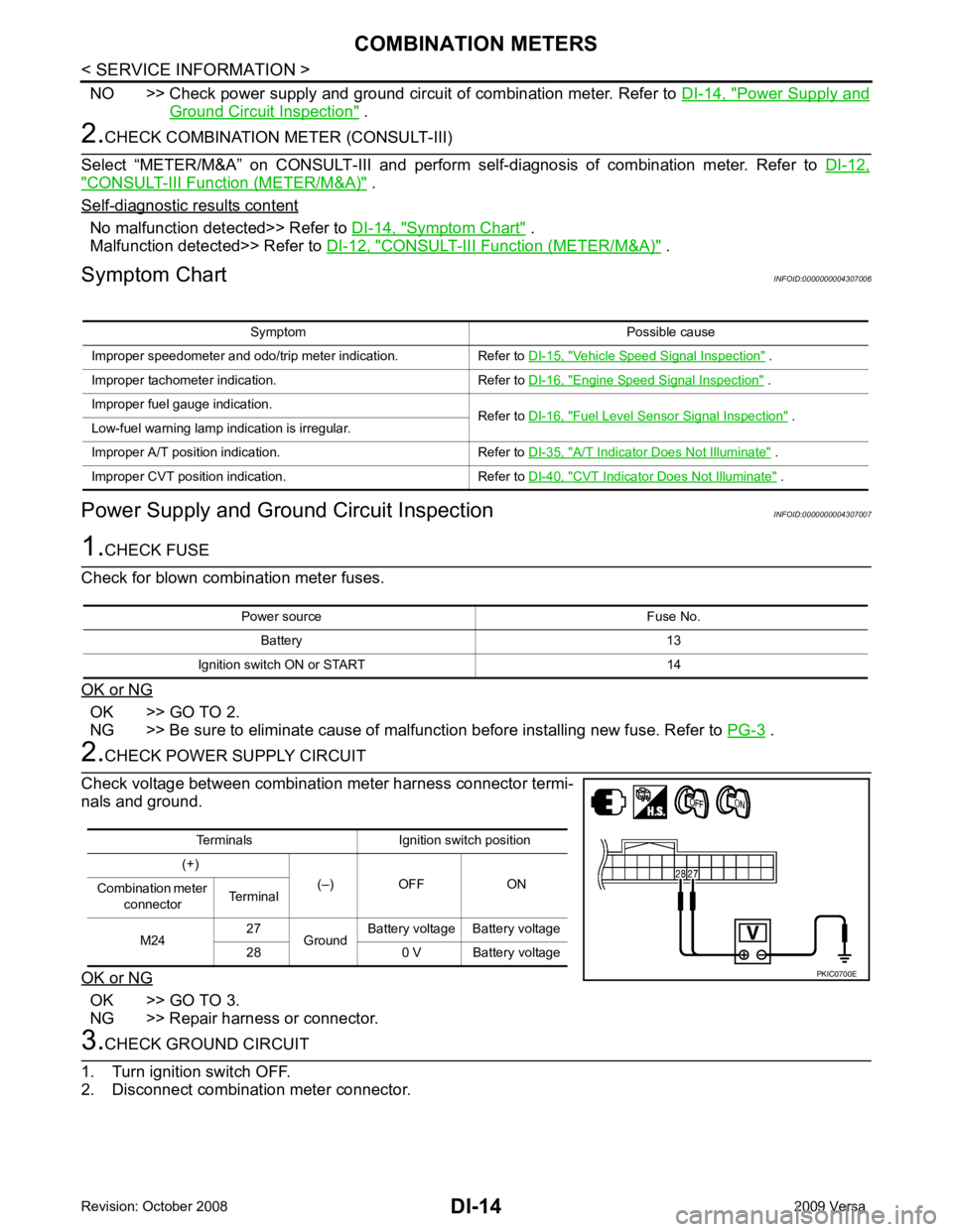
Ignition switch ON or START 14 Terminals Ignition switch position
(+) (–) OFF ON
Combination meter
connector Terminal
M24 27
Ground Battery voltage Battery voltage
28 0 V Battery voltage
Page 1317 of 4331
DI
N
O P
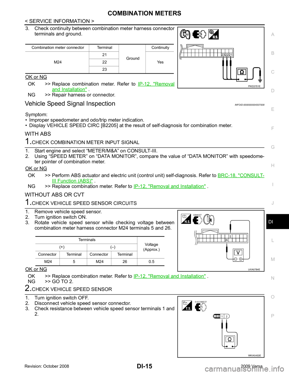
3. Check continuity between combination meter harness connector
terminals and ground.
OK or NG OK >> Replace combination meter. Refer to
IP-12, " Removal
and Installation " .
NG >> Repair harness or connector.
Vehicle Speed Signal Inspection INFOID:0000000004307008
Symptom:
• Improper speedometer and odo/trip meter indication.
• Display VEHICLE SPEED CIRC [B2205] at the result of self-diagnosis for combination meter.
WITH ABS OK >> Perform ABS actuator and electric uni
t (control unit) self-diagnosis. Refer to BRC-18, " CONSULT-
III Function (ABS) " .
NG >> Replace combination meter. Refer to IP-12, " Removal and Installation " .
WITHOUT ABS OR CVT OK >> Replace combination meter. Refer to
IP-12, " Removal and Installation " .
NG >> GO TO 2. WKIA5453E
Page 1318 of 4331
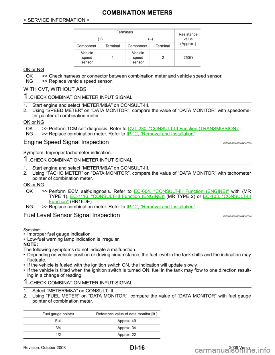
OK >> Check harness or connector between combination meter and vehicle speed sensor.
NG >> Replace vehicle speed sensor.
WITH CVT, WITHOUT ABS OK >> Perform TCM self-diagnosis. Refer to
CVT-230, " CONSULT-III Function (TRANSMISSION) " .
NG >> Replace combination meter. Refer to IP-12, " Removal and Installation " .
Engine Speed Signal Inspection INFOID:0000000004307009
Symptom: Improper tachometer indication. OK >> Perform ECM self-diagnosis. Refer to
EC-604, " CONSULT-III Function (ENGINE) " with (MR
TYPE 1), EC-1116, " CONSULT-III Function (ENGINE) " (MR TYPE 2) or
EC-103, " CONSULT-III
Function " (HR16DE).
NG >> Replace combination meter. Refer to IP-12, " Removal and Installation " .
Fuel Level Sensor Signal Inspection INFOID:0000000004307010
Symptom:
• Improper fuel gauge indication.
• Low-fuel warning lamp indication is irregular.
NOTE:
The following symptoms do not indicate a malfunction.
• Depending on vehicle position or driving circumstance, the fuel level in the tank shifts and the indication may
fluctuate.
• If the vehicle is fueled with the ignition switch ON, the indication will update slowly.
• If the vehicle is tilted when the ignition switch is turned ON, fuel in the tank may flow to one direction result-
ing in a change of reading.
Page 1319 of 4331
DI
N
O P
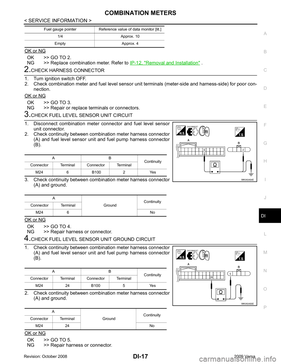
OK or NG OK >> GO TO 2.
NG >> Replace combination meter. Refer to IP-12, " Removal and Installation " .
OK >> GO TO 3.
NG >> Repair or replace terminals or connectors. OK >> GO TO 4.
NG >> Repair harness or connector. OK >> GO TO 5.
NG >> Repair harness or connector. 1/4 Approx. 10
Empty Approx. 4
Fuel gauge pointer Reference value of data monitor [lit.] A B
Continuity
Connector Terminal Connector Terminal
M24 6 B100 2 Yes
A GroundContinuity
Connector Terminal
M24 6 No
Page 1320 of 4331
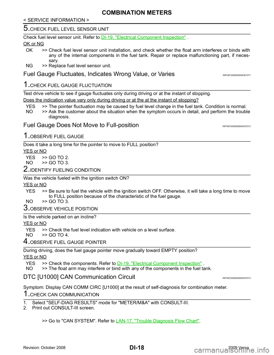
Electrical Component Inspection " .
OK or NG OK >> Check fuel level sensor unit installation, and c
heck whether the float arm interferes or binds with
any of the internal components in the fuel tank. Repair or replace malfunctioning part, if neces-
sary.
NG >> Replace fuel level sensor unit.
Fuel Gauge Fluctuat es, Indicates Wrong Value, or Varies INFOID:0000000004307011YES >> The pointer fluctuation may be caused by fuel
level change in the fuel tank. Condition is normal.
NO >> Ask the customer about the situation when the symptom occurs in detail, and perform the trouble
diagnosis.
Fuel Gauge Does Not Mo ve to Full-position INFOID:0000000004307012YES >> GO TO 2.
NO >> GO TO 3. YES >> Be sure to fuel the vehicle with the ignition switch OFF. Otherwise, it will take a long time to move
to FULL position because of the c haracteristic of the fuel gauge.
NO >> GO TO 3. YES >> Check the fuel level indication with vehicle on a level surface.
NO >> GO TO 4. YES >> Check the components. Refer to
DI-19, " Electrical Component Inspection " .
NO >> The float arm may interfere or bind with any of the components in the fuel tank.
DTC [U1000] CAN Communication Circuit INFOID:0000000004307013
Symptom: Display CAN COMM CIRC [U1000] at the re sult of self-diagnosis for combination meter. Trouble Diagnosis Flow Chart " .